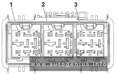
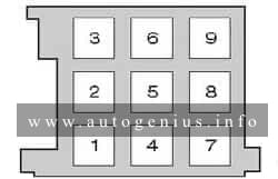
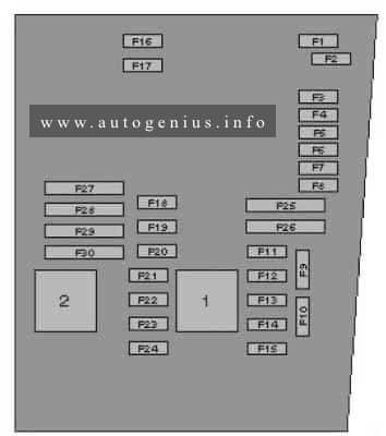
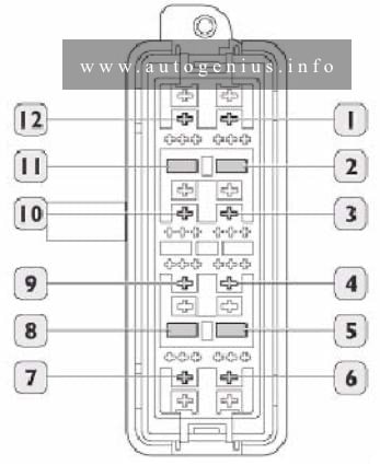
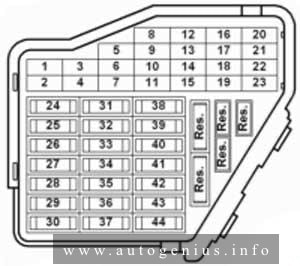
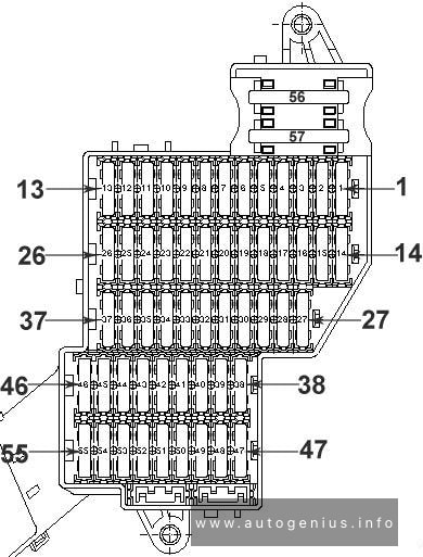
| № |
A |
Function/component |
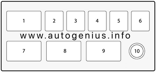
| 1 |
10 |
J99 – Heated exterior mirror relay*1
J131 – Heated driver seat control unit (T6/5)
J132 – Heated front passenger seat control unit (T6b/5)
W6 – Glove compartment light
Z20/ Z21 – Left/right washer jet heater element |
| 2 |
10 |
J1 – Turn signal relay (T7/6)
M5/ M7 – Front left/right turn signal bulb
M6/ M8 – Rear left/right turn signal bulb |
| 3 |
5 |
E1 – Lighting switch
E20 – Switches and instruments illumination regulator
J5 – Fog light relay (4/86) |
| 4 |
5 |
X – number plate light |
| 5 |
7,5 |
E45 – Cruise control system switch*2
E159 – Fresh air/air recirculation flap switch (T8b/5)
E184 – Fresh air and air recirculation switch*1
E227 – Cruise control system (CCS) SET button (T4q/3), CCS only*1
E231 – Exterior mirror heater button
F36 – Clutch pedal switch (T4q/3)
F47 – Brake pedal switch
G65 – High-pressure sender (T3e/3)
J89 – Daytime running lights change-over relay (8/86)
J255 – Climatronic control unit (T16c/9)*1
J293 – Radiator fan control unit (T14/9)
J386 – Driver door control unit (T18d/3)
T16 – 16-pin connector, self-diagnosis (T16/1T16/16)
V48 – Left headlight range control motor*1
V49 – Right headlight range control motor*1
Y2 – Digital clock*2
Y7 -Automatic anti-dazzle interior mirror*2 |
| 6 |
5 |
J393 – Convenience system central control unit (T23/5)
Vacant, model year 2004 |
| 7 |
10 |
F4 – Reversing light switch
F125 – Multifunction switch (T10t/10)*2
G22 – Speedometer sender
J226 – Starter inhibitor and reversing light relay (T9/5)
K142 – Selector lever position P/N warning lamp
M16 / M17 – Left/right reversing light bulb
T16 – 16-pin connector, self-diagnosis (T16/1) |
| 8 |
– |
Vacant
J412 – Mobile telephone operating electronics control unit (T18d/10)*3 |
| 9 |
5 |
E256 – TCS and ESP button (T6/6)
J104 – ABS control unit (T47a/4)
G85 – Steering angle sender (T6k/5) |
| 10 |
10 |
J285 – Control unit in dash panel insert (T32/30)
J393 – Convenience system central control unit (T23/17), models with window regulator from 2003 only
R – Radio
Y2 – Digital clock |
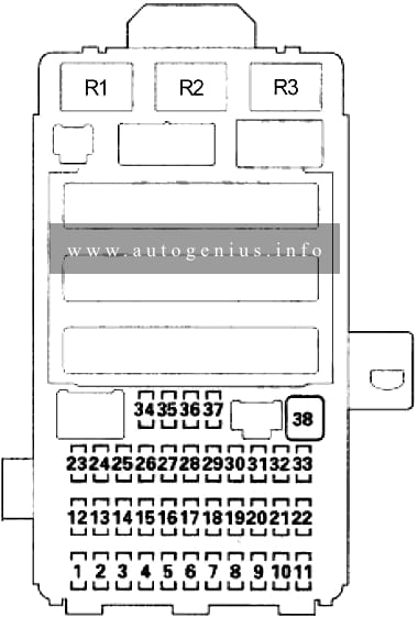
| 11 |
5 |
J285 – Control unit in dash panel insert (T32/1)
N110 – Selector lever lock solenoid |
| 12 |
7,5 |
T16 – 16-pin connector, self-diagnosis (T16/16)
J502 – Tyre pressure monitor control unit (T20b/3)*2 |
| 13 |
10 |
F – Brake light switch |
| 14 |
10 |
J220 – Motronic control unit (T121/62)
J271 – Motronic current supply relay
J393 – Convenience system central control unit (T23/22), models with window regulator from model year 2003 |
| 15 |
5 |
G85 – Steering angle sender (T6p/4) for TCS/ESP
J217 – Automatic gearbox control unit (T68/45)
J285 – Control unit in dash panel insert (T32/23)
Y2 – Digital clock*2 |
| 16 |
10 |
J293 – Radiator fan control unit (T14/4) |
| 17 |
– |
Vacant |
| 18 |
10 |
J5 – Fog light relay
J285 – Control unit in dash panel insert (T32/a17)
J607 – Right dip and main beam switch relay (for gas discharge bulb)*1
M32 – Right main beam bulb |
| 19 |
10 |
J606 – Left dip and main beam switch relay (for gas discharge bulb)*1
M30 – Left main beam bulb |
| 20 |
15 |
J607 – Right dip and main beam switch relay (for gas discharge bulb)*1
M31 – Right headlight dipped beam bulb |
| 21 |
15 |
J606 – Left dip and main beam switch relay (for gas discharge bulb)*1
M29 – Left headlight dipped beam bulb |
| 22 |
5 |
J285 – Control unit in dash panel insert (T32/26)
M3 – Right side light bulb*2
M22 – Right brake and tail light bulb
M34 – Front right side marker bulb*2
M36 – Front right turn signal and side marker bulb
M38 – Rear right side marker bulb |
| 23 |
5 |
J285 – Control unit in dash panel insert (T32/27)
M1 – Left side light bulb*2
M21 – Left brake and tail light bulb
M33 – Front left side marker bulb*2
M35 – Front left turn signal and side marker bulb
M37 – Rear left side marker bulb |
| 24 |
20 |
E22 – Intermittent wiper switch (T8c/8)
J31 – Automatic intermittent wash and wipe relay (T18a/13), for headlight washer system only |
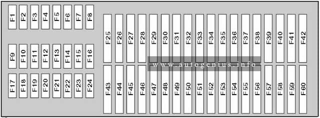
| 25 |
25 |
E9 – Fresh air blower switch (T6d/2)
J255 – Climatronic control unit (T16b/14)*1
V2 – Fresh air blower, for Climatronic only*1 |
| 26 |
25 |
E15 – Heated rear window switch (T6b/5)
Z1 – Heated rear window |
| 27 |
15 |
U1 – Cigarette lighter, from model year 2007
J29 – Blocking diode, from model year 2007
U18 – 12 V socket -2-
U19 – 12 V socket 3, in luggage compartment |
| 28 |
15 |
G6 – Fuel system pressurisation pump
J17 – Fuel pump relay (T9b/1)*3 |
| 29 |
15 |
J220 – Motronic control unit (T121/3)
J248 – Diesel direct injection system control unit (T121/37)*1
N30/ N31/ N32/ N33/ N83 – Injector, cylinder*2
J623 – Engine control unit (T80/4), engine code CBPA only*2
G70 – Air mass meter, (T5d/2), engine code BEW only, from June 2003 up to December 2006
J248 – Diesel direct injection system control unit, (T94/18), engine code BEW only, from June 2003 up to December 2006 |
| 30 |
20 |
J245 – Sliding sunroof adjustment control unit (T6l/4) |
| 31 |
20 |
F125 – Multifunction switch (T8a/7)*1
J217 – Automatic gearbox control unit (T68/23)
J539 – Brake servo control unit (T6k/3) |
| 32 |
30 |
N30/ N31/ N32/ N33 – Injector, cylinders, engine code CBPA only
N280 – Air conditioning system compressor regulating valve*2 |
| 32 |
15 |
J248 – Diesel direct injection system control unit (T121/2)
N146 – Metering adjuster*1 |
| 33 |
20 |
Vacant |
| 34 |
10 |
G40 – Hall sender, engine code BEW only, from June 2003 up to December 2006
J52 – Glow plug relay (engine codes ALH and BEW only)
J299 – Secondary air pump relay (T13/9)*3
J370 – Glow plug activation control unit, (6/87), engine code BEW only, from June 2003 up to December 2006
N18 – Exhaust gas recirculation valve (engine codes ALH and BEW only)
N75 – Charge pressure control solenoid valve
N79 – Heater element for crankcase breather*3
N108 – Commencement of injection valve (engine codes ALH and BEW only)
N239 – Variable intake manifold flap change-over valve (engine codes ALH and BEW only)
N205 – Inlet camshaft control valve 1 (engine codes ALH and BEW only)
N249 – Turbocharger air recirculation valve (engine codes ALH and BEW only)
N345 – Exhaust gas recirculation cooler change-over valve, engine code BEW only, from June 2003 up to December 2006
S130 – Secondary air pump fuse*3
V157 – Intake manifold flap motor, engine code BEW only, from June 2003 up to December 2006 |
| 35 |
30 |
U19 – 12 V socket 3, in luggage compartment
U10 – Trailer socket (T13/9)*3 |
| 36 |
15 |
E7 – Fog light switch (T17/2) |
| 37 |
20 |
J220 – Motronic control unit (T121/62)
J248 – Diesel direct injection system control unit (T121/88), engine codes ALH and BEW
J271 – Motronic current supply relay (1/30)
J393 – Convenience system central control unit (T23/17), models with window regulator
J623 – Engine control unit (T80/15), engine code CBPA only
S283 – Brake vacuum pump fuse |
| 38 |
15 |
E204 – Tank filler flap remote release switch
E233 – Rear lid remote release button
J386 – Driver door control unit (T29/19), models with window regulator
J387 – Front passenger door control unit (T29a/19), models with window regulator
J393 – Convenience system central control unit (T23/22)*3 |
| 39 |
15 |
E3 – Hazard warning light switch (T8d/8) |
| 40 |
20 |
H1 – Horn or dual tone horn
J4 – Dual tone horn relay (3/30) |
| 41 |
15 |
U1 – Cigarette lighter
U5 – 12 V socket
U18 – 12 V socket -2-, from 07.03
U19 – 12 V socket 3, in luggage compartment, from 07.03
Vacant*3 |
| 42 |
25 |
R – Radio (T8/5, T8/7) |
| 43 |
10 |
G39 – Lambda probe
G70/G42 – Air mass meter/ Intake air temperature sender, engine codes BPS, BPR only
G108 – Lambda probe 2
G130 – Lambda probe after catalytic converter
G465 – Centre Lambda probe for bank 1 catalytic converter, engine code BPR only
J299 – Secondary air pump relay (4/85)*1
N80 – Activated charcoal filter system solenoid valve 1
N112-Secondary air inlet valve*1
V144 – Fuel system diagnostic pump |
| 43 |
10 |
F36 – Clutch pedal switch
F47-Brake pedal switch
J359 – Low heat output relay
J360 – High heat output relay
N79-Heater element for crankcase breather |
| 44 |
15 |
J131 – Heated driver seat control unit (T6/4)
J132 – Heated front passenger seat control unit (T6b/4) |
1 – model year 2002 up to july 2005
2 – from model July 2005
3 – from model July 2009 |