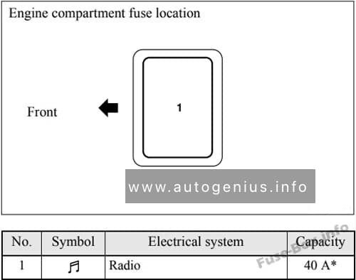
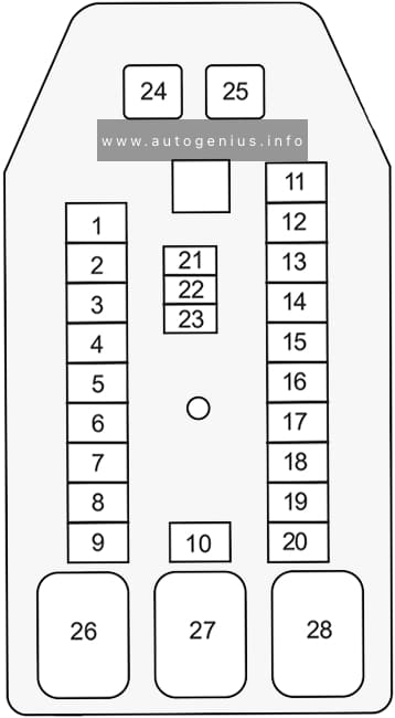
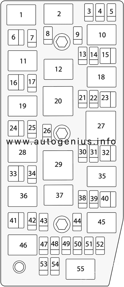
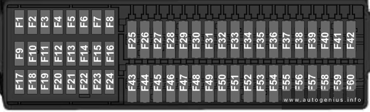
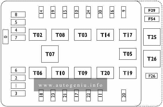
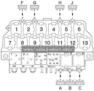
Mitsubishi Galant (2004 – 2012) – fuse box diagram

Mitsubishi Galant (2004 – 2012) – fuse box diagram

Year of production: 2004, 2005, 2006, 2007, 2008, 2009, 2010, 2011, 2012

Passenger Compartment Fuse Box

Fuse Box Location

The fuse box is located on the driver’s the side of the instrument panel,  behind the cover.

Mitsubishi Galant (2004 - 2012)- fuse box location - passenger compartment
Mitsubishi Galant (2004 – 2012)- fuse box location – passenger compartment

Fuse Box Diagram

Mitsubishi Galant (2004 - 2012)- fuse box location - passenger compartment
Mitsubishi Galant (2004 – 2012)- fuse box location – passenger compartment
Amps Function
1
2
3 30A Radio
4 20A Sunroof
5 30A Rear window defogger
6 30A Heater
7
8
9 15A Power outlet
10 15A Power door locks
11
12
13 7,5A Engine control
14 7,5 Outside rearview mirrors
15
16 15A Cigarette lighter
17 7,5A Engine control
18
19 7,5A Door mirror heater
20 7,5 Relay
21
22 7,5A Back-up light
23 7,5A Gauge
24 10A Ignition coil
25 20A Spare fuse
26 30A Spare fuse
27 30A Spare fuse

Engine Compartment Fuse Box

Fuse Box Location

The fuse boxes are located in the engine compartment (left-side).

Mitsubishi Galant (2004 - 2012)- fuse box location - engine compartment
Mitsubishi Galant (2004 – 2012)- fuse box location – engine compartment
Type A
Mitsubishi Galant (2004 - 2012)- fuse box location - engine compartment (type A)
Mitsubishi Galant (2004 – 2012)- fuse box location – engine compartment (type A)
Type B
Mitsubishi Galant (2004 - 2012)- fuse box location - engine compartment (type B)
Mitsubishi Galant (2004 – 2012)- fuse box location – engine compartment (type B)
Type C
Mitsubishi Galant (2004 - 2012)- fuse box location - engine compartment (type C)
Mitsubishi Galant (2004 – 2012)- fuse box location – engine compartment (type C)

Fuse Box Diagram

Type A
Mitsubishi Galant (2004 - 2012)- fuse box diagram - engine compartment (type A)
Mitsubishi Galant (2004 – 2012)- fuse box diagram – engine compartment (type A)
Assignment of the fuses in the Engine compartment
Amps Function
1 80A* Battery
2 30A* Radiator fan motor
3 60A* Anti-lock braking system
4 40A* Ignition switch
5 30A* Power window control
6 15A Front fog lights/Daytime running lights
7 20A Heated seat
8 15A Horn
9 20A Engine control
10 10A Air conditioning
11 15A Stop lights
12 10A Rear fog light
13 7,5A Alternator
14 10A Hazard warning flasher
15 20A Automatic transaxle
16 10A Headlight high beam (right)
17 10A Headlight high beam (left)
18 10A Headlight low beam (right)
19 10A Headlight low beam (left)
20 7,5A Taił light (right)
21 7,5 Taił light (left)
22 10A Dome light
23 10A Radio
24 15A Fuel pump
25 30A Windshield wiper
*: Fusible link
Type B
Mitsubishi Galant (2004 - 2012)- fuse box diagram - engine compartment (type B)
Mitsubishi Galant (2004 – 2012)- fuse box diagram – engine compartment (type B)
Amps Function
1 20A* Condenser fan motor
*: Fusible link
Type C
Mitsubishi Galant (2004 - 2012)- fuse box diagram - engine compartment (type C)
Mitsubishi Galant (2004 – 2012)- fuse box diagram – engine compartment (type C)
Amps Function
1 40A* Radio
*: Fusible link

Cigar lighter (power outlet) fuses in the Mitsubishi Galant are the fuses #9 (Power outlet), and #16 (Cigarette lighter) in the Passenger compartment fuse box.

WARNING: Terminal and harness assignments for individual connectors will vary depending on vehicle equipment level, model, and market.

Holden Colorado (RC; 2009 – 2012) – fuse and relay box diagram

Holden Colorado (RC; 2009 – 2012) – fuse and relay box diagram


Year of production: 2009, 2010, 2011, 2012


This article provides the first-generation Holden Colorado (RC), manufactured between 2008 and 2012. It provides fuse box diagrams for the 2009, 2010, 2011, and 2012 models, along with details on the location of the fuse panels inside the vehicle. Additionally, it explains the function of each fuse (fuse layout) and relay.


Passenger Compartment Fuse Box

Fuse Box Location

The fuse panel is located on the right-hand side of the dashboard.  To open the fuse cover, open the driver’s door, pull the top of the cover out, then pivot downward.

Holden Colorado (RC; 2009 - 2012)- fuse box location - passenger compartment
Holden Colorado (RC; 2009 – 2012)- fuse and relay box location – passenger compartment


Fuse Box Diagram

Holden Colorado (RC; 2009 - 2012)- fuse and relay box diagram - passenger compartment
Holden Colorado (RC; 2009 – 2012)- fuse and relay box diagram – passenger compartment


Assignment of the fuses in the passenger compartment

Amps Description
1 10A Meter
2
3 10A/15A Petrol L4: IG coil
HFV6: Engine
Diesel: TCM
4 15A Back light
5 10A Turn light
6 10A Elec. IG
7 10A Petrol L4: Engine
HFV6: ECU
Diesel: Engine
8 10A ABS / 4WD
9 20A Frt wiper
10 10A SRS
11 10A Audio
12 20A Cigar & Acc socket
13 15A Audio (+B)
14 20A Door lock
15 10A Meter (+B)
16 10A Room light
17
18 15A Stop light
19
20 10A Starter
21 10A Spare
22 15A Spare
23 20A Spare
24 20A HFV6, Diesel: RR defog (Slow blow fuse)
25 30A HFV6, Diesel: Power window (Slow blow fuse)
26 HFV6, Diesel: RR defog relay
27 HFV6, Diesel: Power window relay
28


Engine Compartment Fuse Box

Fuse Box Location

This fuse box is located on the passenger side of the engine compartment. It contains circuit fuses, main fuses and relays.  To remove the cover, press the catch on the side of the fuse box toward the engine and release the two tabs at the opposite side.

Holden Colorado (RC; 2009 - 2012)- fuse box location - engine compartment
Holden Colorado (RC; 2009 – 2012)- fuse box location – engine compartment


Fuse Box Diagram

Holden Colorado (RC; 2009 - 2012)- fuse and relay box diagram - engine compartment
Holden Colorado (RC; 2009 – 2012)- fuse and relay box diagram – engine compartment


Assignment of the fuses in the engine compartment

Amps Description
1 10A/15A Petrol L4: ECM (15A)
HFV6: ECM (15A)
Diesel: ACG (S) (10A)
2 10A/15A HFV6: O2 Sensor pre (15A)
Diesel: ECM (B) (10A)
3 10A/20A Petrol L4: Trailer (20A)
HFV6: ECM (B) (10A)
Diesel: Fuel pump (10A)
4 10A Petrol L4: ACG (S)
HFV6: TCM/PIM (B)
Diesel: Engine
5 10A H/light-high (RH)
6 10A H/light-high (LH)
7 10A H/light-low (RH)
8 10A H/light-low (LH)
9 20A Petrol L4: Fuel pump
HFV6: Trailer
Diesel: Trailer
10 10A/20A Petrol L4: O2 Sensor (10A)
Diesel: Cond. Fan (20A)
11 10A Tail light (RH)
12 10A Illumi & tail light (LH)
13 10A A/C
14 10A HFV6: 4WD
Diesel: 4WD
15 10A Horn
16 10A Hazard
17 15A HFV6: O2 Sensor post
18 15A HFV6: IGN. coil (RH)
19 15A HFV6: IGN. coil (LH)
Slow blow fuses
20 100A/120A Petrol L4: Main (100A)
Diesel: Main (120A)
21 20A/40A HFV6: Frt fog light (20A)
Diesel: ABS-1 (40A)
22 20A/60A HFV6: Rad. Fan (60A)
Diesel: ABS-2 (20A)
23 20A/40A Petrol L4: Cond. Fan (20A)
HFV6: Fuel pump (20A)
Diesel: ECM (40A)
24 40A IG-1
25 30A HFV6: Blower
Diesel: Blower
26 20A/40A Petrol L4: Frt fog light (20A)
HFV6: ABS-1 (40A)
Diesel: Frt fog light (20A)
27 20A/30A/60A Petrol L4: Blower (30A)
HFV6: ABS-2 (20A)
Diesel: Glow (60A)
28 50A/60A Petrol L4: IG-2 (50A)
HFV6: IG-2 (60A)
Diesel: IG-2 (60A)
Relays:
X-1 Petrol L4: Tail light
HFV6: Fog light
Diesel: Fog light
X-2 Petrol L4: Fuel pump
HFV6: Tail light
Diesel: Tail light
X-3 Horn
X-4 H/light dimmer
X-5 Diesel: Glow
X-6 Petrol L4: Starter
HFV6: Headlight
Diesel: Headlight
X-7 Petrol L4: Headlight
Diesel: Starter cut
X-8 Diesel: Starter
X-9 Petrol L4: Frt fog light
Diesel: Cond. fan
X-10 Petrol L4: Cond. fan
Diesel: Transmission
X-11 Heater
X-12 HFV6: ECM main
Diesel: ECM main
X-13 Petrol L4: Starter cut
HFV6: Fuel pump
Diesel: Fuel pump
X-14 A/C comp.
X-15 Petrol L4: A/C thermo
HFV6: Starter
Diesel: A/C thermo
46
47 Horn
48 Radiator fan
49 Fuel pump
50 Headlamp levelling / Adaptive forward lighting
51
52
53 Transmission control module / Engine control module
54 Vacuum pump / lnstrument panel cluster / Heating ventilation / Air conditioning system

WARNING: Terminal and harness assignments for individual connectors will vary depending on vehicle equipment level, model, and market.

Holden  Captiva 7 (2006 – 2010) – fuse and relay box diagram

Holden  Captiva 7 (2006 – 2010) – fuse and relay box diagram

Year of production: 2006, 2007, 2008, 2009, 2010


The Holden Captiva / Captiva 7 (CG, pre-facelift) is a compact crossover SUV that was manufactured between 2006 and 2011. This article provides fuse box diagrams for the 2006, 2007, 2008, 2009, and 2010 models of the Holden Captiva. It also includes details about the location of the fuse panels within the vehicle and outlines the function and layout of each fuse and relay.


Passenger Compartment Fuse Box

Fuse Box Location

The fuses are located on the left-hand side of the driver’s side footwell. To open the fuse cover, pull the top of the cover outward.

Holden Captiva 7 - fuse box location - passenger compartment
Holden Captiva 7 – fuse and relay box location – passenger compartment


Fuse Box Diagram

Holden Captiva 7 - fuse box diagram - passenger compartment
Holden Captiva 7 – fuse and relay box diagram – passenger compartment


Assignment of the fuses in the passenger compartment

Amps Allocation
1 10A Front mirror
2 20A Door lock
3 Spare
4 15A Front door lock
5 15A BCM (VB6)
6 20A APO 1 (Additional power outlet 1)
7 20A Cigar lighter
8 20A APO 2 (Additional power outlet 2)
9 15A BCM (VB3)
10 20A Heat/mat
11 20A Passenger power window
12 15A TCM
13 15A Audio
14 20A Driver’s power window
15 15A Engine
16 15A BCM (VB4)
17 10A XBCM
18 15A BCM (VB5)
19 10A 2006-2007: Trailer
20 10A 2006-2007: RR CLS
21 10A 2006-2007: PKLP-RH
22 Relay ACC/RAP
23 10A Lift glass
24 15A Air conditioning
25 10A Air conditioning
26 Relay run/crank
27 15A OSRVM HT
28 20A BCM (VB2)
29 10A 2006-2007: SSPS
30 15A BCM (VB7)
31 10A Clock
32 10A Instrument cluster
33 2A Ignition switch
34 10A BCM (VB1)
35 10A Ignition 1
36 10A Rear defrost
37 10A 2006-2007: CTD Horn
38 10A Airbag
39 10A Airbag
40 2A 2006-2007: WHL S/W
41 10A Front washer


Engine Compartment Fuse Box

Fuse Box Location

This fuse box is located on the passenger side of the engine compartment, it contains circuit fuses, main fuses and relays. To remove the cover, press the catch on the side of the fuse box toward the engine and release the two tabs at the opposite side.

Holden Captiva 7 - fuse box location - engine compartment
Holden Captiva 7 – fuse and relay box location – engine compartment


Fuse Box Diagram

Holden Captiva 7 - fuse box diagram - engine compartment
Holden Captiva 7 – fuse and relay box diagram – engine compartment


Assignment of the fuses in the engine compartment

Amps Allocation
1 Starter relay
2 Main relay
3 20A ECM
4 15A Engine 2
5 15A Engine 1
6 20A Starter
7 10A Main
8 10A A/C compressor
9 15A Engine 3
10 Auxiliary fan relay
11 A/C compressor relay
12 Main fan relay
13 15A AWD
14 15A Fuel
15 30A Main fan
16 40A ABS
17 20A ABS
18 Fuel relay
19 Horn relay
20 Fan control relay
21 Spare
22 15A Stop
23 30A Auxiliary fan
24 40A Run
25 25A Wiper
26 15A Horn
27 Wiper speed relay
28 Wiper relay
29 Run relay
30 15A Anti theft
31 20A Sunroof
32 40A Accessory / lgnition
33 60A Battery
34 30A Power seat
35 Defog relay
36 Front fog relay
37 Park lamp relay
38 15A H/light low RH
39 15A H/light low LH
40 30A Defog
41 20A Rear wiper
42 15A H/light high
43 15A Front fog
44 10A Park lamp LH
45 H/light low relay
46 H/light high relay
47 Spare
48 Spare
49 10A Park lamp RH
50 15A TCM
51 20A H/light washer
52 Spare
53 Spare
54 Spare
55 H/light washer relay
R1 DRIVING LAMPS
R2 HEADLAMP WASHER
R3 REAR WASHER PUMP
R4 FRONT WASHER PUMP
R5 REAR DEMISTER
R6 FRONT WIPER CONTROL
R7 WIPER SPEED
R8 ENGINE CONTROL MODULE
R9
R10 INCLR PUMP
R11
R12 REAR WIPER CONTROL
R13 FOG LAMPS
R14 LOW BEAM HEADLAMPS
R15 HIGH BEAM HEADLAMPS
R16 STARTER
R17 RUN / CRANK
R18 BRAKE VACUUM PUMP
R19 AIR-CONDITIONING CONTROL
R20 HORN


Diesel Auxiliary Fuse Box

Fuse Box Location

Holden Captiva 7 - fuse box location - diesel auxiliary fuse box compartment
Holden Captiva 7 – fuse and relay box location – diesel auxiliary fuse box compartment


Fuse Box Diagram

Holden Captiva 7 - fuse box location - diesel auxiliary fuse box compartment
Holden Captiva 7 – fuse and relay box location – diesel auxiliary fuse box compartment


Assignment of the fuses in the auxiliary fuse box

Amps Allocation
1 Relay PTC 3
2 40A PTC 3
3 40A PTC 2
4 40A PTC 1
5 30A F/F HTR
6 60A GPCU
7 Relay PTC 2
8 Relay PTC 1
9 Relay F/F HTR
10 B+


WARNING: Terminal and harness assignments for individual connectors will vary depending on vehicle equipment level, model, and market.

Acura  CSX (2005 – 2011) – fuse and relay box diagram

Acura  CSX (2005 – 2011) – fuse and relay box diagram


Year of production: 2005, 2006, 2007, 2008, 2009, 2010, 2011


This article covers the second-generation  Acura CSX, produced from 2005 to 2011. It includes fuse box diagrams for the 2005, 2006, 2007, 2008, 2009, 2010 and 2011 models, provides details on the location of the fuse panels inside the vehicle, and explains the function and layout of each fuse.


Passenger Compartment

Fuse box location

The interior fuse box is on the driver’s lower left side.

Acura CSX (2005 - 2011)- fuse and relay box location - passenger compartment
Acura CSX (2005 – 2011)- fuse and relay box location – passenger compartment


Fuse box diagram

Acura CSX (2005 - 2011)- fuse and relay box diagram - passenger compartment
Acura CSX (2005 – 2011)- fuse and relay box diagram – passenger compartment


Assignment of the fuses in the passenger compartment

No.
A
Protected Component
1 7.5 Power Mirror Switch Light, Power Window Relay
2 15 Fuel Pump, ECM/PCM, Immobilizer-Keyless Control Unit
3 10 Alternator, CMP Sensor A, ECM/PCM, ELD, EVAP Canister Purge Valve, EVAP Canister Vent Shut Valve. MAF/IAT Sensor, Reverse Lock-Out (Type-S), HO2S (Secondary)
4 7.5 ABS Modulator-Control Unit (’06-’07), EPS Control Unit, VSA Modulator-control Unit (’08-’09), Yaw Rate-lateral Acceleration Sensor (’07-(Type-S) ’08-’09)
5 15 Seat Heater Relays, Seat Heaters
6 20 Fog Light Relay, Fog Lights
7 7.5 TPMS Control Unit
8  –
9 7.5 ODS Unit, Passenger’s Airbag CUTOFF Indicator, SRS Unit
10 7.5 Gauge Control Module (Tach), Back-up Light Switch (MAT), Shift Lock Solenoid (A/T), MICU, TPMS Control Unit (’08-’09)
11 10 SRS Unit
12 10 Right Headlight (High Beam)
13 10 Left Headlight (High Beam)
14 7.5 Audio Unit Light, Climate Control Unit Light, Dash Lights Brightness Controller and Odometer Select/Reset Switch Light, Driver’s Footwell Light, Glove Box Light, Hazard Warning Switch Light. Moonroof Switch Light, Navigation Unit, Passenger’s Airbag CUTOFF Indicator Light, Select/Reset Switch Light, Steering Wheel Switches Light, VSA OFF Switch Light
15 7.5 Parking Lights, Taillights, License Plate Lights, Side Marker Lights
16 10 Right Headlight (Low Beam)
15 Right HID Unit
17 10 Left Headlight (Low Beam)
15 Left HID Unit
18 20 Headlight High Main, Multiplex Integrated Control Unit (MICU)
19 15 Small (Main), Multiplex Integrated Control Unit (MICU)
20  –
21 20 HID: Headlight Low Main, Multiplex Integrated Control Unit (MICU)
30 without HID: Headlight Low Main, Multiplex Integrated Control Unit (MICU)
22 7.5 IG1 HAC
23 7.5 STS
24 20 Moonroof Control/Motor
25 20 Door Lock, Multiplex Integrated Control Unit (MICU)
26 20 Driver’s Power Window Motor
27 20 *Option
28 15 Console Accessory Power Socket
29 15 Front Accessory Power Socket
30 20 Front Passenger’s Power Window Motor
31  –
32 20 Right Rear Power Window Motor, Moonroof Switch, Moonroof Control Unit/Motor
33 20 Left Rear Power Window Motor
34  –
35 7.5 Audio Unit, Front Accessory Power Socket Relay, Console Accessory Power Socket Relay, Stereo Amplifier, HandsFreeLink Control Unit, Ignition Key Switch, Navigation Unit
36 10 Climate Control Unit, Power Mirrors, Recirculation Control Motor, A/C Compressor Clutch Relay, Blower Motor Relay, Power Mirror Defogger Relay, Rear Window Defogger Relay, Fan Control Relay and Radiator Fan Relay
37 7.5 Daytime Running Lights, Multiplex Integrated Control Unit (MICU)
38 30 Front Wiper, Multiplex Integrated Control Unit (MICU)
Relay
R1 Power Window
R2 Fuel Pump (PGM-FI Main 2)
R3 Starter Cut


Engine Compartment

Fuse box diagram

Acura CSX (2005 - 2011)- fuse and relay box diagram - engine compartment
Acura CSX (2005 – 2011)- fuse and relay box diagram – engine compartment


Assignment of the fuses in the engine compartment

o.
A
Protected Component
1 100 Battery, Power Distribution
70 EPS Control Unit
2 50 Ignition Switch
80 ’06-07: Fuses (Passenger Compartment): 5, 6, 7, 27, 28, 29, 31
60 ’08-’09: Fuses (Passenger Compartment): 5, 6, 7, 27, 28, 29, 31
3 30 ABS Modulator-Control Unit, VSA Modulator-Control Unit
30 ABS Modulator-control Unit
40 VSA Modulator-control Unit
4 50 Fuses (Passenger Compartment): 18, 19, 20, 21
40 Fuses (Passenger Compartment): 24, 25, 26, 30, 32, 33
5  –
6 20 A/C Condenser Fan Motor
7 20 Radiator Fan Motor
8 30 Rear Window Defogger
9 40 Blower Motor
10 10 Hazard Lights
11 15 A/F Sensor (Sensor 1), ECM/PCM
12 15 Brake Lights, ECM/PCM, Horn, Multiplex Integrated Control Unit (MICU)
13  –
14  –
15 7.5 A/C Condenser Fan Relay
16  –
17 15 Stereo Amplifier
18 15 ECM/PCM, Ignition Coils
19 15 CKP Sensor, CMP Sensor B, ECM/PCM, ETCS Control Relay, Injectors, PGM-FI Main Relay 1 (Fl MAIN), PGM-FI Main Relay 2 (Fuel Pump)
20 7.5 A/C Compressor Clutch
21 15 ECM/PCM (ETCS Control Relay)
22 7.5 Ceiling Lights. Courtesy Light, Mao Lights, Trunk Lights
23 10 Audio Unit, Data Link Connector, Gauge Control Module (Tach), Gauge Control Module (Speedo), Hazard Warning Switch, Immobilizer-Keyless Control Unit, Multiplex Integrated Control Unit (MICU), HandsFreeLink Control Unit, Navigation Unit
Relay
R1 Radiator Fan
R2 A/C Condenser Fan
R3 Fan Control
R4 Electronic Throttle Control System (ETCS) Control
R5 Blower Motor
R6 Power Mirror Defogger
R7 PGM-FI Main (No.1)
R8 Rear Window Defogger
R9 PGM-FI Sub
R10 A/C Compressor Clutch
R11 Ignition Coil


WARNING: Terminal and harness assignments for individual connectors will vary depending on vehicle equipment level, model, and market.

Volkswagen Jetta (V, Type 1K; 2005 – 2009) – fuse and relay box diagram

Volkswagen Jetta (V, Type 1K; 2005 – 2010) – fuse and relay box diagram

Year of production: 2005, 2006, 2007, 2008, 2009, 2010


The Volkswagen Jetta was a compact family car produced from 1992 to 1999. In this article, you will find fuse box diagrams for Volkswagen Jetta V, type 1K models from 2005 to 2010, along with details on the fuse panel locations inside the vehicle and the specific functions of each fuse (fuse layout) and relay.

Fuse box location

Volkswagen Jetta (V, Type 1K; 2005 - 2010)- fuse and relay box location
Volkswagen Jetta (V, Type 1K; 2005 – 2010)- fuse and relay box location


  1. Engine compartment fuse box
  2. Relay carrier on onboard supply control unit (left under dash panel)
  3. The instrument panel fuse panel
  4. Additional relay carrier, under box in engine compartment

Passenger compartment

Fuse box diagram

Volkswagen Jetta (V, Type 1K; 2005 - 2010)- fuse and relay box diagram - passenger compartment
Volkswagen Jetta (V, Type 1K; 2005 – 2010)- fuse and relay box diagram – passenger compartment


Assignment of the fuses and relays in the passenger compartment

No.
A
Function/component
1 10 T16 – Diagnostic connection (T16/1)
J623 – Engine control unit
J757 – Engine component current supply relay (167) (from May 2005)
J538 – Fuel pump control unit (from May 2005)
J485 – Relay for auxiliary heater operation (from 2006)
N79 – Heater element for crankcase breather (from 2006)
G70 – Air mass meter (from 2006)
J431 – Control unit for headlight range control (from 2006)
2 5 J104 – ABS control unit
E132 – Traction control system switch
E256 – TCS and ESP button
E492 – Tyre pressure monitor display button
F – Brake light switch (low; from November 2005)
10 J623 – Engine control unit (from 2006)
V49 – Right headlight range control motor (from 006)
V48 – Left headlight range control motor (from 2006)
E102 – Headlight range control regulator (from 2006)
J538 – Fuel pump control unit (from 2006)
J345 – Trailer detector control unit (from 2006)
J587 – Selector lever sensors control unit (from 2006)
J533 – Data bus diagnostic interface (from 2006)
J285 – Control unit in dash panel insert (from 2006)
J500 – Power steering control unit (from 2006)
J104 – ABS with EDL control unit (from 2006)
E132 – Traction control system switch (from 2006)
E256 – TCS and ESP button (from 2006)
G476 – Brake pedal position sender (from 2006)
E1 – Light switch (from 2006)
F47 – Brake pedal switch, (from November 2005)
3 10 J500 – Power steering control unit (up to May 2005)
5 J234 – Airbag control unit (from May 2005)
4 5 E16 – Heater/heat output switch
G65 – High-pressure sender
J131 – Heated driver seat control unit
J132 – Heated front passenger seat control unit
J255 – Climatronic control unit
K216 – Stabilisation program warning lamp 2 (from May 2005)
M17 – Reversing light bulb (from May 2005)
E422 – Tyre pressure monitor display button (from May 2005)
G266 – Oil level and oil temperature sender (high; from May 2005)
J530 – Garage door operation control unit (from May 2006)
G128 – Seat occupied sensor, front passenger side (from May 2006)
Y7 – Automatic anti-dazzle interior mirror (from May 2006)
Z20 – Left washer jet heater element (from May 2006)
Z21 – Right washer jet heater element (from May 2006)
10 G266 – Oil level and oil temperature sender (high; from November 2005)
M17 – Reversing light (high; from November 2005)
J255 – Climatronic control unit (high; from November 2005)
G65 – High-pressure sender (high; from November 2005)
E16 – Switch for heater and heater output (high; from November 2005)
J530 – Garage door operation control unit (high; from November 2005)
N253 – Battery isolation igniter (high; from November 2005)
Y7 – Automatic anti-dazzle interior mirror (high; from November 2005)
E422 – Tyre pressure monitor display button (high; from November 2005)
K216 – Stabilisation programme warning lamp 2 (high; from November 2005)
Z20 – Left washer jet heater element (high; from November 2005)
Z21 – Right washer jet heater element (high; from November 2005)
L71 – Illumination for traction control system switch (high; from November 2005)
J301 – Air conditioning system control unit (high; from May 2007)
5 5 F47 – Cruise control system brake pedal switch (to May 2005)
G476 – Clutch position sender
J431 – Control unit for headlight range control (from May 2005)
J500 – Power steering control unit (from May 2005)
J745 – Cornering light and headlight range control unit, on right headlight, (high; December 2006)
10 J745 – Cornering light and headlight range control unit, on right headlight (low; from May 2006), (high; from May 2007)
6 5 J285 – Control unit in dash panel insert (up to May 2006)
J538 – Fuel pump control unit (up to May 2006)
J533 – Data bus diagnostic interface (up to May 2006)
F125 – Multifunction switch (up to May 2006)
J587 – Selector lever sensors control unit (up to May 2006)
F189 – Tiptronic switch (up to May 2006)
J745 – Cornering light and headlight range control unit, on left of headlight (high; December 2006)
10 J745 – Cornering light and headlight range control unit, on left headlight (low; from May 2006), (high; from May 2007)
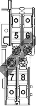
7 5 J431 – Control unit for headlight range control (to May 2005)
Y7 – Automatic anti-dazzle interior mirror (from May 2005)
Not assigned (from May 2006)
8 5 Y7 – Automatic anti-dazzle interior mirror (to May 2005)
10 J345 – Trailer detector control unit (from May 2005)
Not assigned (from May 2006)
9 5 Not assigned (to May 2005)
J503 – Control unit with display for radio and navigation system (only commercial navigation system unit) (from May 2005)
Not assigned (from May 2006)
10 5 J412 – Mobile telephone operating electronics control unit (to May 2005)
J530 – Garage door operation control unit (from May 2005)
J706 – Seat occupied recognition control unit (from May 2005)
Not assigned (from May 2006)
11 5 J345 – Trailer detector control unit (to May 2005)
Not assigned (from May 2005)
10 J745 – Cornering light and headlight range control unit, on right headlight, (from May 2007)
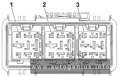
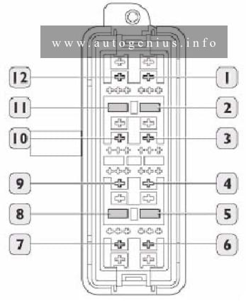
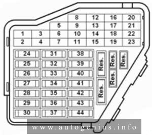
12 10 J386 – Driver door control unit
J387 – Front passenger door control unit
13 10 E1 – Light switch
T16 – Diagnostic connection (T16/16)
F47 – Brake pedal switch (from May 2005)
G397 – Sensor for rain and light detection (from 2006)
G197 – Magnetic field sender for compass (from 2006)
14 5 F – Brake light switch (low; from May 2005)
J217 – Automatic gearbox control unit
10 J587 – Selector lever sensors control unit (from 2006)
R149 – Remote control receiver for auxiliary coolant heater (from 2006)
J301 – Air conditioning system control unit (from 2006)
J255 – Climatronic control unit (from 2006)
E16 – Heater/heat output switch (from 2006)
J446 – Parking aid control unit (from 2006)
J104 – ABS with EDL control unit (from 2006)
E94 – Heated driver seat regulator (from 2006)
E95 – Heated front passenger seat regulator (from May 2006)
J217 – Automatic gearbox control unit (from November 2005)
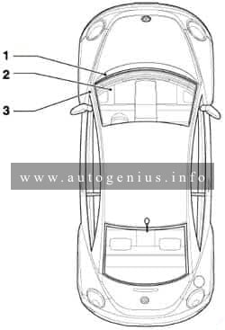
15 7.5 J519 – Onboard supply control unit (interior illumination)
16 10 E16 – Heater/heat output switch
J301 – Air conditioning system control unit
J255 – Climatronic control unit
R149 – Remote control receiver for auxiliary coolant heater
Not assigned (from May 2006)
5 J515 – Aerial selection control unit (high; from November 2005)
17 5 G397 – Rain and light detector sensor (up to May 2006)
J515 – Aerial selection control unit (up to May 2006)
G273 – Interior monitoring sensor (from 2006)
G384 – Vehicle inclination sender (from 2006)
H12 – Alarm horn (from 2006)
18 5 J446 – Parking aid control unit
J587 – Selector lever sensors control unit
Not assigned (from 2006)
19 5 J754 – Accident data memory
20 5 J104 – ABS with EDL control unit
Not assigned (from 2006)
21 5 J503 – Control unit with display for radio and navigation system (only commercial navigation system unit) (up to May 2005)
Not assigned (from May 2005)
J542 – Control unit for engine speed governor, in front left footwell (special vehicles) (high; from May 2007)
J378 – PDA control unit (special vehicles) (from May 2007)
22 40 V2 – Fresh air blower (Climatronic)
N253 – Battery isolation igniter (rear battery) (high; from May 2005)
23 30 J386 – Driver door control unit (window regulator)
J387 – Front passenger door control unit (window regulator)
24 25 U1 – Cigarette lighter (up to May 2006)
U9 – Rear cigarette lighter (up to May 2006)
U5 – 12 V socket (criminal investigation department)
20 J388 – Rear left door control unit (central locking) (from 2006)
J389 – Rear right door control unit (central locking) (from 2006)
J393 – Convenience system central control unit (from 2006)
25 J388 – Rear left door control unit (central locking) (high; from May 2007)
J389 – Rear right door control unit (central locking) (high; from May 2007)
J393 – Convenience system central control unit (high; from May 2007)
25 25 Z1 – Heated rear window
J301 – Air conditioning system control unit (only with auxiliary coolant heater)
E16 – Heater/heat output switch (only with auxiliary coolant heater)
N24 – Fresh air blower series resistor (only with auxiliary coolant heater)
26 20 U5 – 12 V socket (luggage compartment) (up to May 2006)
30 J388 – Rear left door control unit (window regulator) (from May 2006)
J389 – Rear right door control unit (window regulator) (from May 2006)
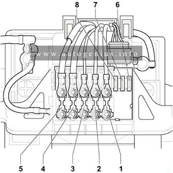
27 15 J538 – Fuel pump control unit
G6 – Fuel system pressurisation pump
J17 – Fuel pump control unit
J643 – Fuel supply relay (from May 2006)
28 10 Charging point for Mag- Lite electric torch (special vehicle interface) (up to May 2005)
30 U13 – Transformer with socket, 12V-230V (from May 2005)
Not assigned (from May 2006)
25 Special vehicles socket (not for USA/Canada ) (high; from November 2005)
29 10 J220/J623 – Motronic control unit
J248/J623 – Diesel direct injection system control unit
G70 – Air mass meter (AXX)
N79 – Heater element for crankcase breather (BUB, BMJ)
Not assigned (from 2006)
30 5 J234 – Airbag control unit (to May 2005)
K145 – Front passenger side airbag deactivated warning lamp (to May 2005)
10 N30 – Injector, cylinder 1 (from May 2005)
N31 – Injector, cylinder 2 (from May 2005)
N32 – Injector, cylinder 3 (from May 2005)
N33 – Injector, cylinder 4 (from May 2005)
20 N30 – Injector, cylinder 1
N31 – Injector, cylinder 2
N32 – Injector, cylinder 3
N33 – Injector, cylinder 4
N83 – Injector, cylinder 5
N84 – Injector, cylinder 6
J217 – Automatic gearbox control unit (from 2006)
J743 – Mechatronics for direct shift gearbox (from 2006)
31 5 F4 – Reversing light switch (up to May 2005)
J743 – Mechatronics for direct shift gearbox (up to May 2005)
20 V192 – Vacuum pump for brakes (from May 2005)
32 30 J388 – Rear left door control unit (window regulator) (up to May 2006)
J389 – Rear right door control unit (window regulator) (up to May 2006)
U13 – Transformer with socket, 12V-230 V (from May 2006)
U27 – Transformer with socket, 12V- 15 V, (USA/Canada) (from May 2006)
33 25 J245 – Sliding sunroof adjustment control unit
34 15 V125 – Driver seat lumbar support longitudinal adjustment motor
V126 – Front passenger seat lumbar support longitudinal adjustment motor
V129 – Driver seat lumbar support height adjustment motor
V130 – Front passenger seat lumbar support height adjustment motor
35 5 G273 – Interior monitoring sensor
G384 – Vehicle inclination sender
H12 – Alarm horn
Not assigned (from 2006)
36 20 V11 – Headlight washer system pump
J39 – Headlight washer system relay
37 30 J131 – Heated driver seat control unit
J132 – Heated front passenger seat control unit
38 10 J23 – Rotating light and siren system control unit (up to May 2005)
Not assigned (from May 2005)
J745 – Cornering light and headlight range control unit, on left headlight, (from May 2007)
20 J388 – Rear left door control unit (central locking), NAR, with alarm horn relay J641) (from May 2006)
J389 – Rear right door control unit (central locking), NAR, with alarm horn relay J641) (from May 2006)
J393 – Convenience system central control unit (only VR6) (from May 2006)
39 20 Not assigned (up to May 2005)
J217 – Automatic gearbox control unit (from May 2005)
Not assigned (from May 2006)
40 40 E16 – Heater/heat output switch (fresh air blower)
J301 – Air conditioning system control unit (fresh air blower)
5 E16 – Heater/heat output switch (fresh air blower) (high; from November 2005)
J301 – Air conditioning system control unit (fresh air blower) (high; from November 2005)
41 15 V12 – Rear window wiper motor (up to May 2006)
20 V12 – Rear window wiper motor (from May 2006)
J519 – Onboard supply control unit (double washer pump) (BSG J1) (from May 2006)
42 15 J729 – Double washer pump relay 1 (to May 2005)
J730 – Double washer pump relay 2 (to May 2005)
J519 – Onboard supply control unit (double washer pump) (BSG J1) (from May 2005)
20 U1 – Cigarette lighter (from May 2006)
U9 – Rear cigarette lighter (from May 2006)
U5 – 12 V socket (criminal investigation department) (from May 2006)
43 15 J345 – Trailer detector control unit
44 20 J345 – Trailer detector control unit
45 15 J345 – Trailer detector control unit
46 5 Z20 – Left washer jet heater element
Z21 – Right washer jet heater element
E94 – Heated driver seat regulator
E95 – Heated front passenger seat regulator
Not assigned (from May 2006)
47 5 J485 – Auxiliary heater operation relay
Not assigned (from May 2006)
48 10 Not assigned (to May 2005)
Charger for Mag-Lite and hand-held two-way radio (from May 2005)
49 5 E1 – Lighting switch
Not assigned (from May 2006)

Engine compartment

Fuse box diagram (low)

Volkswagen Jetta (V, Type 1K; 2005 - 2010)- fuse and relay box diagram - engine compartment (low)
Volkswagen Jetta (V, Type 1K; 2005 – 2010)- fuse and relay box diagram – engine compartment (low)


Assignment of the fuses and relays in the engine compartment (low)

No.
A
Function/component
F1 20 J393 – Convenience system central control unit
Not assigned (from May 2006)
F2 5 J527 – Steering column electronics control unit
F3 5 J519 – Onboard supply control unit
F4 30 J104 – ABS control unit
F5 15 J743 – Mechatronic control unit (up to May 2006), (from May 2007)
30 J743 – Mechatronic control unit (from May 2006)
J285 – Control unit in dash panel insert (from May 2006)
F6 5 J285 – Control unit in dash panel insert
F7 15 J608 – Special vehicle control unit
25 J608 – Special vehicle control unit (from May 2006)
30 J743 – Mechatronics control unit (0AM) (from May 2007)
F8 15
25
J503 – Control unit with display for radio and navigation
R – Radio
R – Preparation for radio and navigation system with TV (models for Japan)
F9 5 J412 – Mobile telephone operating electronics control unit
F10 5 J317 – Terminal 30 voltage supply relay
10 J623 – Engine control unit
5 J359 – Low heat output relay
F11 20 J364 – Auxiliary heater control unit
F12 5 J533 – Data bus diagnostic interface
F13 30 J623 – Engine control unit (only models with diesel engine)
J623 – Engine control unit (petrol) (from May 2007)
25 J623 – Petrol engine control unit (only models with petrol engine) (up to May 2007)
F14 20 N152 – Ignition transformer
N70-N323 – Ignition coils with output stage
F15 10 Z62 – Lambda probe heater 3
Z19 – Lambda probe heater
G39 – Lambda probe
G108 – Lambda probe 2 before catalytic converter
G130 – Lambda probe after catalytic converter
5 G131 – Lambda probe 2 after catalytic converter
G287 – Lambda probe 3 after catalytic converter
J17 – Fuel pump relay
J179 – Automatic glow period control unit
J360 – High heat output relay (370)
F16 30 J104 – ABS control unit
F17 15 H2 – Treble tone horn
H7 – Bass tone horn
J519 – Onboard supply control unit (from May 2006)
F18 30 J608 – Special vehicle control unit (up to May 2006)
R12 – Amplifier
F19 30 J400 – Wiper motor control unit
V216 – Driver side windscreen wiper motor
F20 40 Not assigned (up to May 2006)
J179 – Automatic glow period control unit (SDI) (from May 2006)
10 V50 – Continued coolant circulation pump (from May 2007)
F21 15 Z19 – Lambda probe heater (up to May 2006)
G39 – Lambda probe (up to May 2006)
G130 – Lambda probe after catalytic converter (up to May 2006)
J583 – NOx sensor control unit (up to May 2006)
10 Z28 – Lambda probe heater
G39 – Lambda probe
G130 – Lambda probe after catalytic converter (from May 2006)
J583 – NOx sensor control unit (from May 2006)
Z28 – Lambda probe heater (from May 2006)
20 V192 – Brake vacuum pump (from May 2007)
F22 5 F47 – Brake pedal switch (to November 2005)
G476 – Clutch position sender
F23 5 J299 – Secondary air pump relay (BSF)
10 N18 – Exhaust gas recirculation valve
N75 – Charge pressure control solenoid valve (up to May 2006)
N80 – Activated charcoal filter system solenoid valve 1 (from May 2006)
V144 – Fuel system diagnostic pump (BGQ,BGP)
N345 – Exhaust gas recirculation cooler changeover valve
N381 – Exhaust gas recirculation cooler changeover valve 2 (up to May 2006)
N276 – Fuel pressure regulating valve (from May 2006)
J623 – Engine control unit (from May 2006)
N156 – Variable intake manifold changeover valve (from May 2006)
15 N276 – Fuel pressure regulating valve (up to May 2006)
N218 – Secondary air inlet valve (from May 2006)
N276 – Fuel pressure regulating valve (from May 2007)
J623 – Engine control unit (from May 2007)
N156 – Variable intake manifold changeover valve (from May 2007)
F24 10 F265 – Map-controlled engine cooling system thermostat
J293 – Radiator fan control unit
N18 – Exhaust gas recirculation valve
N80 – Activated charcoal filter solenoid valve 1
N156 – Variable intake manifold changeover valve
N205 – Inlet camshaft control valve 1
N316 – Intake manifold flap valve
V157 – Intake manifold flap motor
F25 40 J519 – Onboard supply control unit (up to May 2006)
30 J519 – Onboard supply control unit (A/1) (from May 2006)
F26 40 J519 – Onboard supply control unit (up to May 2006)
30 J519 – Onboard supply control unit (D/1) (from May 2006)
F27 50 J179 – Automatic glow period control unit
40 J299 – Secondary air pump relay
F28 40 J681 – Terminal 15 voltage supply relay 2
F29 50 J496 – Additional coolant pump relay
S44 – Seat adjustment thermal fuse 1
F30 50 Not assigned (up to May 2006)
J59 – X-contact relief relay (from May 2006)
40 J519 – Onboard supply control unit (I/1) (from May 2007)
Relay
A1 Terminal 30 voltage supply relay -J317- (458)
Terminal 30 voltage supply relay -J317- (100)
Terminal 30 voltage supply relay -J317- (370)
A2 Secondary air pump relay -J299- (100)
Sensor for current measurement -G582- (488; up to May 2006, only engine code BLG)
Wiring bridge (only models with diesel engine)

Relay code number 100 is replaced by relay code number 370 depending on production.


Volkswagen Jetta (V, Type 1K; 2005 - 2010)- fuse and relay box diagram - engine compartment
Volkswagen Jetta (V, Type 1K; 2005 – 2010)- fuse and relay box diagram – engine compartment


Assignment of the fuses and relays in the engine compartment

No.
A
Function/component
1 150 C – Alternator (90A/120A)
200 C – Alternator (140A)
2 80 J500 – Power steering control unit
V187 – Electromechanical power steering motor
3 50 J293 – Radiator fan control unit
V7 – Radiator fan
V177 – Radiator fan 2
4 40
Special equipment (up to May 2006)
J359 – Low heat output relay (1st stage), (from December 2006)
Z35 – Auxiliary air heater element (from December 2006)
5 100
Fuses on fuse holder C, on left under dash panel SC43-SC45, SC28, SC22, SC18, SC19, SC12, (up to November 2005)
Fuses on fuse holder C, on left under dash panel SC43-SC45, SC28, SC22, SC15-SC20, SC 12, SC22-SC27, SC19, SC38, (from November 2005)

J604 – Auxiliary air heater control unit (up to November 2005)
Z35 – Auxiliary air heater element (up to November 2005)
Optional equipment (from November 2005)

6 80 Fuses on fuse holder C, on left under dash panel SC43-SC45, SC28, SC22, SC18, SC19, SC12
J360 – High heat output relay (1st and 3rd stages), (from December 2006)

Z35 – Auxiliary air heater element (from November 2006)
100 J604 – Auxiliary air heater control unit (from November 2005)
Z35 – Auxiliary air heater element (from November 2005)
Optional equipment
7 50 Trailer operation
40 Special equipment, disabled persons
30 Special equipment, criminal investigation department

Fuse box diagram (high)

Volkswagen Jetta (V, Type 1K; 2005 - 2010)- fuse and relay box diagram - engine compartment (high)
Volkswagen Jetta (V, Type 1K; 2005 – 2010)- fuse and relay box diagram – engine compartment (high)


Assignment of the fuses and relays in the engine comparment (high)

No.
A
Function/component
F1 30 J104 – ABS with EDL control unit
F2 30 J104 – ABS with EDL control unit
F3 20 J393 – Convenience system central control unit
V217 – Front passenger side wiper motor (from May 2005)
Not assigned (from November 2005)
F4 5 J519 – Onboard supply control unit
F5 20 H2 – Treble tone horn (up to May 2005)
H7 – Bass tone horn (up to May 2005)
15 J519 – Onboard supply control unit (horn) (from May 2005)
F6 5 N276 – Fuel pressure regulating valve (up to May 2005)
15 N276 – Fuel pressure regulating valve (from May 2005)
J17 – Fuel pump (from May 2007)
20 N152 – Ignition transformer (up to May 2005)
N… – Ignition coils 1-4 with output stage (up to May 2005)
F7 5 F47 – Cruise control system brake pedal switch
G476 – Clutch position sender
Not assigned (from November 2005)
40 SF2 – Fuse 2 on fuse holder F (rear battery) (from May 2007)
F8 10 F265 – Map-controlled engine cooling system thermostat
N205 – Inlet camshaft control valve 1
N80 – Activated charcoal filter solenoid valve 1 (pulsed)
N18 – Exhaust gas recirculation valve
N316 – Intake manifold flap air control valve
V157 – Intake manifold flap motor
N79 – Crankcase breather heater element
N156 – Variable intake manifold changeover valve
J293 – Radiator fan control unit
Not assigned (from May 2005)
15 R190 – Digital radio satellite receiver (from May 2007)
F9 10 J583 – NOx sensor control unit (up to May 2005)
J179 – Automatic glow period control unit (up to May 2005)
J17 – Fuel pump relay (up to May 2005)
N249 – Turbocharger air recirculation valve (from May 2005)
N80 – Activated charcoal filter solenoid valve 1 (from May 2005)
N75 – Charge pressure control solenoid valve (from May 2005)
F10 10 G130 – Lambda probe after catalytic converter (up to May 2005)
G131 – Lambda probe 2 after catalytic converter (up to May 2005)
N18 – Exhaust gas recirculation valve (up to May 2005)
N75 – Charge pressure control solenoid valve (up to May 2005)
N345 – Exhaust gas recirculation cooler changeover valve (up to May 2005)
J299 – Secondary air pump relay (up to May 2005)
Not assigned (from May 2005)
V144 – Fuel system diagnostic pump (USA/Canada) (from November 2005)
G42 – Intake air temperature sender (from May 2007)
G70 – Air mass meter (from May 2007)
F11 25 J220 – Motronic control unit (up to May 2005)
30 J361 – Simos control unit (up to May 2005)
J248 – Diesel direct injection system control unit (up to May 2005)
10 Z19 – Lambda probe heater (from May 2005)
Z28 – Lambda probe 2 heater 2 (from May 2007)
F12 15 G39 – Lambda probe (AXW, BAG, BCA, BKG, BLP, BLX and BLY) (up to May 2005)
G108 – Lambda probe 2 (AXW, BLX and BLY) (up to May 2005)
G130 – Lambda probe after catalytic converter (BCA) (up to May 2005)
J583 – NOx sensor control unit (BAG, BKG and BLP) (up to May 2005)
10 Z29 – Lambda probe 1 heater after catalytic converter (from May 2005)
Z30 – Lambda probe 2 heater after catalytic converter (from May 2007)
F13 15 J217 – Automatic gearbox control unit (up to May 2005)
J743 – Mechatronics for dual clutch gearbox
30 J743 – Mechatronic control unit (from May 2007)
F14 Not assigned
F15 40 B – Starter (terminal 50) (up to May 2005)
10 V50 – Coolant circulation pump (from May 2005)
F16 15 J527 – Steering column electronics control unit (up to May 2005)
5 J104/J527 – Steering column control unit (from May 2005)
F17 10 J285 – Display control unit in dash panel insert (up to May 2005)
5 J285 – Control unit in dash panel insert (from May 2005)
F18 30 J608 – Special vehicle control unit (up to May 2005)
R12 – Amplifier (from May 2005)
J608 – Control unit for special vehicles (from May 2007)
F19 15 R – Radio
J503 – Control unit with display for radio and navigation system (up to May 2005)
R19 – Digital satellite radio (from May 2007)
F20 10 J412 – Mobile telephone operating electronics control unit (telephone /preparation for telephone)
J503 – Control unit with display for radio navigation system (from May 2005)
5 J412 – Mobile telephone operating electronics control unit (from November 2005)
F21 Not assigned
F22 Not assigned
F23 10 Not assigned (up to May 2005)
J623 – Engine control unit (from May 2005)
J271 – Motronic current supply relay (100) (from May 2005)
5 J623 – Engine control unit (from November 2005)
F24 10 J533 – Data bus diagnostic interface (up to May 2005)
5 J533 – Data bus diagnostic interface (from May 2005)
F25 40 Not assigned (up to May 2007)
J519 – Onboard supply control unit (A1) (from May 2007)
F26 10 J220 – Motronic control unit (up to May 2005)
Not assigned (from May 2005)
5 J248 – Diesel direct injection system control unit (up to May 2005)
J317 – Terminal 30 voltage supply relay (up to May 2007)
40 J519 – Onboard supply control unit (D1) (from May 2007)
F27 10 N79 – Heater element for crankcase breather (up to May 2005)
Not assigned (from May 2005)
F28 20 J217 – Automatic gearbox control unit (up to May 2005)
F125 – Multifunction switch (up to May 2005)
25 J623 – Engine control unit (from May 2005)
F29 20 N… – Ignition coils 1-4 with output stage (up to May 2005)
N… – Injectors cylinders 1-4 (up to May 2005)
5 J496 – Additional coolant pump relay (from May 2005)
J299 – Secondary air pump relay (from May 2005)
F30 20 J162 – Heater control unit (up to May 2005)
J485 – Auxiliary heater operation relay (from May 2005)
F31 25 V – Windscreen wiper motor (up to May 2005)
30 V – Windscreen wiper motor (from May 2005)
F32 10 N… – Injectors (up to May 2005)
Not assigned (from May 2005)
F33 15 G6 – Fuel system pressurisation pump (up to May 2005)
Not assigned (from May 2005)
F34 Not assigned
F35 Not assigned
F36 Not assigned
F37 Not assigned
F38 10 V48 – Left headlight range control motor (up to May 2005)
V49 – Right headlight range control motor (up to May 2005)
J293 – Radiator fan control unit (from May 2005)
N205 – Exhaust camshaft control valve 1 (from November 2005)
N112 – Secondary air inlet valve (from May 2007)
N321 – Exhaust flap 1 valve (from May 2007)
N320 – Secondary air inlet valve 2 (from May 2007)
V144 – Diagnosis pump for fuel system (from May 2007)
N80 – Activated charcoal filter solenoid valve 1 (from May 2007)
N156 – Secondary air inlet valve (from May 2007)
N318 – Exhaust camshaft control valve 1 (from May 2007)
F39 5 G226 – Oil level and oil temperature sender (up to November 2005)
F – Brake light switch (up to November 2005)
F47 – Brake pedal switch (from November 2005)
G476 – Clutch position sender (from November 2005)
F40 20 Dash panel fuse holder (SC1-SC6, SC7-SC11, SC29-SC31) (up to May 2005)
N70 – Ignition coil 1 with output stage (from May 2005)
N127 – Ignition coil 2 with output stage (from May 2005)
N291 – Ignition coil 3 with output stage (from May 2005)
N292 – Ignition coil 4 with output stage (from May 2005)
F41 Not assigned
F42 10 G70 – Air mass meter (AZV, BKC, BKD, BDK, BJB)
J757 – Engine component current supply relay (from November 2005)
5 J49 – Electric fuel pump 2 relay (BGU, BCA)
J271 – Motronic current supply relay (to November 2005)
F43 30 Not assigned (up to May 2005)
N70 – Ignition coil 1 with output stage (from May 2005)
N127 – Ignition coil 2 with output stage (from May 2005)
N291 – Ignition coil 3 with output stage (from May 2005)
N292 – Ignition coil 4 with output stage (from May 2005)
N323 – Ignition coil 5 with output stage (from May 2005)
N324 – Ignition coil 6 with output stage (from May 2005)
F44 Not assigned
F45 Not assigned
F46 Not assigned
F47 40 J519 – Onboard supply control unit (up to November 2005)
30 J519 – Onboard supply control unit (D/1 left) (from November 2005)
F48 40 J519 – Onboard supply control unit (up to November 2005)
30 J519 – Onboard supply control unit (A/1 right) (from November 2005)
F49 40 Not assigned (up to May 2005)
J681 – Terminal 15 voltage supply relay 2 (from May 2005)
SF2 – Fuse in fuse holder F (rear battery) (from November 2005)
J519 – Onboard supply control unit (L1) (from November 2005)
F50 Not assigned
F51 50 Q10 – Glow plug 1 (up to May 2005)
Q11 – Glow plug 2 (up to May 2005)
Q12 – Glow plug 3 (up to May 2005)
Q13 – Glow plug 4 (up to May 2005)
40 J299/V101 – Secondary air pump relay (from May 2005)
F52 50 J519 – Onboard supply control unit SC40-SC42, SC46, SC47, SC49 (up to May 2005)
40 J59 – X-contact relief relay (from May 2005)
F53 50 Safety cutout for seat adjustment
S44 – Seat adjustment thermal fuse 1, SB111 – Positive connection 1 (30a) (from November 2005)
F54 50 J293 – Radiator fan control unit (up to May 2005)
Not assigned (from May 2005)
Relay
A1 Terminal 15 voltage supply relay -J329- (433) (up to May 2005)
Motronic current supply relay -J271- (100) (up to November 2005)
Engine components current supply relay -J757- (167) (from November 2005)
A2 Terminal 50 voltage supply relay -J682- (433) (up to May 2005)
Additional coolant pump relay -J496- (100) (from May 2005)
A3 Current supply relay for engine components -J757- (167) (up to May 2005)
Not assigned (from November 2005)
A4 Terminal 30 voltage supply relay -J317- (458) (up to May 2005)
Engine components current supply relay -J757- (167) (up to November 2005)
Motronic current supply relay -J271- (100) (from May 2005)


Volkswagen Jetta (V, Type 1K; 2005 - 2010)- fuse and relay box diagram - engine compartment
Volkswagen Jetta (V, Type 1K; 2005 – 2010)- fuse and relay box diagram – engine compartment


Assignment of the fuses and relays in the engine comparment

No.
A
Function/component
1 150 C – Alternator (90A/120A)
200 C – Alternator (1401A)
TV2 – Terminal 30 wiring junction (rear battery)
2 80 J500 – Power steering control unit
V187 – Electromechanical power steering motor
3 50 J293 – Radiator fan control unit
V7 – Radiator fan
V177 – Radiator fan 2 (500 W)
4 80
Not assigned (up to May 2005)
Fuses on fuse holder C, on left under dash panel: SC32-SC 37, Driver seat adjustment thermal fuse 1 – 30A (from May 2005)
Not assigned (from November 2005)
5 50
80
Fuses on fuse holder C, on left under dash panel SC12-SC17, SC19, SC22-SC27, SC32-SC38, SC43-SC45 (up to May 2005), (from May 2007)
100 J604 – Auxiliary air heater control unit (from May 2005)
Z35 – Auxiliary air heater element (from May 2005)
50 Fuses on fuse holder C, on left under dash panel SC12-SC17, SC19, SC22-SC27, SC32-SC38, SC43-SC45 (from November 2005)
6 125
SF1 – Fuse 1 on fuse holder F (rear battery) (up to May 2005), (from November 2005)
100
80
Fuses on fuse holder C, on left under dash panel: SC18-SC20, SC22-SC28, SC43-SC45 optional equipment (from May 2005)
7 50
Not assigned (up to May 2005), (from November 2005)
Fuses on fuse holder C, on left under dash panel: SC22-SC27 (from May 2005)

Relay carrier on onboard supply control unit (left under dash panel)

Fuse box diagram

Volkswagen Jetta (V, Type 1K; 2005 - 2010)- fuse and relay box diagram - dash panel
Volkswagen Jetta (V, Type 1K; 2005 – 2010)- fuse and relay box diagram – dash panel


Assignment of the fuses and relays in the instrument panel

No.
A
Function/component
A 30 Seat adjustment thermal fuse 1 -S44- (from May 2004)
B 30 Seat adjustment thermal fuse 1 -S44- (up to April 2004)
Relay
1 Fresh air blower relay -J13- (53) (only with auxiliary heater)
Low heat output relay -J359- (373)
2 Auxiliary heater operation relay -J485- (449)
High heat output relay -J360- (370)
Secondary air pump relay -J299- (100)
3 Headlight washer system relay -J39- (53)
Terminal 50 voltage supply relay -J682- (449 / 53)
4 Additional coolant pump relay -J496- (449) (BLG)
Fuel supply relay -J643- (449) (BCA)
Fuel pump relay -J17- (449)
Headlight washer system relay -J39- (53)
5 Terminal 50 voltage supply relay -J682- (433 / 53)
Fuel pump relay -J17- (449) (J17- and -J485- are mini-relays and can be found on a relay slot)
Auxiliary heater operation relay -J485- (449) (J17- and -J485- are mini-relays and can be found on a relay slot)

Relay assignment on relay carrier on onboard supply control unit

Fuse box diagram

Volkswagen Jetta (V, Type 1K; 2005 - 2010)- fuse and relay box diagram - relay assignment on relay carrier on oboard supply control unit
Volkswagen Jetta (V, Type 1K; 2005 – 2010)- fuse and relay box diagram – relay assignment on relay carrier on oboard supply control unit


Assignment of the fuses and relays

No.
Relay
1 Fresh air blower relay -J13- (up to May 2005)
Terminal 15 voltage supply relay 2 -J681-
2 Heated exterior mirror relay -J99- (449)
3 Heated rear window relay -J9- (53)
4 Horn relay -J413- (449)
5 X-contact relief relay -J59- (460)
6 Double washer pump relay 2 -J730- (404)
7 Double washer pump relay 1 -J729- (404)
8 Not assigned
9 Terminal 30 voltage supply relay 2 -J689- (449)

Additional relay carrier, under box on left in engine compartment

Volkswagen Jetta (V, Type 1K; 2005 - 2010)- fuse and relay box diagram - engine compartment - additional relay carrier
Volkswagen Jetta (V, Type 1K; 2005 – 2010)- fuse and relay box diagram – engine compartment – additional relay carrier


Assignment of the fuses and relays in engine compartment

No.
Relay
1 Automatic glow period control unit -J179- (461) / (457)

WARNING: Terminal and harness assignments for individual connectors will vary depending on vehicle equipment level, model, and market.

Volkswagen Jetta (A6; 2010 – 2017) – fuse and relay box diagram

Volkswagen Jetta (A6; 2010 – 2017) – fuse and relay box diagram

Year of production: 2010, 2011, 2012, 2013, 2014, 2015, 2016, 2017


This article covers the sixth-generation Volkswagen Jetta (A6, Typ 1B), produced from 2010 to 2017. It provides fuse box diagrams for the 2010, 2011, 2012, 2013, 2014, 2015, 2016, and 2017 models, details the locations of the fuse panels inside the vehicle, and explains the function of each fuse (fuse layout) and relay.


Passenger Compartment Fuse Box

Fuse Box Location

The fuse box is located behind the cover on the driver’s side. Pull the lower part of the cover in the direction of the arrow and remove the cover from the bottom. On the inside of the cover there are plastic tweezers for removing and inserting fuses.

Volkswagen Jetta (A6; 2010 - 2017) - fuse and relay diagram - passenger compartment
Volkswagen Jetta (A6; 2010 – 2017) – fuse and relay diagram – passenger compartment


Fuse Box Diagram (-SC-)

Volkswagen Jetta (A6; 2010 - 2017) - fuse and relay diagram - passenger compartment (holder C)
Volkswagen Jetta (A6; 2010 – 2017) – fuse and relay diagram – passenger compartment (holder C)


Assignment of the fuses in the instrument panel (holder C)

Amps Function/Component
F1 10A 2014-2017:
Left washer nozzle heater
Right washer nozzle heater
F2 5A/7,5A Electronic steering column lock control module
F3 10A Instrument cluster control module
F4 2A/10A 2012-2017:
Telephone Transceiver
Compass magnetic field sensor (vehicles equipped with Start/Stop)
F5 7.5A 2012-2017: Left rear fog lamp bulb
F6 10A Vehicle electrical system control module (T73a/66) (interior lamp, AW0 only)
Rearview camera (2014-2017)
F7 5A Fog lamp relay (AW0 only)
Instrument panel and switch illumination dimmer switch (AW0 only)
License plate lamp
Vehicle electrical system control module (T52c/27), (AW1 only)
F8 7.5A Windshield and headlamp washer pump switch (AW0 only)
Windshield washer pump (AW0 only)
Vehicle electrical system control module (T73b/61), (AW0 only)
F8 not used (AW1 only)
F9 5A/15A Arbag control module
Airbag Control Module
Front passenger airbag “disabled” indicator lamp
Passenger occupant detection system control module
F10 10A Right steering column switch (T10ls/3) (AW0 only)
F11 10A 2012-2017: Left front headlamp (HID headlamp)
F12 10A 2012-2017: Right front headlamp (HID headlamp)
F13 5A Automatic dimming interior rearview mirror
Light recognition sensor
Parking aid control module
Ar quality sensor
High pressure sensor
Climatronic control module
Tire pressure monitoring button
ASR/ESP button
Back-up lamp switch
Start/Stop mode switch
28-pin connector (T28/10)
Mirror adjusting switch
Exterior rearview mirror heating switch
AC compressor control module (T14hy/14) (Engine code CNLA)
Cornering lamp and headlamp range control module
F14 10A Left steering column switch (T16ls/1) (AW0 only)
ABS control module T26/20 / T47/8
Light switch (T10h/4) (AW1 only)
Arbag spiral spring/return spring with slip ring (T16k/14)
Fuel pump control module
Towing recognition control module (T12a/2)
Voltage stabilizer
Converter with socket, 12V-230V (T3wr/3)
Data bus on board diagnostic interface (AW1 only)
Instrument cluster control module
Selector lever sensor system control module
Tiptronic switch (T10s/9)
Power steering control module (T6z/1)
Oil level thermal sensor (T6z/4)
Hybrid battery unit (T14ax/7) (Engine code CNLA)
Electric drive power and control electronics (T28jx/56) (Engine code CNLA)
F15 10A 16-pin connector (diagnostic connection)
Instrument panel and switch illumination dimmer switch
Headlamp range control adjuster (AW1 only)
Fresh air blower relay
Mass airflow sensor
Positive crankcase ventilation heating element –
Structure borne sound control module
Left front headlamp
Left headlamp beam adjustment motor
Right front headlamp
Right headlamp beam adjustment motor
Vehicle electrical system control module (T73a/44)
F16 10A Auxiliary engine coolant pump relay
Fuel pump control module
Engine control module
Electric drive button (Engine code CNLA)
F17 10A 2012-2017:
Anti-theft alarm system horn (Running change)
Anti-theft alarm system interior sensor (Running change)
Anti-theft alarm system alarm (Running change)
F18 15A Left front headlamp
Left low beam headlamp bulb (vehicles with China equipment)
F19 15A Right front headlamp
Right low beam headlamp bulb (vehicles with China equipment)
F20 10A Ignition/starter switch (T10/10) (AW0 only)
Tiptronic switch
Automatic transmission control module
Selector lever sensor system control module
Climatronic control module
Auxiliary engine coolant heater radio frequency receiver
F21 15A/20A 2012-2017:
Vehicle electrical system control module (T73a/73), (AW0 only)
Dual tone horn relay (AW1 only)
High tone horn (AW1 only)
Low tone horn (AW1 only)
F22 20A/10A/7.5A Ignition/starter switch (AW0 only)
Converter box (AW0 only)
Interior monitoring sensor
Aarm horn relay
Aarm horn
Dual tone horn relay (2010-1011)
F23 10A Vehicle electrical system control module (T73b/39) (AW0 only)
16-pin connector (diagnostic connection)
Light switch (AW1 only)
Rain/light recognition sensor
Compass magnetic field sensor (vehicles without Start/Stop)
F24 10A Vehicle electrical system control module (T73a/64) (AW0 only)
Access/start authorization control module
F25 15A Automatic transmission control module
Selector lever sensor system control module
Multifunction switch
F26 15A Brake system vacuum pump
F27 1A 2012-2017: Arbag spiral spring/return spring with slip ring (T16k/1)
F28 40A Auxiliary heater operation relay
F29 1A Vehicle electrical system control module (T73b/51) (AW0 only)
Ignition/starter switch (AW0 only)
Converter box (AW0 only)
F30 20A Cigarette lighter
12V socket
12V socket 2
Blocking diode
F31 30A Light switch (T17/1) (AW0 only)
F32 20A Light switch (T17/2) (AW0 only)
F33 40A Heater/heat output switch
Fresh air blower relay
AC control module
Fresh air blower switch
F34 15A Left high beam headlamp bulb (AW0 only)
Right high beam headlamp bulb (AW0 only)
Instrument cluster control module (AW0 only)
F35 10A Steering column electronics control module (AW1 only)
Data bus on board diagnostic interface (AW1 only)
Instrument cluster control module (2010-2011)
Signal horn activation (2010-2012)
F36 25A Vehicle electrical system control module (T73a/16) (AW0 only) (T52b/1) (AW1 only)
Vehicle electrical system control module (T73a/61) (AW0 only) (Running change)
F37 15A Left front headlamp
Left daytime running lamp bulb
F38 15A Right front headlamp
Right daytime running lamp bulb
F39 20A Low beam relay
F40 15A Towing recognition control module (T12a/9)
F41 15A Towing recognition control module (T12a/12)
F42 20A Towing recognition control module (T12a/11)
F43 30A Front passenger door control module
F44 25A/30A Rear window defogger relay (AW1 only)
Rear window defogger
Vehicle electrical system control module (T73b/67) (AW0 only)
F45 30A Driver door control module
Front passenger door control module (vehicles with China equipment)
F46 30A Left rear door control module
Right rear door control module
F47 15A Fuel pump control module
Fuel pump relay
Fuel primer relay
F48 20A Vehicle electrical system control module
F49 40A Fresh air blower
Climatronic control module
A/C control module
F50 30A Front seat heating control module
F51 20A Sunroof control module
F52 20A 2010-2012:
Dual tone horn relay

2013-2017:
Headlamp Washer Relay
Headlamp washer pump
F53 15A 2010-2012:
Front seat heating control module

2013-2017:
Driver seat lumbar support adjustment switch
F54 15A Fog lamp relay
F55 20A Light switch (T17/15) (AW0 only)
Left steering column switch (T16ls/10) (AW0 only)
F56 10A 2013-2017:
Hybrid battery unit (T14ax/5) (Engine code CNLA)
Electric drive power and control electronics (T28jx/55) (Engine code CNLA)
F57 15A/25A Radio
Radio/Navigation Display Control Module
F58 1A/30A Telephone Transceaver (2010-2011)
Converter with socket 12V-230V
F59 15A/30A 2010-2012:
Amplifier

2013-2017:
Fan activation relay (Engine code CNLA)
Battery fan 1 (Engine code CNLA)
F60 30A Auxiliary heater control module
20A Driver power seat adjustment circuit breaker 1 (it is located above relay carrier)


Relays

The relay carrier is above the fuse panel.

Volkswagen Jetta (A6; 2010 - 2017) - fuse and relay diagram - passenger compartment (relays)
Volkswagen Jetta (A6; 2010 – 2017) – fuse and relay diagram – passenger compartment (relays)


15-pin relay carrier (2010-2011)
Volkswagen Jetta (A6; 2010 - 2017) - fuse and relay diagram - passenger compartment (15-pin relay carrier)
Volkswagen Jetta (A6; 2010 – 2017) – fuse and relay diagram – passenger compartment (15-pin relay carrier)


Assignment of the fuses in the relay box (2010 – 2011)

Description
R1 Converter box (E-Box Low, (AWO))
R2 Fresh air blower relay
R3 Auxiliary heater operation relay -J485- (449)
R4 Fuel Pump Relay
Engine Component Power Supply Relay
Auxiliary engine coolant pump relay
R5 Low beam relay (E-Box Low, (AWO))
R6 Fresh air blower relay
R7 Terminal 75 power supply relay 1
R8 Dual tone horn relay
Headlamp washer relay
R9 Power Supply Relay (terminal 50) -J682- (643)
R10 Terminal 15 power supply relay 2 -J681- (643)
R11 Rear window defogger relay -J9- (449)
R12 Fuel pump relay 2
Heat resistance relay
Cold start injector relay
Fuel primer relay
R13 Power Supply Relay (terminal 50)
R14 Terminal 15 power supply relay
R15 Fog lamp relay
 
12-pin relay carrier (2012-2017)
Volkswagen Jetta (A6; 2010 - 2017) - fuse and relay diagram - passenger compartment (15-pin relay carrier)
Volkswagen Jetta (A6; 2010 – 2017) – fuse and relay diagram – passenger compartment (15-pin relay carrier)


Assignment of the fuses in the relay box (2012 – 2017) 

Description
R1 Dual tone horn relay
Alarm horn relay (USA and Mexico, E-Box Low)
Headlamp washer relay
R2 Power Supply Relay (terminal 50)
Starter relay 2
Driver power window opening relay (E-Box high, since 2013)
Driver power window closing relay (E-Box high, since 2013)
R3 Cold start injector relay (since 2013)
Secondary air injection pump relay (CNLA)
Fuel pump relay 2
Front passenger power window opening relay (E-Box high, since 2013)
Heat resistance relay
Front passenger power window closing relay (E-Box high, since 2013)
R4 Coolant circulation pump relay (up to 2012)
Fuel Pump Relay
Auxiliary engine coolant pump relay
Fuel primer relay
Engine Component Power Supply Relay (E-Box high, since 2013)
R5 Terminal 75 power supply relay 1 (up to 2012)
R6 Power Supply Relay (terminal 50)
Starter relay 1
R7 Terminal 15 power supply relay (E-Box Low)
Auxiliary heater operation relay (E-Box high)
Power window relay (E-Box high, since 2013)
R8 Low beam relay (E-Box Low)
Rear window defogger relay (E-Box high)
R9 Terminal 15 power supply relay 2
R10 Terminal 75 power supply relay 1
R11 Fog lamp relay (E-Box Low)
Fresh air blower relay (E-Box high)
Fan activation relay (hybrid)
R12 Converter box (E-Box Low)
R13 Power Supply Relay (terminal 50)
R14 Terminal 15 power supply relay
R15 Fog lamp relay


Engine Compartment Fuse Box

Fuse Box Location

Move the release tabs in the direction of the arrows to unlock the fuse box cover.

Volkswagen Jetta (A6; 2010 - 2017) - fuse and relay location - engine compartment
Volkswagen Jetta (A6; 2010 – 2017) – fuse and relay location – engine compartment

Fuse Box Diagram (-SB-)

Volkswagen Jetta (A6; 2010 - 2017) - fuse and relay diagram - engine compartment
Volkswagen Jetta (A6; 2010 – 2017) – fuse and relay diagram – engine compartment


Assignment of the fuses in the engine compartment

Amps Function/Component
F1 Not used
F2 10A/15A Engine control module
Engine component power supply relay
F3 5A/10A Coolant fan control module
Relay for low heat output
Relay for high heat output
F4 5A/10A/15A Oxygen sensor heater
Heater for oxygen sensor 1 after catalytic converter
High temperature circuit coolant pump (Engine codes CNLA, CRJA)
Low temperature circuit coolant pump
F5 5A/10A/20A Oxygen sensor heater
Oxygen sensor 2 heater (Engine codes CNLA, CRJA)
Leak detection pump
Wastegate bypass regulator valve
EGR cooler switch-over valve
Positive crankcase ventilation heating element
Mass airflow sensor (Engine code CFFB)
Vacuum pump relay
Brake system vacuum pump
F6 5A/10A/15A/20A Leak detection pump
EVAP canister purge regulator valve 1
Tank switch-off valve
Secondary air injection pump relay
F6 5A/10A/15A Water pump
Auxiliary heater heating element
Relay for low heat output
Relay for high heat output
F7 20A Petrol:
Ignition coil 1~4 with power output stage
F7 5A Diesel:
Fuel pressure regulator valve
Fuel metering valve
F8 10A Throttle valve control module
Wastegate bypass regulator valve
EVAP canister purge regulator valve 1
Camshaft adjustment valve 1
Turbocharger recirculation valve
Intake manifold runner control valve
Exhaust camshaft adjustment valve 1 (Engine codes CNLA, CRJA)
Oil pressure regulation valve (Engine codes CNLA, CRJA)
Decoupler pressure actuator (Engine codes CNLA, CRJA)
Refrigerant cut-off valve (Engine codes CNLA, CRJA)
F9 5A/15A Secondary air injection sensor 1
Secondary air injection sensor 2
Automatic glow time control module
Fuel pump relay 2
Fuel pump relay
EVAP canister purge regulator valve 1
Camshaft adjustment valve 1
Fuel pressure regulator valve
After-run coolant pump
Coolant circulation pump relay
Engine coolant circulation pump 2
F10 5A Brake lamp switch
Clutch position sensor
Auxiliary engine coolant pump relay
Brake booster relay (Engine codes CNLA, CRJA)
Speed sensor
F11 Not used
F12 5A Ignition coil 1~4 with power output stage
After-run coolant pump
F13 5A/20A Auxiliary engine coolant pump relay
Water pump
Brake booster relay (Engine codes CNLA, CRJA)
Brake system vacuum pump (Engine codes CNLA, CRJA)
F14 5A Engine control module
Main relay
F15 30A Voltage stabilizer
F16 30A ABS control module
F17 30A DSG transmission Mechatronic
F18 20A DSG transmission Mechatronic
F19 1A Vehicle electrical system control module (T52a/24) AW1, (T73b/59) AW0
F20 30A Vehicle electrical system control module (AW0)
Wiper/washer intermittent relay (AW1)
Wiper motor change-over relay 1 (AW1)
Wiper motor change-over relay 2 (AW1)
F21 50A Secondary air injection pump motor
F22 40A Auxiliary heater heating element
F23 40A ABS control module
F24 50A Towing recognition control module
F25 50A Terminal 15 power supply relay
Terminal 15 power supply relay 2
F26 50A/40A Automatic glow time control module
Secondary air injection pump relay
Secondary air injection pump motor (Engine codes CNLA, CRJA)
F27 50A/60A Coolant fan
F28 40A Vehicle electrical system control module (AW1)
F29 40A Vehicle electrical system control module (AW1)
F30 50A Terminal 75 power supply relay 1
F31 30A Amplifier
F32 40A Auxiliary heater heating element
508   Threaded connection (30) on the E-box
SA1 200A Without Hybrid system:
Generator
With Hybrid system:
Electric drive power and control electronics
Voltage converter
SA2 Not used
SA3 80A Steering
SA4 80A Without Hybrid system:
Interior terminal 30 power supply SC fuses
R1   Wiper motor change-over relay 1 / Not used (AW0)
R2   Wiper motor change-over relay 2 / Not used (AW0)
R3   Main relay
Terminal 30 power supply relay
Fuel primer relay
R4   Relay for low heat output
Coolant circulation pump relay (Running change)
Auxiliary engine coolant pump relay
R5   Relay for high heat output
Secondary air injection pump relay (gasoline)
Brake booster relay (Hybrid, with auxiliary heater)
R6   Automatic glow time control module
Brake booster relay (Hybrid, without auxiliary heater)

WARNING: Terminal and harness assignments for individual connectors will vary depending on vehicle equipment level, model, and market.

Chevrolet Cruze (J300; 2008 – 2016) – fuse and relay box diagram

Chevrolet Cruze (J300; 2008 – 2016) – fuse and relay box diagram

Year of production: 2008, 2009, 2010, 2011, 2012, 2013, 2014, 2015, 2016


This article focuses on the first-generation Chevrolet Cruze (J300), manufactured between 2008 and 2016. It includes fuse box diagrams for the 2008 to 2016 models, provides details on the locations of the fuse panels inside the vehicle, and explains the function and layout of each fuse and relay.

Engine compartment fuse box

Fuse box diagram

Chevrolet Cruze (J300; 2008 - 2016) - fuse and relay box diagram - engine compartment
Chevrolet Cruze (J300; 2008 – 2016) – fuse and relay box diagram – engine compartment


Assignment of the fuses and relay in the engine compartment

No.
A
Description
1 15 Transmission Control Module
2 15 Engine Control Module
3 N/A Not Used
5 15 Transmission Control Module, Engine Control Module, Mass Air Flow/Intake Air Temperature Sensor, Output Speed Sensor
6 30 Windshield Wiper Relays
7 N/A Not Used
8 15 Fuel injectors
9 15 Ignition Coil, Fuel Injectors
10 15 Engine Control Module, Output Speed Sensor
11 10 Heated Oxygen Sensors
12 30 Starter Motor
13 7.5 Evaporative Emission (EVAP) Canister Vent Solenoid Valve
14 N/A Not Used
15 N/A Not Used
16 7.5 Air Quality Sensor
17 5 Inflatable Restraint Sensing and Diagnostic Module
18 10 Fuel Pump Control Module
19 N/A Not Used
20 20 Fuel Pump Relay
21 30 Windows Motors, Front Door
22 N/A Not Used
23 N/A Not Used
24 30 Windows Motors, Front Door
25 N/A Not Used
26 40 Electronic Brake Control Module (EBCM)
27 30 Remote Control Door Lock Receiver
28 40 Rear Demister Grid
29 N/A Not Used
30 15 Electronic Brake Control Module (EBCM)
31 20 Body Control Module
32 20 Body Control Module
33 30 Heated Seat Control Module
34 25 Sunroof Control Module
35 30 Audio Amplifier
36 N/A Not Used
37 10 Headlamp – Right Main beam
38 10 Headlamp – Left Main beam
39 N/A Not Used
40 N/A Not Used
41 N/A Not Used
42 20/30 Cooling Fan Relays, Cooling Fan Motor
43 N/A Not Used
44 N/A Not Used
45 30/40 Cooling Fan High Speed Relay, Cooling Fan Motor
46 10 Cooling Fan Relays
47 10 Heated Oxygen Sensors, Throttle Body
48 15 Fog Lights, Front
49 N/A Not Used
50 N/A Not Used
51 15 Horn
52 5 Instrument Cluster
53 10 Inside Rearview Mirror
54 5 Headlamp Switch, Electrical Auxiliary Heater, HVAC Control Module
55 7.5 Window Switches, Front, Mirror Switch
56 15 Windscreen Washer Pump
57 15 Steering Column Lock Control Module
58 N/A Not Used
59 30 Fuel Heater
60 7.5 Outside Rearview Mirrors
61 N/A Not Used
62 10 A/C Compressor Clutch Relay, A/C Compressor Clutch
63 N/A Not Used
64 5 Inflatable Restraint Sensing and Diagnostic Module
65 N/A Not Used
66 N/A Not Used
67 20 Fuel Pump Control Module
68 N/A Not Used
69 5 Body Control Module
70 5 Rain Sensor
71 N/A Not Used
Relays
1 A/C Compressor Clutch
2 Starter
3 Cooling Fan
4 Windshield Wiper Speed Control
5 Windshield Wiper
6 Not Used
7 Powertrain
8 Fuel Pump
9 Cooling Fan Medium Speed 1
10 Cooling Fan Medium Speed 2
11 Not Used
12 Cooling Fan Speed Control (Or in Relay Block – Under-bonnet)
13 Cooling Fan High Speed Relay
14 Not Used
15 Ignition Main Relay
16 Fuel Heater Relay
17 Rear Window Defogger
Note: Relays listed below are non-serviceable Printed Circuit Board (PCB) relays and are internal to the block.
Horn Relay
Windscreen Washer Pump Relay
Front Fog Lamp Relay
Headlamp High Beam Relay

Instrument Panel Fuse Block

Fuse Box Location

It is located in the instrument panel (on the driver’s side), behind under the cover to the left of the steering wheel.


Fuse box diagram

Chevrolet Cruze (J300; 2008 - 2016) - fuse and relay box diagram - instrument panel
Chevrolet Cruze (J300; 2008 – 2016) – fuse and relay box diagram – instrument panel


Assignment of the fuses and relay in the instrument panel

No.
A
Description
1 10 Mobile Telephone Control Module
2 N/A Not Used
3 25 Body Control Module
4 20 Radio
5 7.5 Parking Assist Control Module, Power Sounder, Multifunction Switch – Centre Console, Display
6 20 Cigar Lighter – Front
7 20 Accessory Power Outlet – Centre Console 1/2
8 30 Body Control Module
9 30 Body Control Module
10 30 Body Control Module
11 40 Blower Motor Control Module
12 N/A Not Used
13 25 Heated Seat Control Module
14 7.5 Data Link Connector, Oil Feeding Connector
15 10 Inflatable Restraint Sensing and Diagnostic Module
16 10 Rear Compartment Lid Release Relay
17 15 HVAC Control Module / HVAC Control Assembly
18 N/A Not Used
19 N/A Not Used
20 N/A Not Used
21 15 Instrument Cluster
22 2 Ignition Switch / Remote Control Door Lock Receiver
23 20 Body Control Module
24 20 Body Control Module
25 20 Steering Column Lock Control Module
26 N/A Not Used
Relays
1 Rear Compartment Lid Release
2 Logistic Mode Relay 1
3 Auxiliary Power Relay

Fuse box above the battery

Fuse box diagram

Chevrolet Cruze (J300; 2008 - 2016) - fuse and relay box diagram - engine compartment (above the battery)
Chevrolet Cruze (J300; 2008 – 2016) – fuse and relay box diagram – engine compartment (above the battery)


Engine Pre-Fuse Box

No.
A
Description
1 100 Fuse Block – Instrument Panel
2 100 Fuse Block – Instrument Panel
3 80 Electrical Power Steering (EPS) (NJ1)
4 N/A Not Used
5 250 Fuse Block – Battery Auxiliary
6 250/500 Starter Motor


Chevrolet Cruze (J300; 2008 - 2016) - fuse and relay box diagram - engine compartment (above the battery)
Chevrolet Cruze (J300; 2008 – 2016) – fuse and relay box diagram – engine compartment (above the battery)


Engine Pre-Fuse Box

No.
A
Description
5 80 Glow Plug Control Module
6 100 Electrical Auxiliary Heater
7 N/A Not Used
8 N/A Not Used


Relay Box

Fuse box diagram

Chevrolet Cruze (J300; 2008 - 2016) - fuse and relay box diagram - engine compartment (relay box)
Chevrolet Cruze (J300; 2008 – 2016) – fuse and relay box diagram – engine compartment (relay box)


Relays

No.
Relays
1 Cooling Fan Left Medium Speed Relay
2 Cooling Fan Speed Control 2 Relay
3 Cooling Fan Right Medium Speed Relay

WARNING: Terminal and harness assignments for individual connectors will vary depending on vehicle equipment level, model, and market.

Volkswagen Tiguan (2008-2017) – fuse and relay box diagram

Volkswagen Tiguan (2008-2017) – fuse and relay box diagram

Year of production: 2008, 2009, 2010, 2011, 2012, 2013, 2014, 2015, 2016, 2017


This article covers the first-generation Volkswagen Tiguan, manufactured from 2007 to 2017. It includes fuse box diagrams for the 2008 to 2017 models, provides details on the location of the fuse panels inside the vehicle, and explains the function and layout of each fuse and relay.

Passenger compartment

Fuse box location

The fuse box is located behind the storage compartment below the steering wheel.


Fuse box diagram

Volkswagen Tiguan (2008 - 2017) - fuse and relay box diagram - passenger compartment (fuse panel)
Volkswagen Tiguan (2008 – 2017) – fuse and relay box diagram – passenger compartment (fuse panel)


Assignment of the fuses in the instrument panel (fuse panel)

 №
 A
Circuits protected
1
2
3
4
5
6
7
8
9 5 Supplementary restraint system (SRS) control module
10 10 Four wheel drive control module
11 5 Parking aid control module, self-parking system control module
12 10 Gas discharge headlamp control module (LH)
13 5 ABS/ESP system, AC system, anti-dazzle interior mirror, heated windscreen washer jets, seat occupation control module, transmission control module (TCM), reversing lamps, engine management system
14 10 ABS control module, engine control module (ECM), heated seats, power steering control module, suspension control module, trailer control module, AC control module, instrumentation control module, CAN data bus gateway control module
15 10 Auxiliary heater, data link connector (DLC), parking brake control module, engine management, headlamp direction control module
16 10 Gas discharge headlamp control module (RH)
17 5 Instrument panel
18 10 Mobile telephone control module, multimedia control module
19 10 Steering column function control module 2
20 5 ABS control module, AC system, transmission control module (TCM)
21 15 Door function control module, left rear, door function control module, right rear, multifunction control module 2
22 5 Alarm system, multifunction control module 2
23 10 ABS/ESP system, AC system, data link connector (DLC), rear view camera control module, headlamp switch
24 10 Door function control module, driver, door function control module, passenger
25 20 Transmission control module (TCM)
26
27
28 40 AC control module, auxiliary heater
29 15 Rear screen wiper motor
30
31 20 Auxiliary power sockets, cigarette lighter
32
33
34
35
36
37
38 10 Steering column function control module 1
39 20 Headlamp washers
40 15 Trailer control module
41 15 Trailer control module
42 20 Trailer control module
43 25 Sunroof control module
44 25 Parking brake control module
45 25 Heater blower motor, heated rear window
46 30 Door function control module, driver, door function control module, passenger
47 30 Door function control module, driver, door function control module, right rear
48 15 Fuel pump (FP)
49 20 Multifunction control module 2
50 25 Parking brake control module
51 40 AC/heater blower motor control module
52 30 Seat heater control module
53 20
30
Headlamp washers
54 30 Auxiliary power sockets
55 15 Lumbar support adjustment
56 15 Suspension control module
57 25 Sun blind control module
58 1 Trailer warning lamp
59 20 Multimedia control module
60

Relay panel

Fuse box diagram

Volkswagen Tiguan (2008 - 2017) - fuse and relay box diagram - passenger compartment (relay panel)
Volkswagen Tiguan (2008 – 2017) – fuse and relay box diagram – passenger compartment (relay panel)

Assignment of the fuses in the instrument panel (relay panel)


Description
1 Auxiliary heater relay
2 Starter motor relay
3
4 Heater blower relay
5 Alarm system horn relay / headlamp washer pump relay
6 Fuel pump (FP) relay
7 Engine coolant heater relay 1
8 Engine coolant pump relay – some models
Fuel pump (FP) relay – some models
Auxiliary heater fuel pump relay – some models
9 Engine coolant heater relay 2

Engine compartment

Fuse box location

It is located in the engine compartment (left-side).


Fuse box diagram

Volkswagen Tiguan (2008 - 2017) - fuse and relay box diagram - engine compartment
Volkswagen Tiguan (2008 – 2017) – fuse and relay box diagram – engine compartment


Assignment of the fuses in the engine compartment


A
Circuits protected
1
2
3 5 Multifunction control module 2
4 30 ABS/ESP system
5
6 5 Instrumentation control module, steering column function control module 2
7 40 Ignition main circuits
8 25 In-car entertainment (ICE)
8 25 Voltage converter
9 5 Mobile telephone control module
10 5
10
Engine control module (ECM)
11 20 Auxiliary heater control module
12 5 CAN data bus gateway control module
13 15
30
Engine control module (ECM)
14 5 Engine management system
15 5
10
15
Fuel pump (FP), AC compressor clutch, engine management system
16 30 Multifunction control module 2
17 15 Alarm system horn
18 30 Audio system
19 30 Windscreen wiper motor
20 10 Engine management system
21 10
20
Engine management system, fuel pump (FP) control module
22 5 Clutch pedal position (CPP) switch
23 10 Engine management system
24 10 Engine coolant blower motor control module, engine management system, engine coolant heater
25 40 ABS/ESP system
26 30 Multifunction control module 2
27
28 50 Glow plug control module
29 50 Electric seats
30 50 Ignition switch circuits
Relay
1 Engine control (EC) relay 1 (Petrol)
1 Ignition main circuits relay (Diesel)
2 Engine control (EC) relay 2 (Petrol)
2 Engine control (EC) relay (Diesel)

WARNING: Terminal and harness assignments for individual connectors will vary depending on vehicle equipment level, model, and market.

Iveco Daily (IV; 2006 – 2011) – fuse and relay box diagram

Iveco Daily (IV; 2006 – 2011) – fuse and relay box diagram

Year of production: 2006, 2007, 2008, 2009, 2010, 2011


This article covers the second-generation  Iveco Daily IV (4th generation), produced from 2006 to 2011. It includes fuse box diagrams for the 2006, 2007, 2008, 2009, 2010 and 2011 models, provides details on the location of the fuse panels inside the vehicle, and explains the function and layout of each fuse.


Location

Iveco Daily(IV; 2006 - 2011) - fuse and relay box location
Iveco Daily(IV; 2006 – 2011) – fuse and relay box location


A. Instrument cluster
B. Key switch
C. Steering column switch unit
D. Interconnection central unit ”CPL”
E. Body Computer
F. Battery
G. Positive (+30) distribution central unit ”CBA”
H. Alternator
I. (Engine) interconnection central unit ”CVM”.

Engine compartment

Fuse box diagram (Positive connection central unit – CBA)

Iveco Daily(IV; 2006 - 2011) - fuse and relay box doagram - engine compartment - positive cinnection central unit (CBA)
Iveco Daily(IV; 2006 – 2011) – fuse and relay box doagram – engine compartment – positive cinnection central unit (CBA)


Assignment of the fuses in the engine compartment (positive cinnection central unit – CBA)


A
Function
1 500 Positive +30 for alternator starter
2 150 Positive for engine opening central unit ”CVM”
3 70 Positive +30 for ”CPL”
4 70 Positive +30 for ”CPL”
5 50 Positive +30 for box OPT
6 Positive +30 for ”CPL” – OPT prearrangement

Passenger compartment

Fuse box diagram (Instrument panel interconnection central units – CPL)

Iveco Daily(IV; 2006 - 2011) - fuse and relay box doagram - passenger compartment - instrument panel interconnection central units (CPL)
Iveco Daily(IV; 2006 – 2011) – fuse and relay box doagram – passenger compartment – instrument panel interconnection central units (CPL)


Assignment of the fuses in the passenger compartment (instrument panel interconnection central units – CPL)


A
Function
12 7.5 Right hand dipped headlight
13 7.5 Left hand dipped headlight – headlamp attitude rectifier
31 3 Relay T08-T17 in CVM and BC
32 15 Rotating-translating door
33 15 Air heater /Cigarette lighter
34 20 Socket
35 10 ABS8 or ESP8. Telma
36 20 Central locking
37 5 Switches for stop lights and various loads under 15
38 10 BC / Roof lamps internal relays power supply
39 15 Car radio – chrono-tachograph
40 10 Rh heated rear window
41 10 Lh heated rear window
42 5 Reverse lights switch
43 20 Windscreen wiper
44 AVAILABLE
45 AVAILABLE
46 AVAILABLE
47 25 Driver window winder
48 25 Passenger window winder
49 15 ECU for climate control system, car radio, heated seats
50 5 Airbag
51 5 Chrono-tachograph
52 AVAILABLE
53 7.5 Instrument cluster, rear fog lights
Relay
T-01 Right and left hand dipped headlights
T-11 Heated rear window
T-12 Cigarette lighter / socket / heater or climate control system
T-13 Power release from key

Fuse box diagram (Interconnection central unit – CVM)

Iveco Daily(IV; 2006 - 2011) - fuse and relay box doagram - Interconnection central unit (CVM)
Iveco Daily(IV; 2006 – 2011) – fuse and relay box doagram – Interconnection central unit (CVM)


Assignment of the fuses in the interconnection central units – CVM)


A
Function
0 60 Ignition glow plugs
1 40 ABS8 or ESP8
2 30 ABS8 or ESP8
3 30 ECU ESV1 (automatic gearbox)
4 30 ECU ESV1 (automatic gearbox)
5 30 Start-up switch
6 20 Heated mirrors and windscreen
7 20 Side marker lamps
8 30 Heater or climate control system fans
9 20 Windscreen washer
10 7.5 Horn
11 10 EDC16 (secondary loads)
14 7.5 Right hand full beam headlight
15 7.5 Left hand full beam headlight
16 5 EDC16, T02, T14, Additional heater
17 15 EDC16 (primary loads)
18 10 ECU ESV1 (automatic gearbox)
19 5 Baruffaldi
20 25 Fuel filter heater
21 15 Fuel pump
22 25 EDC16 (primary loads)
23 10 Additional heater
24 15 ECU ESV1 (automatic gearbox), PTO
26 10 Trailer socket
29 40 Air spring suspensions
30 15 Left and right hand front fog lights
54 40 Air spring suspensions
T02 20 Right and left hand full beam headlights
T03 20 Horn
T05 20 Baruffaldi power supply
T06 20 Heater / mirrors / windscreen
T07 20 Side marker lamps
T08 20 Heater or climate control system fans
T09 20 EDC16 (main relay)
T10 20 Fuel pump
T14 20 Left and right hand front fog lights
T17 20 Windscreen washer
T19 20 Fuel filter heater
T20 20 Diagnosis MODUS
T25 10/20 Windscreen wiper on/off
T26 10/20 Windscreen wiper 1st / 2nd speed
(F26, F29, F54, T25, T26) in container, out of central unit

Engine Compartment

Fuse box diagram (Optional fuse box)

Iveco Daily(IV; 2006 - 2011) - fuse and relay box doagram - engine compartment - optional fuse box
Iveco Daily(IV; 2006 – 2011) – fuse and relay box doagram – engine compartment – optional fuse box


Assignment of the fuses in the engine compartment (optional fuse box)

No. Function A
F-55 (2) Rotary lights 10
F-25 (5) Trailer connector 10
F-28 (8) APU power supply 15
F-27 (11) Working lights 10
Relays
T04 (1) Rotary lights 20
T16 (12) Working lights 10
T15 (3) Free
T22 (4) Air conditioning compressor actuation 20
T18 (6) Baruffali cut-out 20
T24 (7) Power takeoff actuation enable 20
T23 (9) Air conditioning compressor 20
T21 (10) Compressor ON signal fro EDC 16 20
WARNING: Terminal and harness assignments for individual connectors will vary depending on vehicle equipment level, model, and market.

Volkswagen New Beetle (1998 – 2011) – fuse and relay box diagram

Volkswagen New Beetle (1998 – 2011) – fuse and relay box diagram

Year of production: 1998, 1999, 2000, 2001, 2002, 2003, 2004, 2005, 2006, 2007, 2008, 2009, 2010, 2011


The Volkswagen New Beetle, a compact car, was manufactured from 1998 to 2011. In this article, you’ll find fuse box diagrams for the 1998 through 2011 models, along with information on the location of the fuse panels inside the vehicle and details on the function and layout of each fuse and relay.

Location

Volkswagen New Beetle (1998 - 2011) - fuse and relay box location
Volkswagen New Beetle (1998 – 2011) – fuse and relay box location


  1. Fuses -S162-, -S163-, -S164-, -S176-, -S177-, -S178-, -S179-, -S180- on fuse holder/battery
  2. Fuses -S43-, -S111-, -S130-, -S144-, -S283-, -S329-, -S337-, -S338-, on the 13 position additional relay carrier above the relay plate
  3. Fuses (S) in fuse holder, left dash panel

Engine compartment

Fuses (S) on fuse holder/battery

Volkswagen New Beetle (1998 - 2011) - fuse and relay box diagram - engine compartment (battery)
Volkswagen New Beetle (1998 – 2011) – fuse and relay box diagram – engine compartment (battery)


Assignment of the fuses in the engine compartment (battery)

A Function/component
1 50 V101 – Secondary air pump motor, models with secondary air pump only
J359 – Low heat output relay, models with diesel engines, manual gearbox only
J360 – High heat output relay, models with diesel engines, manual gearbox only
2 50 J17 – Fuel pump relay (17/30)
J370 – Glow plug activation control unit, models with diesel engines only
3 40 J293 – Radiator fan control unit (T4e/1)
V7 – Radiator fan
4 110 J59 – X – contact relief relay (7/30)
5 110
150
C – Alternator (90A)
C – Alternator (120A)
6 30 J104 – ABS control unit (T47a/1)
7 30 J104 – ABS control unit (T47a/32)
8 30 F18 – Radiator fan thermal switch
J293 – Radiator fan control unit (T4e/3)

Passenger compartment

Fuses on the 13 position additional relay carrier above the relay plate

Volkswagen New Beetle (1998 - 2011) - fuse and relay box diagram - passenger compartment
Volkswagen New Beetle (1998 – 2011) – fuse and relay box diagram – passenger compartment


Assignment of the fuses in the passenger compartment (dashboard)


A
Function/component
A 30 Window regulator thermal fuse -S43-
B Brake vacuum pump fuse -S283-*1
Vacant*2,7
C 30*3
10*7
Rear spoiler motor fuse -S329-*3
Secondary air pump fuse -S130-
F Vacant
G Vacant
H 15 Anti-theft alarm system fuse and immobilizer fuse -S111-*4
Telematics fuse -S338-*5
J 15*4
20*2,6
Anti-theft alarm system central locking fuse -S144-*4
Brake vacuum pump fuse -S283-*2
Fuse for dual clutch gearbox mechatronic unit -S337-*6
Relay positions – relay on relay plate
1 J4 – Dual tone horn relay (53)
2 J59 – X-contact relief relay (100)
3 Vacant
4 J17 – Fuel pump relay (409)
J52 – Glow plug relay (103)*8
5 Automatic intermittent wash and wipe relay -J31- (377), (192), (389)
Relay positions on the 13 position additional relay carrier above the relay plate
1 Vacant
2 Vacant
3 Starter inhibitor relay, clutch pedal switch -J434- (53)*9
4 Fog light relay -J5- (53)
5 Vacant
6 Vacant
7 Daytime running lights change-over relay -J89- (173)*10
8 Heated exterior mirror relay -J99- (53)*11
9 Alarm horn relay -J641- (for telematics only)
10 Turn signals relay for anti-theft alarm -J237- (for telematics only)
Radiator fan 3rd speed relay -J135- (100) (only 1.8 l-engine)
Secondary air pump relay -J299- (100) (only petrol engines, from July 2005)
Low heat output relay -J359- (100) (engine code BEW only, from June 2003 up to December 2006)
11 Starter inhibitor and reversing light relay -J226- (126) (only for automatic gearbox 01M)
Starter inhibitor relay -J207- (176) (from model year 2005; only for 6-speed automatic gearbox 09G, with Tiptronic)
12 Terminal 30 voltage supply relay -J317- (109) (for engine codes BPR, BPS only; models with diesel engines only)
13 High heat output relay -J360- (53) (engine code BEW only, from June 2003 up to December 2006)
1 – for models with manual gearbox, model year 2003
2 – models with automatic gearbox, from model year 2004
3 – models with 1.8 l engine, model year 2003 up to 2005
4 – up to model year 2003
5 – from model year 2004
6 – for models with engine code BEW; with dual clutch gearbox DSG 02E; from model year 2004
7 – from model July 2005
8 – engine codes ALH, ATD, AXR, BSW only
9 – only manual gearbox
10 – daytime running lights only
11 – American markets only; only models with mechanical window regulator

Fuses (S) in fuse holder, left dash panel

Volkswagen New Beetle (1998 - 2011) - fuse and relay box diagram - passenger compartment (dash panel)
Volkswagen New Beetle (1998 – 2011) – fuse and relay box diagram – passenger compartment (dash panel)


Assignment of the fuses in the passenger compartment (dashboard)

A Function/component
1 10 J99 – Heated exterior mirror relay*1
J131 – Heated driver seat control unit (T6/5)
J132 – Heated front passenger seat control unit (T6b/5)
W6 – Glove compartment light
Z20/ Z21 – Left/right washer jet heater element
2 10 J1 – Turn signal relay (T7/6)
M5/ M7 – Front left/right turn signal bulb
M6/ M8 – Rear left/right turn signal bulb
3 5 E1 – Lighting switch
E20 – Switches and instruments illumination regulator
J5 – Fog light relay (4/86)
4 5 X – number plate light
5 7,5 E45 – Cruise control system switch*2
E159 – Fresh air/air recirculation flap switch (T8b/5)
E184 – Fresh air and air recirculation switch*1
E227 – Cruise control system (CCS) SET button (T4q/3), CCS only*1
E231 – Exterior mirror heater button
F36 – Clutch pedal switch (T4q/3)
F47 – Brake pedal switch
G65 – High-pressure sender (T3e/3)
J89 – Daytime running lights change-over relay (8/86)
J255 – Climatronic control unit (T16c/9)*1
J293 – Radiator fan control unit (T14/9)
J386 – Driver door control unit (T18d/3)
T16 – 16-pin connector, self-diagnosis (T16/1T16/16)
V48 – Left headlight range control motor*1
V49 – Right headlight range control motor*1
Y2 – Digital clock*2
Y7 -Automatic anti-dazzle interior mirror*2
6 5 J393 – Convenience system central control unit (T23/5)
Vacant, model year 2004
7 10 F4 – Reversing light switch
F125 – Multifunction switch (T10t/10)*2
G22 – Speedometer sender
J226 – Starter inhibitor and reversing light relay (T9/5)
K142 – Selector lever position P/N warning lamp
M16 / M17 – Left/right reversing light bulb
T16 – 16-pin connector, self-diagnosis (T16/1)
8 Vacant
J412 – Mobile telephone operating electronics control unit (T18d/10)*3
9 5 E256 – TCS and ESP button (T6/6)
J104 – ABS control unit (T47a/4)
G85 – Steering angle sender (T6k/5)
10 10 J285 – Control unit in dash panel insert (T32/30)
J393 – Convenience system central control unit (T23/17), models with window regulator from 2003 only
R – Radio
Y2 – Digital clock
11 5 J285 – Control unit in dash panel insert (T32/1)
N110 – Selector lever lock solenoid
12 7,5 T16 – 16-pin connector, self-diagnosis (T16/16)
J502 – Tyre pressure monitor control unit (T20b/3)*2
13 10 F – Brake light switch
14 10 J220 – Motronic control unit (T121/62)
J271 – Motronic current supply relay
J393 – Convenience system central control unit (T23/22), models with window regulator from model year 2003
15 5 G85 – Steering angle sender (T6p/4) for TCS/ESP
J217 – Automatic gearbox control unit (T68/45)
J285 – Control unit in dash panel insert (T32/23)
Y2 – Digital clock*2
16 10 J293 – Radiator fan control unit (T14/4)
17 Vacant
18 10 J5 – Fog light relay
J285 – Control unit in dash panel insert (T32/a17)
J607 – Right dip and main beam switch relay (for gas discharge bulb)*1
M32 – Right main beam bulb
19 10 J606 – Left dip and main beam switch relay (for gas discharge bulb)*1
M30 – Left main beam bulb
20 15 J607 – Right dip and main beam switch relay (for gas discharge bulb)*1
M31 – Right headlight dipped beam bulb
21 15 J606 – Left dip and main beam switch relay (for gas discharge bulb)*1
M29 – Left headlight dipped beam bulb
22 5 J285 – Control unit in dash panel insert (T32/26)
M3 – Right side light bulb*2
M22 – Right brake and tail light bulb
M34 – Front right side marker bulb*2
M36 – Front right turn signal and side marker bulb
M38 – Rear right side marker bulb
23 5 J285 – Control unit in dash panel insert (T32/27)
M1 – Left side light bulb*2
M21 – Left brake and tail light bulb
M33 – Front left side marker bulb*2
M35 – Front left turn signal and side marker bulb
M37 – Rear left side marker bulb
24 20 E22 – Intermittent wiper switch (T8c/8)
J31 – Automatic intermittent wash and wipe relay (T18a/13), for headlight washer system only
25 25 E9 – Fresh air blower switch (T6d/2)
J255 – Climatronic control unit (T16b/14)*1
V2 – Fresh air blower, for Climatronic only*1
26 25 E15 – Heated rear window switch (T6b/5)
Z1 – Heated rear window
27 15 U1 – Cigarette lighter, from model year 2007
J29 – Blocking diode, from model year 2007
U18 – 12 V socket -2-
U19 – 12 V socket 3, in luggage compartment
28 15 G6 – Fuel system pressurisation pump
J17 – Fuel pump relay (T9b/1)*3
29 15 J220 – Motronic control unit (T121/3)
J248 – Diesel direct injection system control unit (T121/37)*1
N30/ N31/ N32/ N33/ N83 – Injector, cylinder*2
J623 – Engine control unit (T80/4), engine code CBPA only*2
G70 – Air mass meter, (T5d/2), engine code BEW only, from June 2003 up to December 2006
J248 – Diesel direct injection system control unit, (T94/18), engine code BEW only, from June 2003 up to December 2006
30 20 J245 – Sliding sunroof adjustment control unit (T6l/4)
31 20 F125 – Multifunction switch (T8a/7)*1
J217 – Automatic gearbox control unit (T68/23)
J539 – Brake servo control unit (T6k/3)
32 30 N30/ N31/ N32/ N33 – Injector, cylinders, engine code CBPA only
N280 – Air conditioning system compressor regulating valve*2
32 15 J248 – Diesel direct injection system control unit (T121/2)
N146 – Metering adjuster*1
33 20 Vacant
34 10 G40 – Hall sender, engine code BEW only, from June 2003 up to December 2006
J52 – Glow plug relay (engine codes ALH and BEW only)
J299 – Secondary air pump relay (T13/9)*3
J370 – Glow plug activation control unit, (6/87), engine code BEW only, from June 2003 up to December 2006
N18 – Exhaust gas recirculation valve (engine codes ALH and BEW only)
N75 – Charge pressure control solenoid valve
N79 – Heater element for crankcase breather*3
N108 – Commencement of injection valve (engine codes ALH and BEW only)
N239 – Variable intake manifold flap change-over valve (engine codes ALH and BEW only)
N205 – Inlet camshaft control valve 1 (engine codes ALH and BEW only)
N249 – Turbocharger air recirculation valve (engine codes ALH and BEW only)
N345 – Exhaust gas recirculation cooler change-over valve, engine code BEW only, from June 2003 up to December 2006
S130 – Secondary air pump fuse*3
V157 – Intake manifold flap motor, engine code BEW only, from June 2003 up to December 2006
35 30 U19 – 12 V socket 3, in luggage compartment
U10 – Trailer socket (T13/9)*3
36 15 E7 – Fog light switch (T17/2)
37 20 J220 – Motronic control unit (T121/62)
J248 – Diesel direct injection system control unit (T121/88), engine codes ALH and BEW
J271 – Motronic current supply relay (1/30)
J393 – Convenience system central control unit (T23/17), models with window regulator
J623 – Engine control unit (T80/15), engine code CBPA only
S283 – Brake vacuum pump fuse
38 15 E204 – Tank filler flap remote release switch
E233 – Rear lid remote release button
J386 – Driver door control unit (T29/19), models with window regulator
J387 – Front passenger door control unit (T29a/19), models with window regulator
J393 – Convenience system central control unit (T23/22)*3
39 15 E3 – Hazard warning light switch (T8d/8)
40 20 H1 – Horn or dual tone horn
J4 – Dual tone horn relay (3/30)
41 15 U1 – Cigarette lighter
U5 – 12 V socket
U18 – 12 V socket -2-, from 07.03
U19 – 12 V socket 3, in luggage compartment, from 07.03
Vacant*3
42 25 R – Radio (T8/5, T8/7)
43 10 G39 – Lambda probe
G70/G42 – Air mass meter/ Intake air temperature sender, engine codes BPS, BPR only
G108 – Lambda probe 2
G130 – Lambda probe after catalytic converter
G465 – Centre Lambda probe for bank 1 catalytic converter, engine code BPR only
J299 – Secondary air pump relay (4/85)*1
N80 – Activated charcoal filter system solenoid valve 1
N112-Secondary air inlet valve*1
V144 – Fuel system diagnostic pump
43 10 F36 – Clutch pedal switch
F47-Brake pedal switch
J359 – Low heat output relay
J360 – High heat output relay
N79-Heater element for crankcase breather
44 15 J131 – Heated driver seat control unit (T6/4)
J132 – Heated front passenger seat control unit (T6b/4)
1 – model year 2002 up to july 2005
2 – from model July 2005
3 – from model July 2009

J179 – Automatic glow period control unit*¹,²

Volkswagen New Beetle (1998 - 2011) - fuse and relay box diagram - engine compartment (automatic glow period control unit)
Volkswagen New Beetle (1998 – 2011) – fuse and relay box diagram – engine compartment (automatic glow period control unit)


Location:  in centre of plenum chamber ⇒ -arrow-
1) engine code BEW only
2) from June 2003 up to December 2006


Additional relay carrier

Volkswagen New Beetle (1998 - 2011) - fuse and relay box diagram - engine compartment (additional relay carrier)
Volkswagen New Beetle (1998 – 2011) – fuse and relay box diagram – engine compartment (additional relay carrier)


Assignment of the fuses in the additional relat carrier

Function/component
1 Secondary air pump relay -J299- (100)*1
High heat output relay -J360- (100)*2
2 Motronic current supply relay -J271- (458)*1
Low heat output relay -J359- (53)*2
1 – petrol engines only
2 – diesel engines only

WARNING: Terminal and harness assignments for individual connectors will vary depending on vehicle equipment level, model, and market.