Toyota Highlander (XU40; 2011 – 2013) – fuse box diagram
Year of production: 2011, 2012, 2013
The Toyota Highlander XU40 crossover represents the 2nd generation of the Toyota Highlander model range. Years of production: 2007, 2008, 2009, 2010, 2011, 2012, 2013, 2014. During this time, the model has been restyled. In our material you can find a description of fuses and relays Toyota Highlander 2 with box diagrams and their locations.
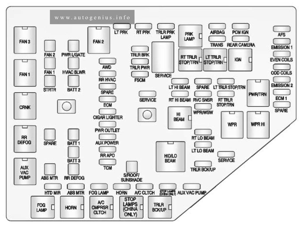
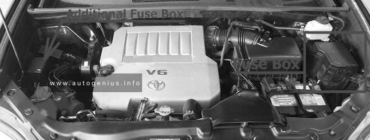
Engine compartment
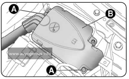
Fuse box location
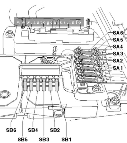
There are 2 fuse and relay boxes under the hood.
It is located in the engine compartment (left-side)
Fuse box diagram
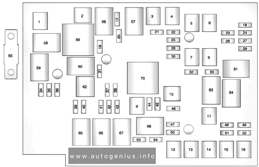
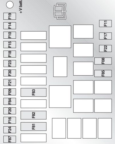
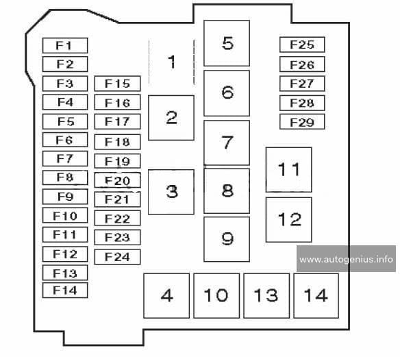
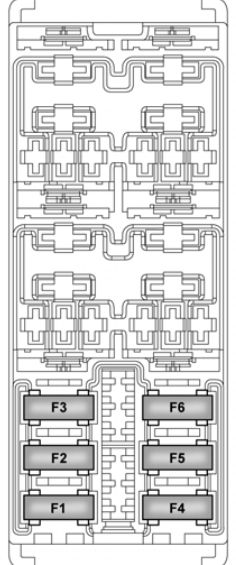
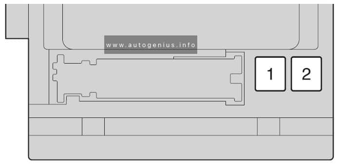
Type A (fuse block on the back of the cover)
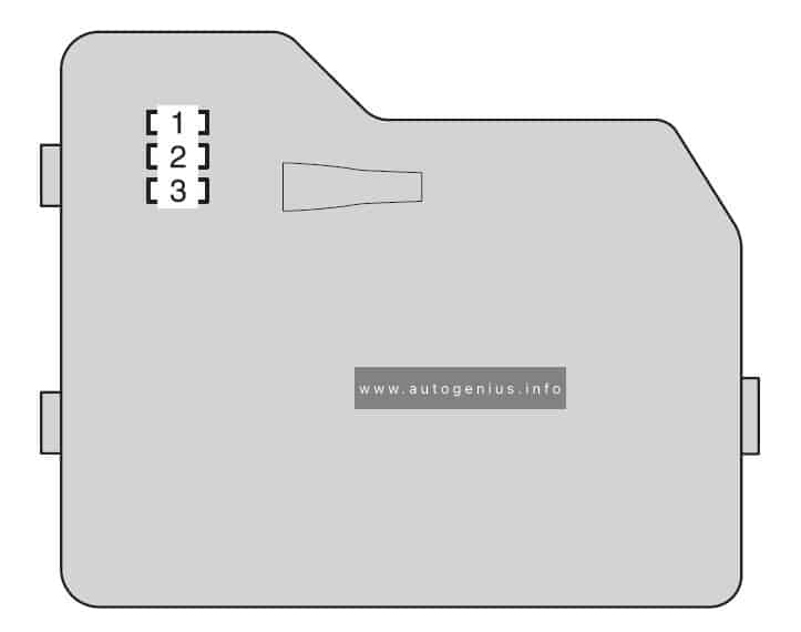
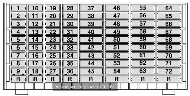
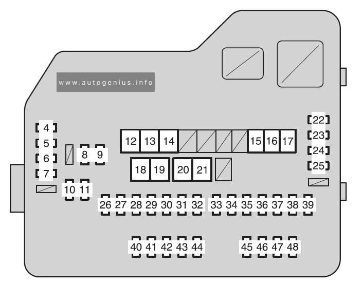
Type A (fuse block)
| Fuse | Ampere rating [A] | Circuit | |
| 1 | SPARE | 7,5 | Spare fuse |
| 2 | SPARE | 15 | Spare fuse |
| 3 | SPARE | 25 | Spare fuse |
| 4 | DEF RLY | 10 | Rear window defogger |
| 5 | MIR HTR | 20 | Outside rear view mirror defoggers |
| 6 | PWR OUTLET | 20 | Power outlet |
| 7 | DOOR NO.1 | 25 | Multiplex communication system |
| 8 | EFI NO.2 | 10 | Multiport fuel injection system/sequential multiport fuel injectionsystem |
| 9 | EFI NO.3 | 10 | Multiport fuel injection system/sequential multiport fuel injectionsystem |
| 10 | INJ NO.1 | 15 | Starting system |
| 11 | INJ NO.2 | 10 | Multiport fuel injection system/sequential multiport fuel injection system |
| 12 | HTR | 50 | Air conditioning system |
| 13 | VSC NO.1 | 50 | Enhanced vehicle stability control system |
| 14 | FAN MAIN | 50 | Electric cooling fan |
| 15 | VSC NO.2 | 30 | Enhanced vehicle stability control system |
| 16 | PTC NO.1 | 50 | Air conditioning system |
| 17 | PTC NO.2 | 30 | Air conditioning system |
| 18 | PTC NO.3 | 30 | Air conditioning system |
| 19 | RR CLR | 40 | Air conditioning system |
| 20 | RR DEF | 30 | Rear window defogger |
| 21 | PBD | 30 | Power back door |
| 22 | ALT | 140 | MIR HTR, PWR OUTLET, DOOR NO.1, HTR, RR DEF, FAN MAIN, VSC NO.1, PTC NO.1, RR CLR, PTC NO.2, PTC NO.3, VSC NO.2, PBD |
| 23 | EPS | 80 | Electric power steering |
| 24 | ST | 30 | Starting system |
| 25 | CRT | 10 | Rear seat entertainment system |
| 26 | RADIO NO.1 | 158 | Audio system |
| 27 | ECU-B NO.1 | 10 | Steering sensor, gauges and meters, clock, main body ECU, wireless remote control, smart key system, power back door, multiinformation display, front passenger occupant classification system |
| 28 | DOME | 10 | Vanity lights, personal lights, interior light, gauges and meters, engine switch light, door courtesy lights |
| 29 | TOWING | 30 | Trailer lights |
| 30 | STR LOCK | 20 | Steering lock system |
| 31 | EFI MAIN | 25 | Multiport fuel injection system/sequential multiport fuel injection system, EFI NO.2, EFI NO.3 |
| 32 | HAZ | 15 | Turn signal lights |
| 33 | IG2 | 25 | INJ NO.1, INJ NO.2, IGN, GAUGE NO.2 |
| 34 | AMP | 15 | Audio system |
| 35 | RR FOG | 7,5 | No circuit |
| 36 | DEICER | 15 | Windshield wiper de-icer |
| 37 | G/H | 10 | Glass hatch, multiplex communication system, outer foot lights |
| 38 | ALT-S | 7,5 | Charging system |
| 39 | AM2 | 7,5 | Multiplex communication system |
| 40 | H-LP LH HI | 15 | Left-hand headlight (high beam) |
| 41 | H-LP RH HI | 15 | Right-hand headlight (high beam) |
| 42 | H-LP LH LO | 15 | Left-hand headlight (low beam) |
| 43 | H-LP RH LO | 15 | Right-hand headlight (low beam) |
| 44 | HORN | 10 | Horn |
| 45 | EFI NO.1 | 10 | Multiport fuel injection system/sequential multiport fuel injection system, smart key system |
| 46 | ETCS | 10 | Multiport fuel injection system/sequential multiport fuel injection system, electronic throttle control system |
| 47 | A/F | 20 | Air fuel ratio sensor |
| 48 | S-HORN | 7,5 | Horn |
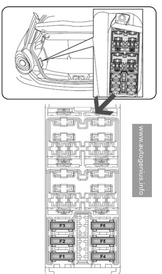
Type B (if equipped)
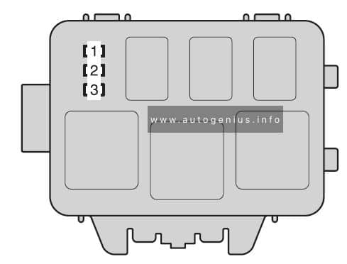
| Fuse | Ampere rating [A] | Circuit | |
| 1 | INV-W/P | 15 | No circuit |
| 2 | IGCT NO.2 | 7,5 | No circuit |
| 3 | A/C-D | 10 | No circuit |
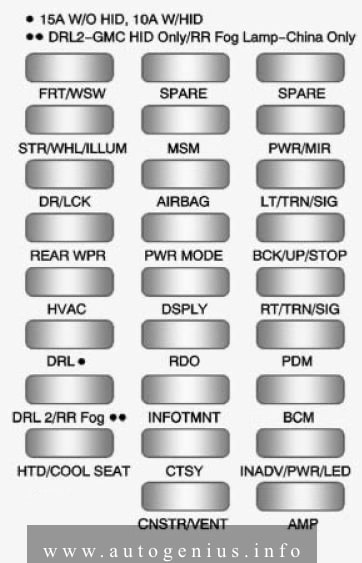
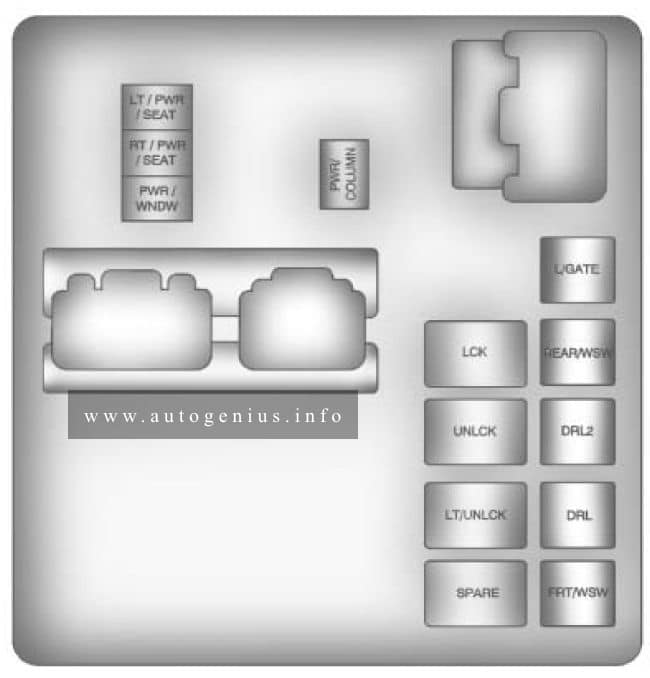
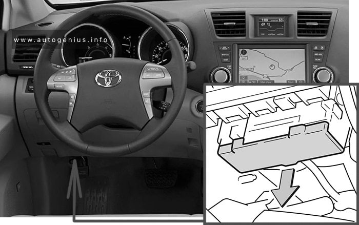
Passenger compartment
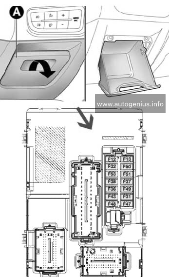
Fuse box location
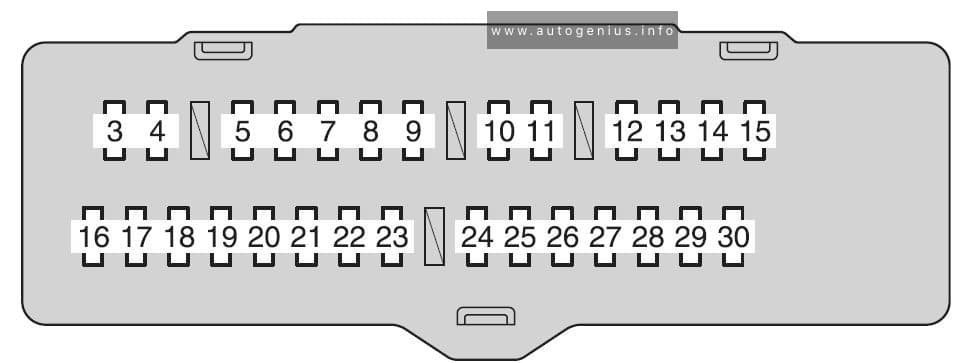
Fuse box diagram
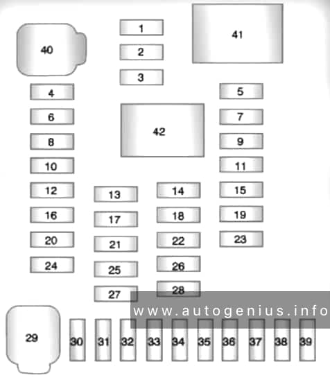
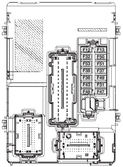
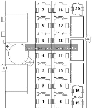
Front side of the fuse block
Fuse block
| Fuse | Ampere rating [A] | Circuit | |
| 1 | P/SEAT | 30 | Power seat |
| 2 | POWER | 30 | Power windows |
| 3 | RR DOOR RH | 25 | Power windows |
| 4 | RR DOOR LH | 25 | Power windows |
| 5 | FR FOG | 15 | Front fog lights |
| 6 | OBD | 7,5 | On-board diagnosis system |
| 7 | A/C W/PMP | 7,5 | No circuit |
| 8 | STOP | 10 | Enhanced vehicle stability control system, multiplex communication system, multiport fuel injection system/sequential multiport fuel injection system, shift lock system, stop lights |
| 9 | DOOR NO.2 | 25 | Power windows |
| 10 | AM1 | 7,5 | Starting system |
| 11 | P/SEAT (PS) | 30 | Power seat |
| 12 | A/C NO. 1 | 10 | Air conditioning system |
| 13 | FUEL OPN | 7,5 | No circuit |
| 14 | S/ROOF | 20 | Electric moon roof |
| 15 | TAIL | 15 | Parking lights, tail lights, license plate lights, front fog lights, trailer lights |
| 16 | PANEL | 7,5 | Glove box light, instrument panel lights, switch illumination |
| 17 | ECU IG NO.1 | 10 | Multiplex communication system, electric moon roof, electronically controlled automatic transmission system, power back door, seat heaters, tire pressure warning system, electronic power steering, anti-glare inside rear view mirror, shift lock system, tire pressure warning system |
| 18 | ECU IG NO.2 | 7,5 | Enhanced vehicle stability control system |
| 19 | A/C NO.2 | 10 | Air conditioning system |
| 20 | WASH | 20 | Windshield wipers and washer |
| 21 | S-HTR | 20 | Seat heaters |
| 22 | GAUGE NO.1 | 10 | Audio system, back-up lights, charging system, emergency flashers, traction control system, windshield wiper de-icer, air conditioning system, charging system, rear view monitor system, trailer lights, multiport fuel injection system/sequential multiport fuel injection system |
| 23 | FR WIP | 30 | Windshield wipers and washer |
| 24 | RR WIP | 15 | Rear window wiper and washer |
| 25 | IGN | 10 | Multiport fuel injection system/sequential multiport fuel injection system, steering lock system, antilock brake system, smart key system, SRS airbag system |
| 26 | GAUGE NO.2 | 7,5 | Gauges and meters, rear view monitor system |
| 27 | ECU-ACC | 7,5 | Outside rear view mirrors, shift lock system, smart key system, multiplex communication system |
| 28 | ACC SOCK NO.1 | 10 | Power outlet |
| 29 | ACC SOCK NO.2 | 20 | Power outlet |
| 30 | RADIO NO.2 | 7,5 | Audio system, clock, rear seat entertainment system, charging system, interior lights, personal lights |
WARNING: Terminal and harness assignments for individual connectors will vary depending on vehicle equipment level, model, and market.