Holden Captiva 5 (2011 – 2016) – fuse and relay box diagram
Year of production: 2011, 2012, 2013, 2014, 2015, 2016
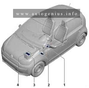
The Holden Captiva 5 (CG-II, facelifted), a compact crossover SUV, was manufactured between 2011 and 2016. This article provides fuse box diagrams for the 2011, 2012, 2013, 2014, 2015, and 2016 models. You’ll also find details about the location of the fuse panels within the vehicle and learn about the fuse and relay assignments (fuse layout).
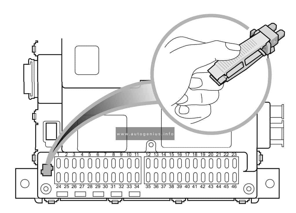
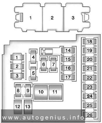
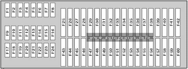
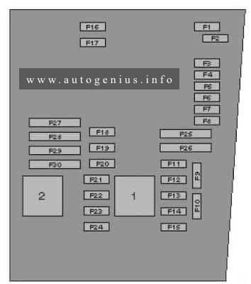
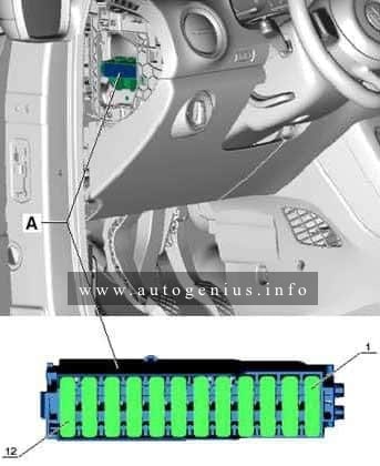
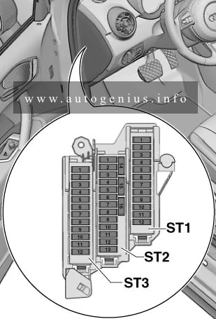
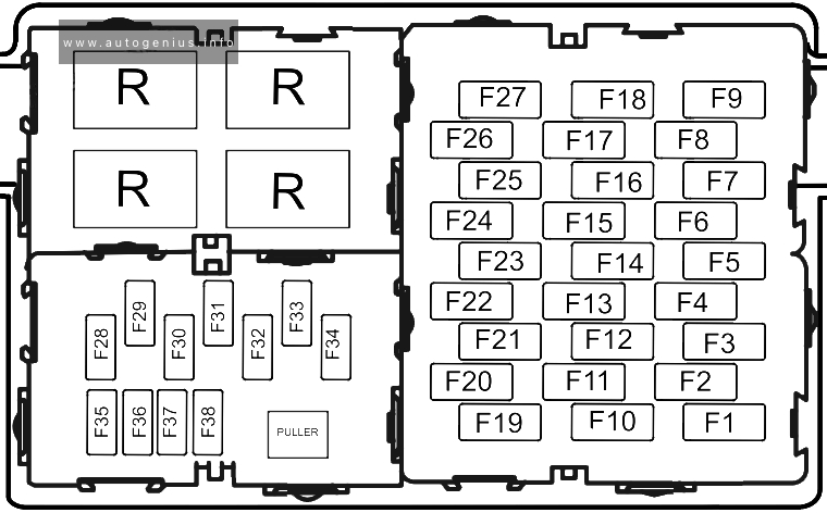
Passenger Compartment Fuse Box
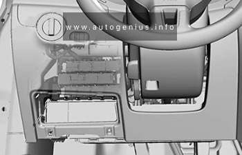
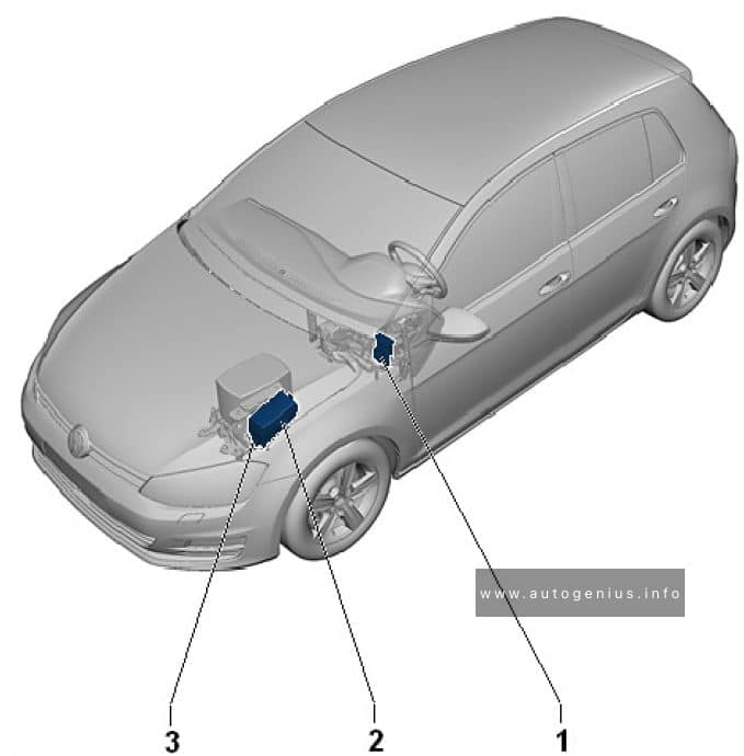
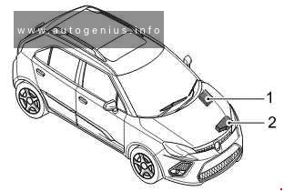
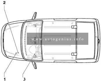
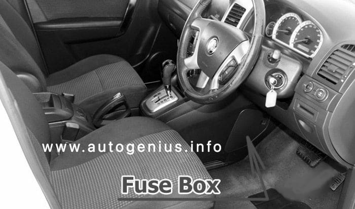
Fuse Box Location
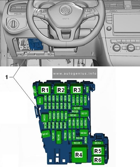
The fuses are located on the left-hand side of the driver’s side footwell. To open the fuse cover, pull the latch rearwards to disengage the cover.
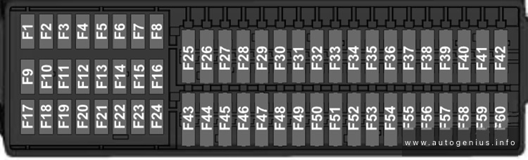
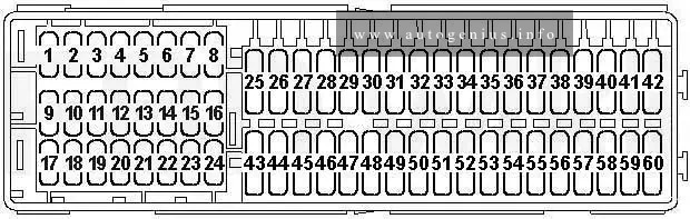
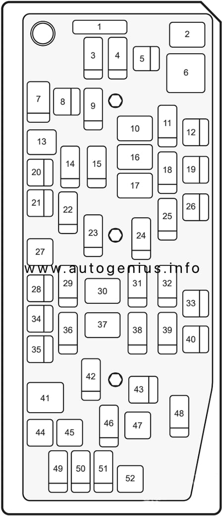
Fuse Box Diagram
Assignment of the fuses in the passenger compartment
| № | Amps | Description |
|---|---|---|
| 1 | 30A | DRVR PWR SEAT |
| 2 | 10A | S/ROOF FOLDING MIRROR |
| 3 | 20A | FSCM / VENT SOL |
| 4 | 15A | F/DOOR LOCK |
| 5 | 20A | DR/LCK |
| 6 | 20A | TRLR |
| 7 | 20A | APO JACK (CONSOLE) |
| 8 | 20A | HTD SEAT PWR / REAR A/C |
| 9 | 15A | BCM (PRK/TRN) |
| 10 | 30A | PASS PWR WNDW |
| 11 | ACC/RAP RELAY | |
| 12 | 20A | 2011-2013: S/ROOF BATT |
| 13 | 20A | CIGAR |
| 14 | 15A | BCM (STOP) |
| 15 | 15A | BCM (CTSY) |
| 16 | 20A | DRV PWR WNDW |
| 17 | CIGAR / APO JACK RELAY | |
| 18 | 20A | 2014-2016: S/ROOF BATT |
| 19 | 20A | APO JACK REAR CARGO |
| 20 | 15A | RUN/CRANK |
| 21 | SPARE | |
| 22 | 30A | AMP (audio system) |
| 23 | 15A | BCM (TRN SIG) |
| 24 | 15A | DRL |
| 25 | RUN RELAY | |
| 26 | 20A | FRT WSR |
| 27 | 10A | L/GATE |
| 28 | RUN/CRANK RELAY | |
| 29 | 20A | HEATING MAT SW |
| 30 | 10A | FSCM |
| 31 | 15A | AWD/VENT |
| 32 | 15A | 2015-2016: RR HEAT SEAT |
| 33 | 10A | RUN2 |
| 34 | 5A | ISRVM/RCM |
| 35 | 15A | RR FOG |
| 36 | 15A | BCM (DIMMER) |
| 37 | 15A | LOGISTIC MODE |
| 38 | 40A | HVAC BLWR |
| 39 | 10A | CLSTR |
| 40 | 10A | SDM (IGN 1) |
| 41 | 5A | PWR DIODE |
| 42 | 10A | 2011-2014: XBCM 2015-2016: BCM (VBATT) |
| 43 | 30A | TRLR BATT |
| 44 | 15A | RVS / HVAC / DLC |
| 45 | 2A | PWR / MODING |
| 46 | 10A | SSPS |
| 47 | 10A | XBCM |
| 48 | 20A | BCM (INT LIGHT) / TRLR FOG |
| 49 | 10A | IPC |
| 50 | 30A | 2015-2016: DC DC CONVERTER |
| 51 | 10A | SDM (BATT) |
| 52 | SPARE | |
| 53 | 2A | OSRVM |
| 54 | 10A | AUDIO / KEY CAPTURE |
| 55 | SPARE | |
| 56 | 2A | STR/WHL SW |
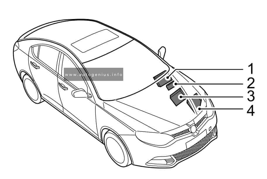
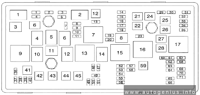
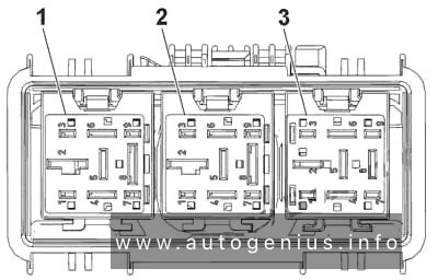
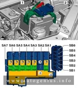
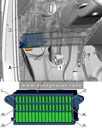
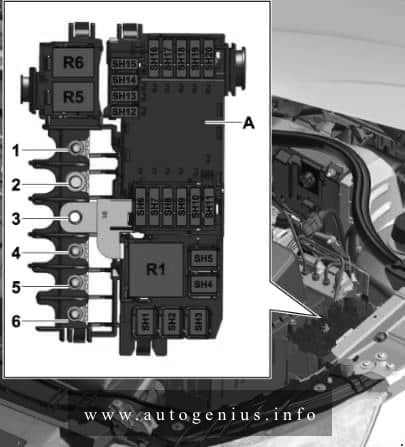
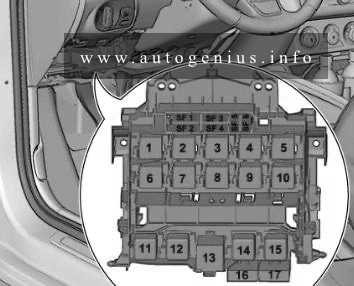
Engine Compartment Fuse Box
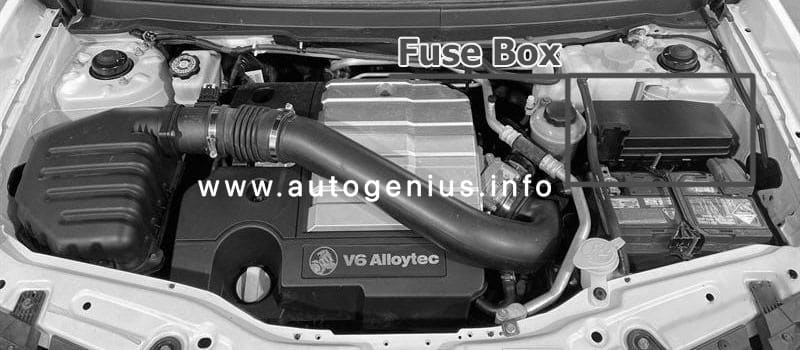
Fuse Box Location
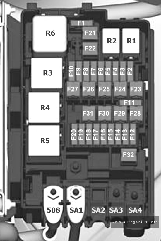
This fuse box is located toward the rear of the engine compartment next to the coolant reservoir, it contains circuit fuses, main fuses and relays. To remove the cover, press the catch on the side of the fuse box toward the engine and release the two tabs at the opposite side.
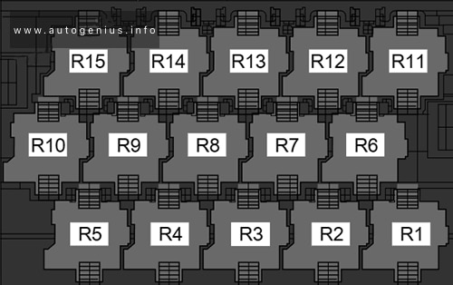
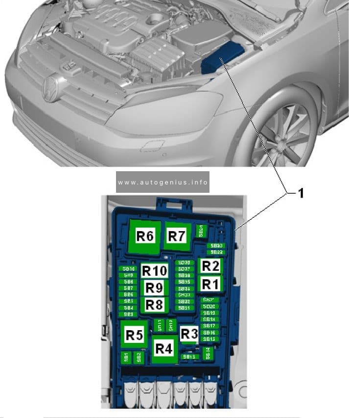
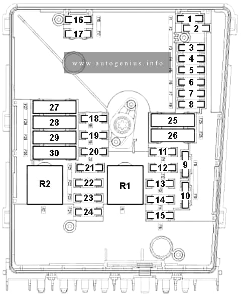
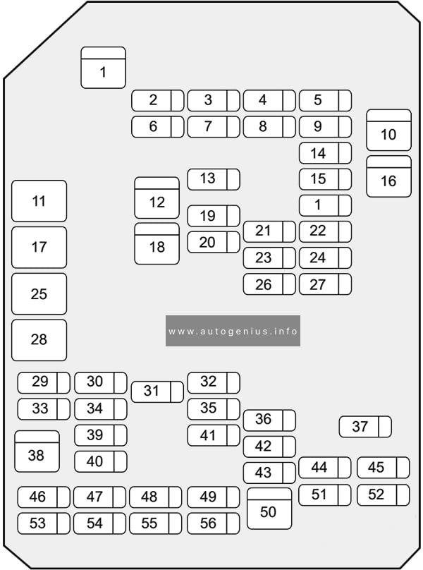
Fuse Box Diagram
Assignment of the fuses in the engine compartment
| № | Amps | Description |
|---|---|---|
| 1 | 80A | PWM FAN |
| 2 | 2011-2013: FAN1 RELAY | |
| 3 | 15A | 2011-2014: IGNITION COIL A 2015-2016: COIL A – OIL PUMP |
| 4 | 15A | IGNITION COIL B |
| 5 | 40A | 2011-2013: FAN1 |
| 6 | 2011-2013: FAN2 RELAY | |
| 7 | 15A | ECM |
| 8 | 40A | 2011-2013: FAN3 |
| 9 | 30A | ECM PWR TRN |
| 10 | PWR/TRN RELAY | |
| 11 | 15A | ENG SNSR |
| 12 | 20A | STRTR |
| 13 | 2011-2013: FAN3 RELAY 2014-2016: AUX PUMP RELAY |
|
| 14 | 15A | TCM |
| 15 | 15A | 2015-2016: AUX PUMP |
| 16 | STRTR RELAY | |
| 17 | FUEL/VAC PUMP RELAY | |
| 18 | 20A | ABS |
| 19 | 60A | BATT3 |
| 20 | SPARE | |
| 21 | 40A | EPB |
| 22 | 20A | STOP LAMP |
| 23 | 25A | FRT WPR |
| 24 | 10A | A/C |
| 25 | 10A | BCM |
| 26 | 20A | FUEL/VAC |
| 27 | STOP LAMP RELAY | |
| 28 | 60A | BATT2 |
| 29 | 10A | LO BEAM RH |
| 30 | WPR CNTRL RELAY | |
| 31 | 10A | PARK LP RH |
| 32 | 10A | PARK LP LH |
| 33 | SPARE | |
| 34 | 50A | ABS |
| 35 | 60A | BATT1 |
| 36 | 10A | LO BEAM LH |
| 37 | WPR SPD RELAY | |
| 38 | 20A | HDLP WASHER |
| 39 | 10A | TRLR PRK LAMP |
| 40 | 20A | REAR WIPER |
| 41 | REAR DEFOG RELAY | |
| 42 | 15A | HTD WASH / MIR |
| 43 | 30A | REAR DEFOG |
| 44 | LO BEAM RELAY | |
| 45 | HIGH BEAM RELAY | |
| 46 | 15A | FRTFOG |
| 47 | HDLP WSHR RELAY | |
| 48 | 10A | PRK LP RH/LIFT GATE |
| 49 | 15A | HORN |
| 50 | 10A | HI BEAM LH |
| 51 | 10A | HI BEAM RH |
| 52 | FRT FOG RELAY | |
| 53 | 10A | Spare |
| 54 | 15A | Spare |
| 55 | H/light washer relay |
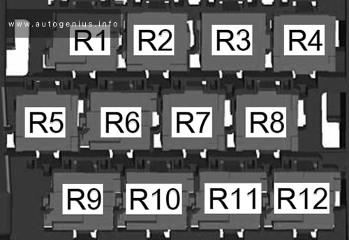
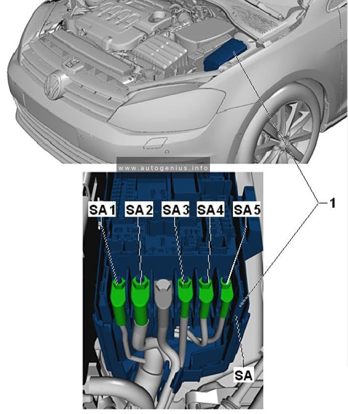
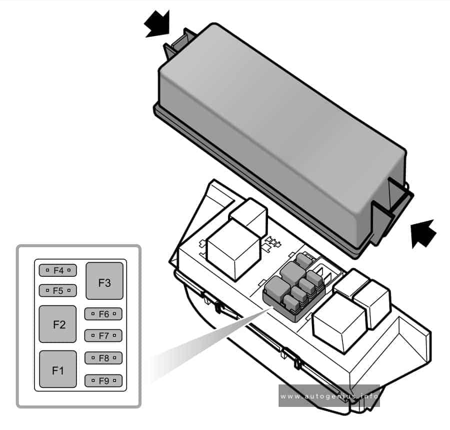
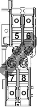
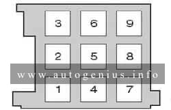
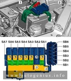
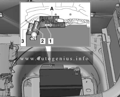
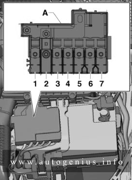
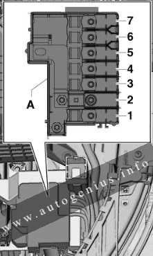
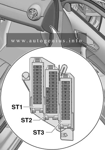
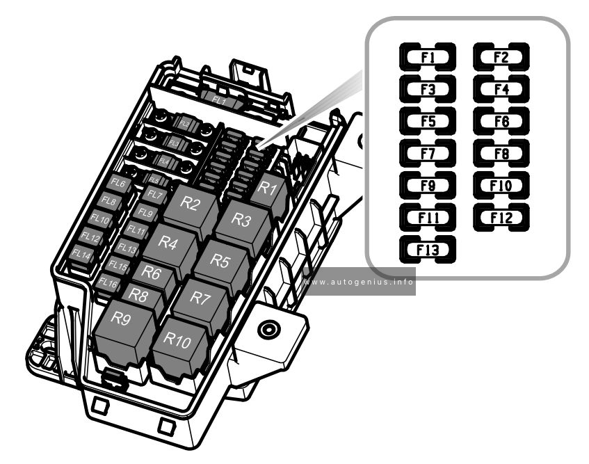
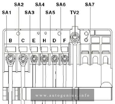
Diesel auxiliary fuse and relay block
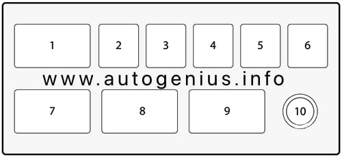
Assignment of the fuses in the auxiliary fuse block
| № | Amps | Description |
|---|---|---|
| 1 | Relay PTC 3 | |
| 2 | 40A | PTC 3 |
| 3 | 40A | PTC 2 |
| 4 | 40A | PTC 1 |
| 5 | 30A | F/F HTR |
| 6 | 60A | GPCU |
| 7 | Relay PTC 2 | |
| 8 | Relay PTC 1 | |
| 9 | Relay F/F HTR | |
| 10 | B+ |
WARNING: Terminal and harness assignments for individual connectors will vary depending on vehicle equipment level, model, and market.