Audi A1 (8X; 2010 – 2018) – fuse and relay box diagram
Year of production: 2010, 2011, 2012, 2013, 2014, 2015, 2016, 2017, 2018
In this article, we take a look at the first-generation Audi A1 (8X), manufactured from 2010 to 2018. You will find fuse box diagrams for Audi A1 models from 2010 through 2018, learn where the fuse panels are located inside the vehicle, and discover the function of each fuse and relay (fuse layout).
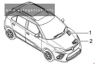
Location
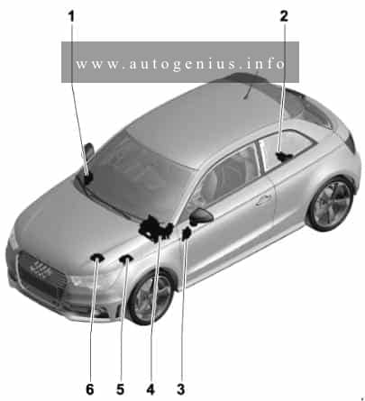
- Fuse holder D -SD-
- Fuse holder A -SA-
- Fuse holder C -SC-
- Relay/fuse holder F -SF-
- Fuse holder B -SB-, Fuse holder H -SH-
- Fuse holder B -SB-
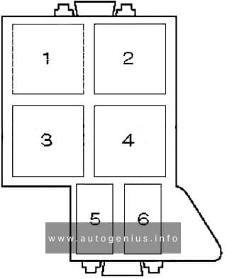
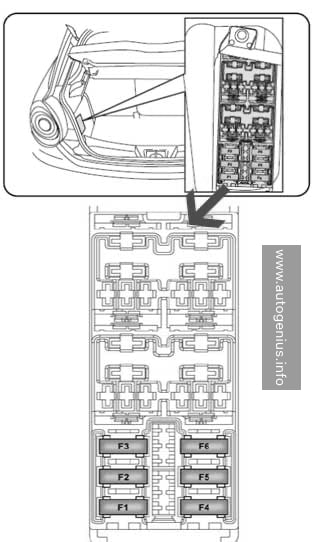
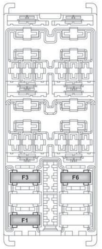
Luggage compartment (Fuse holder A -SA-)
At battery positive terminal (for models with battery in luggage compartment only).
Fuse box diagram
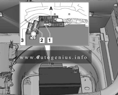
Assignment of the fuses in the luggage compartment (fuse holder A)
| No. | A | Function/component |
| 1 | – | Vacant |
| 2 | 110 | Onboard supply Engine component supply |
| 3 | – | Vacant |
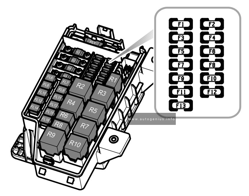
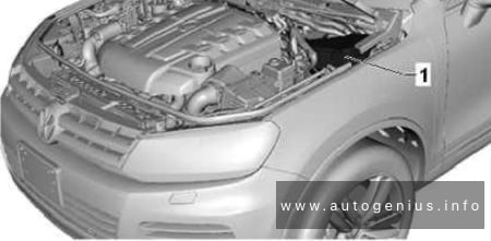
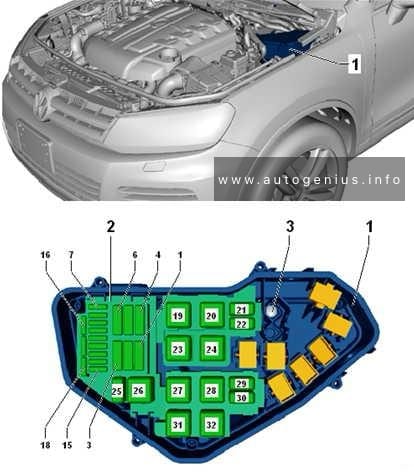
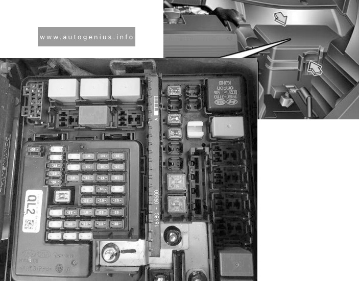
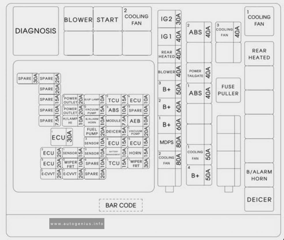
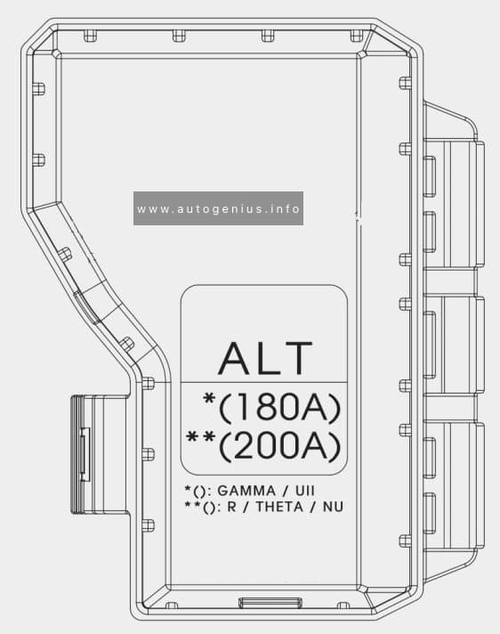
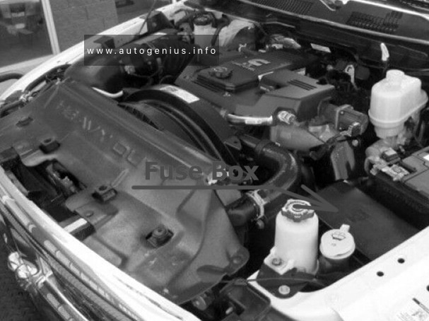
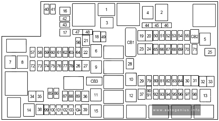
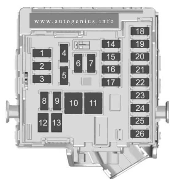
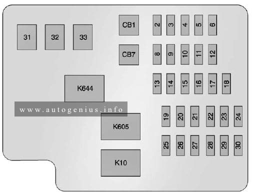
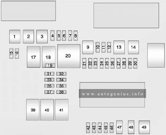
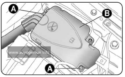
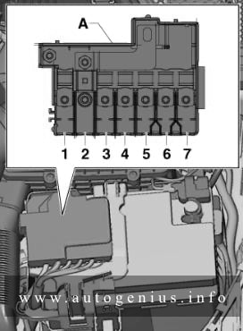
Engine comparmtnet (Fuse holder B -SB-)
Fuse box diagram (for models with battery in engine compartment)
Fuse box diagram (for models with battery in luggage compartment)
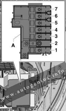
Assignment of the fuses in the engine compartment
| No. | A | Function/component |
| 1 | 175 | Alternator -C- |
| 2 | 40 | Low heat output relay -J359- Heater element for auxiliary air heater -Z35- |
| 3 | 110 1) | Onboard supply1) Engine component supply1) |
| 4 | 80 | Power steering control unit -J500- |
| 5 | 50 2) 40 3) |
Radiator fan thermal switch -F18- Radiator fan control unit -J293- |
| 6 | 50 | Automatic glow period control unit -J179- |
| 7 | 60 | High heat output relay -J360- Battery monitor control unit -J3671) Auxiliary heater element -Z35- |
| 1) for models with battery in engine compartment only 2) no longer fitted, phased out (model year 2011) 3) phased-in modification (model year 2011) |
||
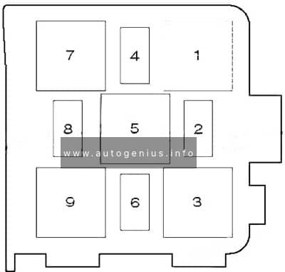
Engine comparment
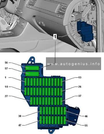
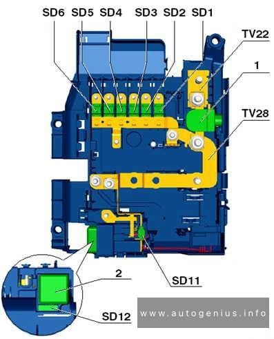
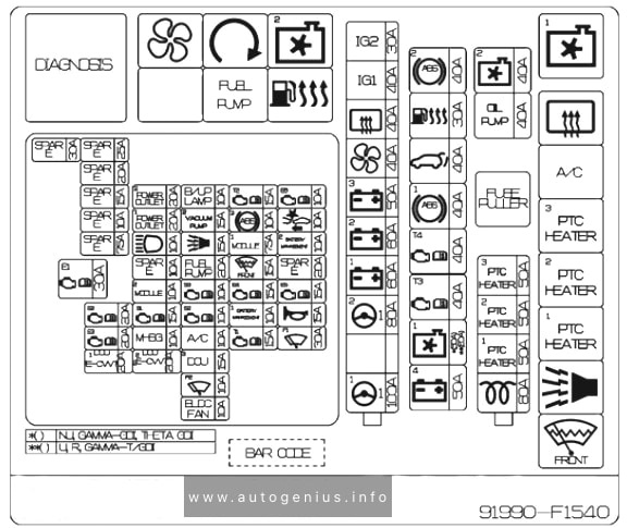
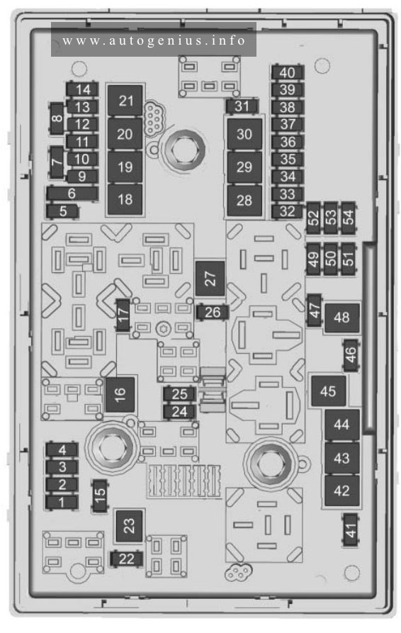
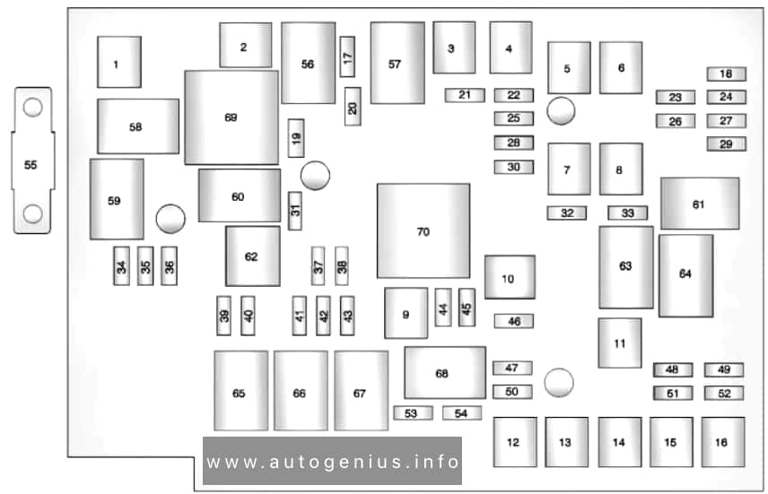
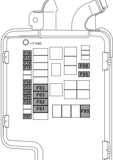
Fuses in electronics box in fuse holder B -SB-/ Fuse holder H -SH-
Fuse box diagram
In electronics box, in left engine compartment.
For S1 version models only, from January 2014, For models from November 2014 only.
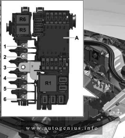
Fuses in the electronics box
| No. | A | Function/component |
| 1 | 110 4)
5 5) |
Onboard supply4) Engine component supply4) Radiator fan control unit -J293-5) Radiator fan -V7-5) |
| 2 | 250 | Alternator -C- Voltage regulator -C1- |
| 3 | – | Battery + |
| 4 | 80 | Power steering control unit -J500- |
| 5 | 50 6) | Automatic glow period control unit -J179-6) Glow plug 1 -Q10- Glow plug 2 -Q11- Glow plug 3 -Q12- Glow plug 4 -Q13- |
| 6 | 50 7)
– 8) |
Radiator fan control unit -J293-7) Radiator fan -V7-7) – |
| 7 | 125 | Onboard supply8) Engine component supply8) |
| 4) for models with battery in engine compartment only, up to October 2014 5) for models from November 2014 only 6) for models with diesel engine only, from November 2014 7) for models up to October 2014 8) for models with battery in engine compartment only, from November 2014 9) Fuse 5 on fuse holder B -SB5- bridged, (see note) |
||
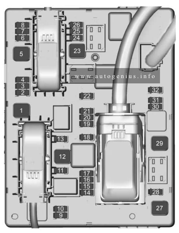
Fuses in electronics box in fuse holder H -SH-
Fuses in the electronics box
| No. | A | Function/component |
| 1 | 40 | Heater element for auxiliary air heater -Z35-, stage 1 |
| 2 | 30 | Radiator fan control unit -J293- Radiator fan -V7- |
| 3 | – | Vacant |
| 4 | 40 | Heater element for auxiliary air heater -Z35-, stage 2 |
| 5 | 40 | Heater element for auxiliary air heater -Z35-, stage 3 |
| 6 | 30 | Mechatronic unit for dual clutch gearbox -J743- |
| 7 | 7.5 | Engine control unit -J623- |
| 8 | 20 | Wiper motor switch-over relay 1 -J368- Wiper motor switch-over relay 2 -J369- |
| 9 | 5 | Battery monitor control unit -J367- |
| 10 | 10 | Suppression filter -C24- |
| 11 | – | Vacant |
| 12 | 10 12) 15 13)10)11) |
Lambda probe heater -Z19- Lambda probe 1 heater after catalytic converter -Z29- |
| 13 | 5 | Brake light switch -F- Clutch position sender -G476- |
| 14 | 5 13) 10 10)11)12) |
Thermal switch for air conditioning system shut-off -F163- Fuel metering valve -N290- Oil pressure regulation valve -N428- Cylinder head coolant valve -N489- Coolant circulation pump -V50- Circulation pump -V55- Charge air cooling pump -V188- Auxiliary heating pump -V488- |
| 15 | 5 | Onboard supply control unit -J519-, T52c/34 Engine control unit -J623-, T91/67;T94/… Voltage stabiliser -J532-, T12aa/4 |
| 16 | 30 | Starter motor -B- |
| 17 | 15 12)13) 30 10)11) |
Engine control unit -J623- |
| 18 | 5 10)11) 10 12)13) |
Oil level and oil temperature sender -G266- Fuel pump relay -J17- Radiator fan control unit -J293- Low heat output relay -J359- High heat output relay -J360- Charge pressure control solenoid valve -N75- Recirculation valve for turbocharger -N249- Intake manifold flap valve -N316- Oil pressure regulation valve -N428- Cooling oil valve -N471- |
| 19 | 7.5 10) 10 11)13) 20 12) |
Engine component current supply relay -J757- Fuel pressure regulating valve -N276- Fuel metering valve -N290- Injector 2 for cylinder 1 -N532- Injector 2 for cylinder 2 -N533- Injector 2 for cylinder 3 -N534- Injector 2 for cylinder 4 -N535- Actuator 1 for camshaft adjustment -F366- Actuator 2 for camshaft adjustment -F367- Actuator 3 for camshaft adjustment -F368- Actuator 4 for camshaft adjustment -F369- Actuator 5 for camshaft adjustment -F370- Actuator 6 for camshaft adjustment -F371- Actuator 7 for camshaft adjustment -F372- Actuator 8 for camshaft adjustment -F373- Vacuum pump for brakes -V192- |
| 20 | 5 10)11) 10 13) 20 12) |
Automatic glow period control unit -J179- Exhaust flap control unit -J883- Crankcase breather heater element -N79- Activated charcoal filter solenoid valve 1 -N80- Camshaft control valve 1 -N205- Exhaust camshaft control valve 1 -N318- Continued coolant circulation pump -V51- Sender 1 for secondary air pressure -G609- Sender 2 for secondary air pressure -G610- |
| 10) for models with 1.4 l diesel engine only 11) for models with 1.6 l diesel engine only 12) for models with 1.0 l/1.4 l petrol engine only 13) for models with 1.8 l/2.0 l petrol engine only |
||
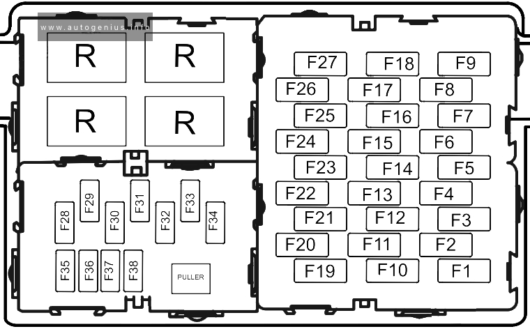
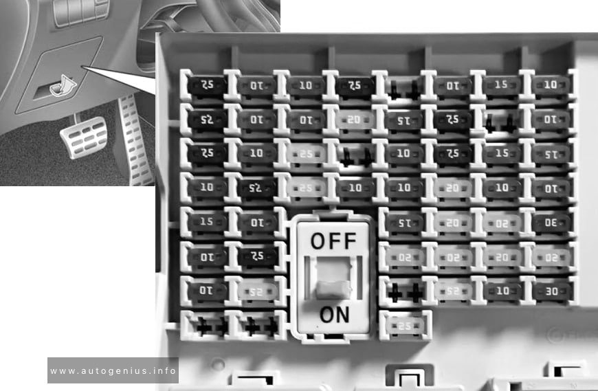
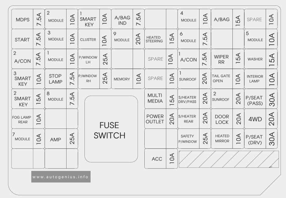
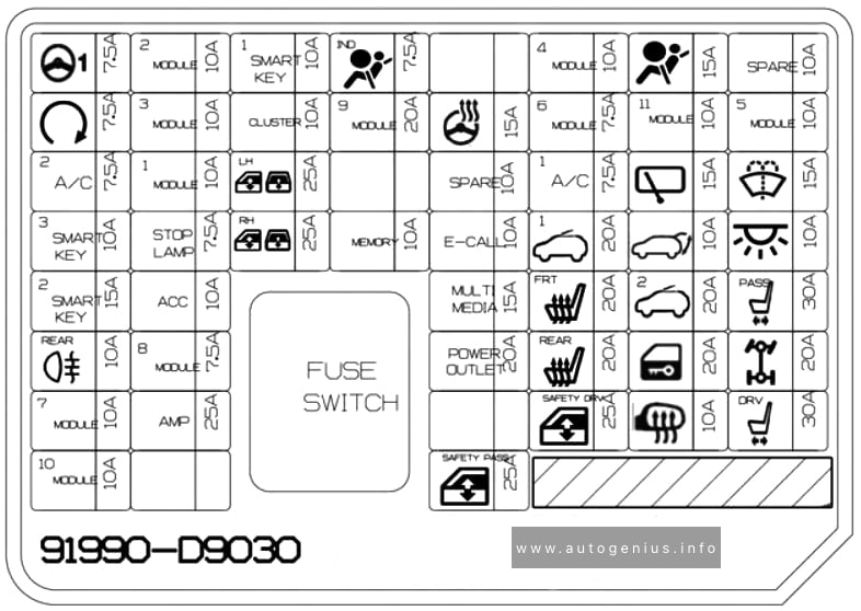
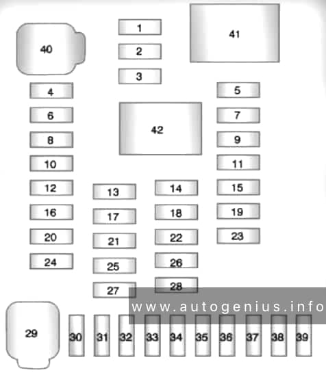
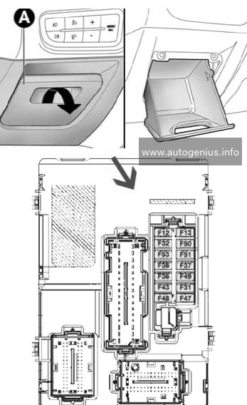
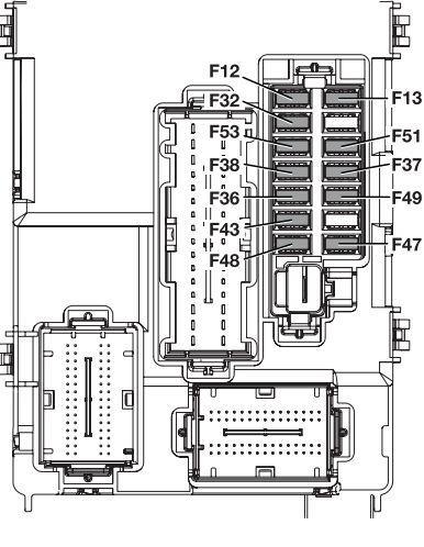
Passenger compartment
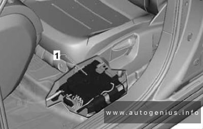
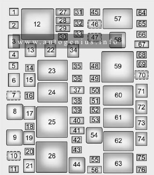
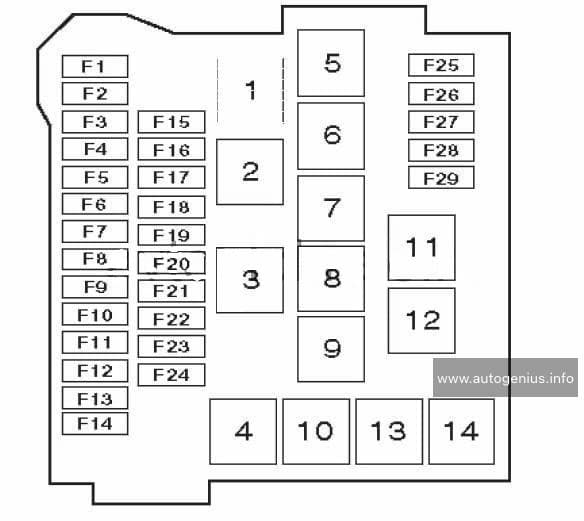
Fuse box diagram (Fuse holder C -SC-)
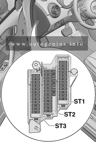
Fuse Box in the driver’s side of the instrument panel
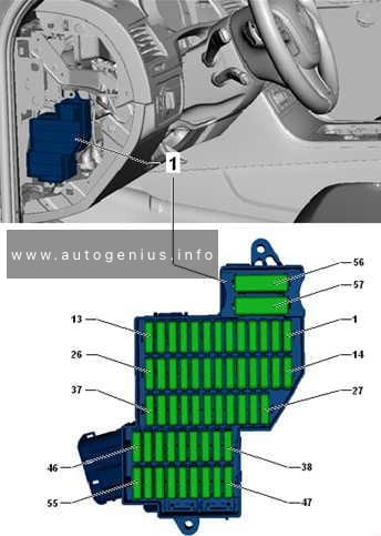
Fuse box diagram (Fuse holder D -SD-)
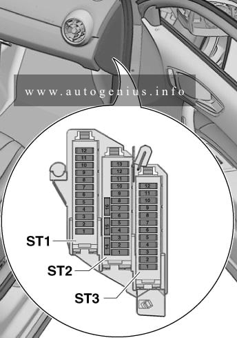
Fuse Box in the passenger’s side of the instrument panel
| No. | A | Function/component |
| Black | ||
| 1 | 7.5 | ESL control unit -J764- |
| 2 | 20 | Trailer detector control unit -J345- |
| 3 | 20 | Trailer detector control unit -J345- |
| 4 | 30 7.5 |
Mechatronic unit for dual clutch gearbox -J743-, up to October 2014 Electronically controlled damping control unit -J250-, from January 2014 |
| 5 | 30 | Headlight washer system relay -J39- Headlight washer system pump -V11- |
| 6 | 5 | Interface control unit for vehicle location system -J843- |
| 7 | 7.5 | Entry and start authorisation control unit -J518- |
| 8 | 15 | Mechatronic unit for dual clutch gearbox -J743-, up to October 2014 |
| 9 | 20 | Sliding sunroof motor -V1- |
| 10 | 7.5 | Selector lever sensors control unit -J587- |
| 11 | 15 35) | Engine component current supply relay -J757-, up to October 2014 Fuel pressure regulating valve -N276- , up to October 2014 |
| 12 | – | Vacant |
| Brown | ||
| 1 | 5 | Reversing light switch -F4- Selector lever sensors control unit -J587- Mechatronic unit for dual clutch gearbox -J743- |
| 2 | 10 | High-pressure sender -G65- Oil level and oil temperature sender -G266- Air conditioning system control unit -J301- Relay for power sockets -J807- Automatic anti-dazzle interior mirror -Y7- 16-pin connector -T16-, diagnosis connection |
| 3 | 5 | Data bus diagnostic interface -J533- |
| 4 | 5 | Heater control unit -J65- Control unit for structure-borne sound -J869- |
| 5 | 7.5 | Light switch -E1- Starter relay 1 -J906- Voltage stabiliser -J532- Starter relay 2 -J907- Relay for automatic anti-dazzle interior mirror -J910- Front left headlight -MX1- Front right headlight -MX2- |
| 6 | 5 | Light switch -E1- |
| 7 | 5 | ABS control unit -J104-, up to October 2014 Voltage stabiliser 2 -J570-, up to October 2014 Electronically controlled damping control unit -J250-, from January 2014 |
| 8 | 5 | Heated driver seat regulator -E94- Heated front passenger seat regulator -E95- Hazard warning lights button -E229- Heated rear window button -E230- TCS and ESP button -E256- Parking aid button -E266- Tyre pressure monitor display button -E492- Start/Stop operation button -E693- Trailer detector control unit -J345- Left washer jet heater element -Z20- Right washer jet heater element -Z21- |
| 9 | 5 | Power steering control unit -J500- |
| 10 | 5 36) 7.5 37) |
Air mass meter -G70- Fuel pump control unit -J538- Crankcase breather heater element -N79- |
| 11 | 5 | Airbag control unit -J234- Front passenger airbag deactivated warning lamp -K145- |
| 12 | 5 | Parking aid control unit -J446- |
| 13 | 5 | Control unit for headlight range control -J431- |
| 14 | 30 | Seat heating control unit -J882- |
| 15 | 15 | Rear window wiper motor -V12- |
| 16 | 5 | Engine control unit -J623- Air mass meter -G70- |
| Red | ||
| 1 | – | Vacant |
| 2 | – | Vacant |
| 3 | 10 | All-wheel drive control unit -J492- , gradual phase-out |
| 4 | – | Vacant |
| 5 | – | Vacant |
| 6 | – | Vacant |
| 7 | – | Vacant |
| 8 | – | Vacant |
| 9 | – | Vacant |
| 10 | 5 10 |
Special vehicle control unit -J608- |
| 11 | – | Vacant |
| 12 | – | Vacant |
| 35) for models with 2.0 l petrol engine only 36) for models with petrol engine only 37) for models with diesel engine only |
||
Fuse box diagram (relay/fuse holder F -SF-)
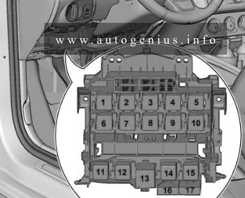
Fuse/Relay panel under the steering wheel
| No. | A | Function/component |
| 1 | 40 | Voltage stabiliser -J532- |
| 2 | 50 | Supply fuse carrier 1 -ST1- in fuse holder D -SD- |
| 3 | 40 | Terminal 15 voltage supply relay -J329- |
| 4 | 40 | ABS control unit -J104- |
| 5 | 5 | Voltage stabiliser 2 -J570-, gradual phase-out |
| 6 | 5 | Onboard supply control unit -J519- Voltage stabiliser -J532- Voltage stabiliser 2 -J570-, gradual phase-out Engine control unit -J623- |
| 16 | 10 | Brake light switch -F- (from November 2011, up to October 2014) Clutch position sender -G476- (from November 2011, up to November 2014) |
| 17 | 5 | Lambda probe heater -Z19- (from November 2011, up to October 2014) Lambda probe 1 heater after catalytic converter -Z29- (from November 2011, up to November 2014) |
WARNING: Terminal and harness assignments for individual connectors will vary depending on vehicle equipment level, model, and market.