Alfa Romeo Giulietta (2013 – 2020) – fuse box diagram
Year of production: 2013, 2014, 2015, 2016, 2017, 2018, 2019, 2020
Alfa Romeo Giulietta is a compact hatchback produced since 2010. It was created as the older model of the Alfa Romeo MiTo. Our material will help owners of Alfa Romeo Giulietta 2011, 2012, 2013, 2014, 2015, 2016, 2017, 2018, 2019, 2020 (During this time, the model underwent a facelift several times.) in finding and replacing fuses and relays. We will also show fuse box diagrams and locations. NOte the cigarette lighter fuse.
There are 3 main fuse boxes in this model. One is in the engine compartment, the second is in the passenger compartment under the dashboard, and the third is in the luggage compartment.
Type 1
For cars manufactured before 2016
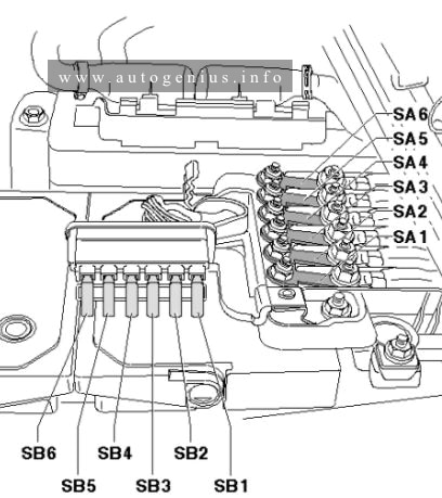
Engine compartment fuse box
This fuse box is located near the battery.
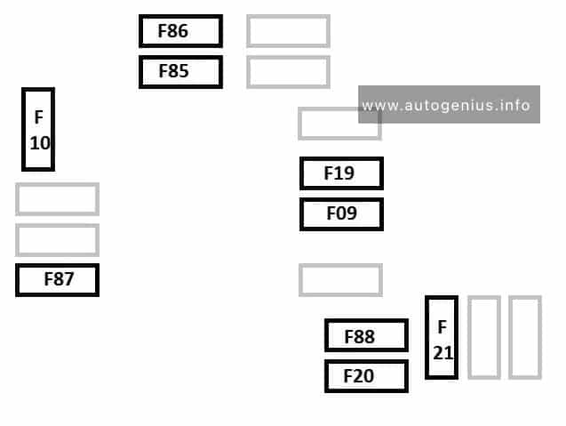
Alfa Romeo Giulietta FL – fuse box – engine compartment
| Device protected | Fuse | Ampere rating [A] |
| Headlamp washer pump power supply | F09 | 30 |
| Horn | F10 | 15 |
| AC compressor | F19 | 7,5 |
| Heated rear window | F20 | 30 |
| Fuel pump | F21 | 15 |
| Cigar lighter/power socket | F85 | 15 |
| 12 V boot power socket | F86 | 15 |
| IBS Battery charge status sensor for Start&Stop system | F87 | 5 |
| External mirror defrosters | F88 | 7,5 |
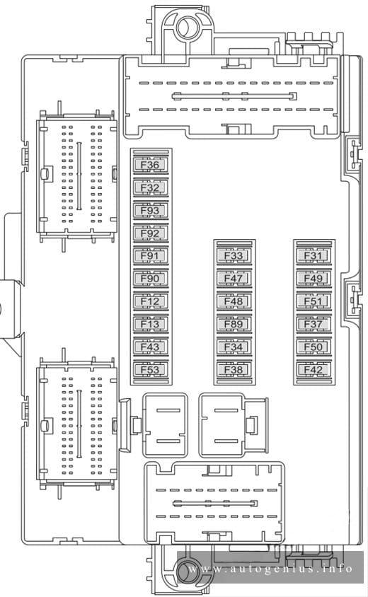
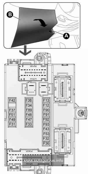
Passenger compartment
Fuse box is located under the dashboard. The bolt attachment points for access to the unit are shown in the picture.
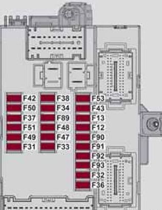
Alfa Romeo Giulietta – fuse box diagram – dashboard
| Device protected | Fuse | Ampere rating [A] |
| Right main beam headlight | F91 | 7,5 |
| Left main beam headlight | F90 | 7,5 |
| Right dipped beam headlight (versions with halogen headlights) | F12 | 7,5 |
| Left dipped beam headlight (versions with halogen headlights) | F13 | 7,5 |
| Right dipped beam headlight (versions with Bi-Xenon headlights) | F12 | 15 |
| Left dipped beam headlight (versions with Bi-Xenon headlights) | F13 | 15 |
| Right fog light | F93 | 7,5 |
| Left fog light | F92 | 7,5 |
| Luggage compartment courtesy light/Sun visor courtesy light/Glove compartment courtesy light/Front and rear roof lights | F32 | 10 |
| Various devices | F31 | 5 |
| Rear electric window (left side) | F33 | 20 |
| Rear electric window (right side) | F34 | 20 |
| +30 | F36 | 10 |
| Various devices | F37 | 7,5 |
| Central locking | F38 | 20 |
| Body Computer supply | F42 | 5 |
| Two-way windscreen washer pump | F43 | 20 |
| Front electric window (driver side) | F47 | 20 |
| Front electric window (passenger side) | F48 | 20 |
| Various devices | F49 | 5 |
| Various devices | F50 | 7,5 |
| Various devices | F51 | 5 |
| +30 | F53 | 7,5 |
Luggage compartment
This box is located under the casing on the left side.
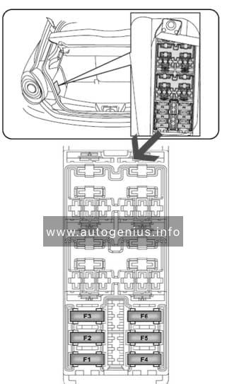
| Device protected | Fuse | Ampere rating [A] |
| Left front seat movement | F1 | 15 |
| Right front seat movement | F2 | 15 |
| Electric sun roof | F3 | 15 |
| Lumbar adjustment devices | F4 | 15 |
| Front seat heating | F5 | 15 |
| BOSE amplifier + Subwoofer | F6 | 20 |
Type 2
For cars manufactured from 2016
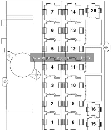
Passenger compartment fuse box
This fuse box is located near the battery.
Fuse box diagram
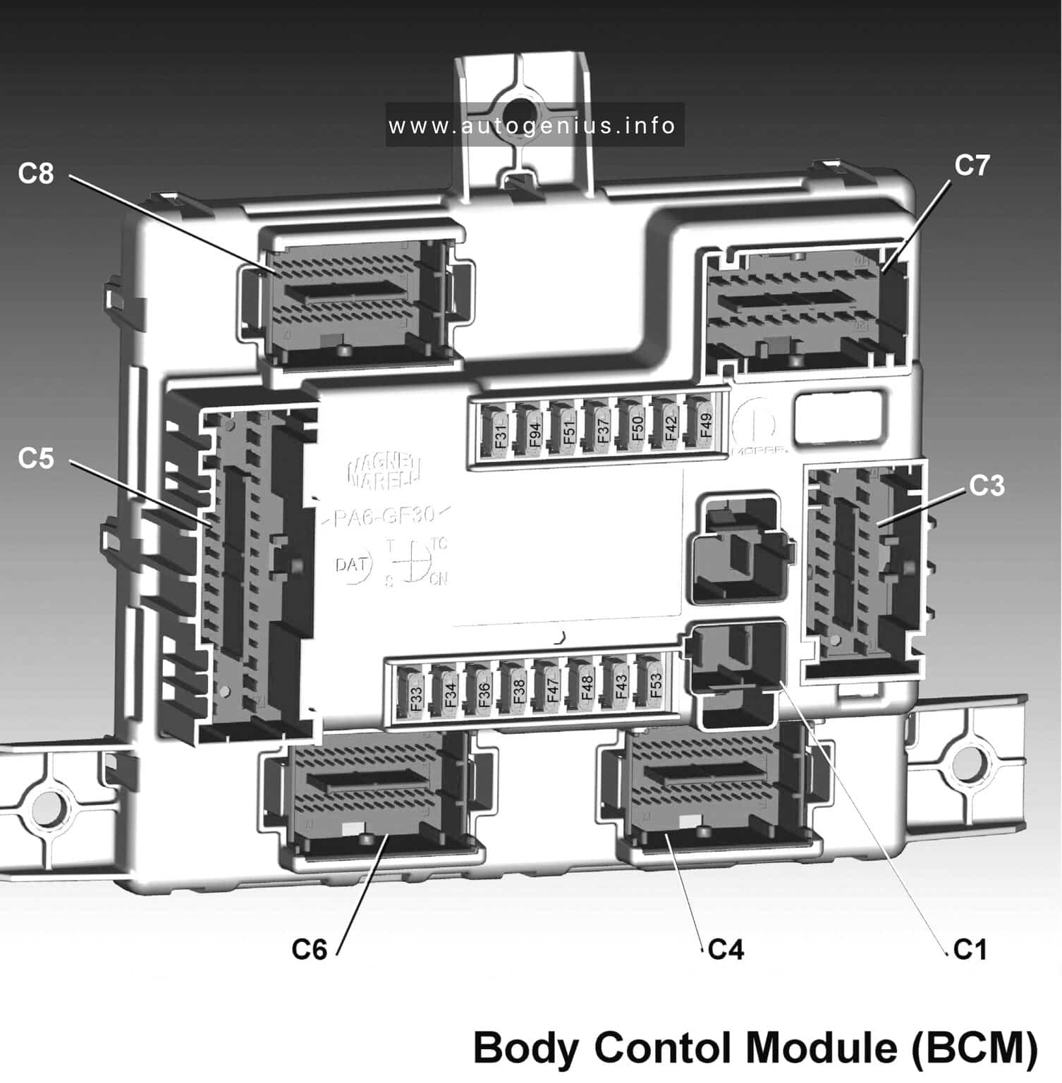
| Fuse | Device protected | Ampere rating [A] |
| F31 | Int/A power supply (key-on) | 7,5 |
| F33 | Electric window motor driver’s side | 25 |
| F34 | Electric window motor passenger’s side | 25 |
| F36 | Direct power supply from battery +30 | 15 |
| F37 | Int power supply (key-on) | 10 |
| F38 | Central door locking | 20 |
| F42 | Int key-on power supply (possible use for ECU 6.1) | 7,5 |
| F43 | Windscreen washer pump | 20 |
| F47 | Rear electric window motor left side | 25 |
| F48 | Rear electric window motor left side | 25 |
| F49 | Int key-on power supply | 7,5 |
| F50 | Int key-on power supply (possible use for ECU 6.1) | 7,5 |
| F51 | N/A | 7,5 |
| F53 | Direct power supply from battery +30 | 7,5 |
| F94 | Power sockets | 15 |
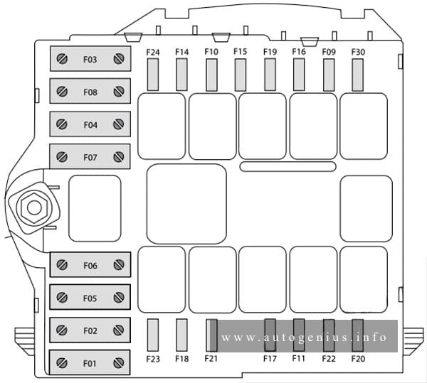
Engine compartment fuse box
This fuse box is located near the battery.
Fuse box diagram
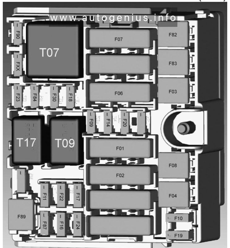
| Fuse | Device protected | Ampere rating [A] |
| F01 | MK C1 ABS Modul | 70 |
| F02 | Glow plug control unit | 60 |
| F03 | For BCM relay T38 | 30 |
| F04 | ABS module fans | 40 |
| F06 | Splitter | 30 |
| F07 | Main relay (2.9V6 master) | 50 |
| F08 | N/A | 40 |
| F09 | +30 ECM (2.02GME – 2.9V6 Salve); +30 P86 main relay | 7,5 |
| F10 | Horn | 15 |
| F11 | Engine secondary loads (2.02GME) | 15 |
| Engine primary loads (2.9V6 slave) | ||
| F14 | Blow-by heater (2.2JTDM) | 15 |
| F16 | KL15 fro ECM, ATX, DCTM | 5 |
| F17 | ECM (2.2JTDM) | 15 |
| F18 | +30 ATC (if equipped) | |
| F19 | A/C Compressor | 10 |
| F20 | N/A | 7,5 |
| F22 | ECM engine primary loads (slave 2.9V6 and 2.2JTDM) | 20 |
| F23 | Additional electric water pump (2.9V6/2.2JTDM) | 20 |
| F24 | For JTDM engine secondary loads | 15 |
| F30 | KL30 ATX Lever | 10 |
| F82 | Windscreen washer | 20 |
| F83 | AWD* | 25 |
| F84 | +30 ECM 2.9 V6 Master | 7,5 |
| F87 | Gerarbox oil cooling circuit electric pump (2.9 V6) | 15 |
| F89 | Headlight washer pump | 30 |
| F90 | Left splitter actuator (slave) | 20 |
| FXX | Right splitter actuator (master) | 20 |
| Relay | ||
| T07 | Main relay (2.9V6 master) | |
| T09 | Main relay (JTDM, GIMe, 2.9V6 slave) | |
| T17 | Headlight washer pump | |
Relay box diagram
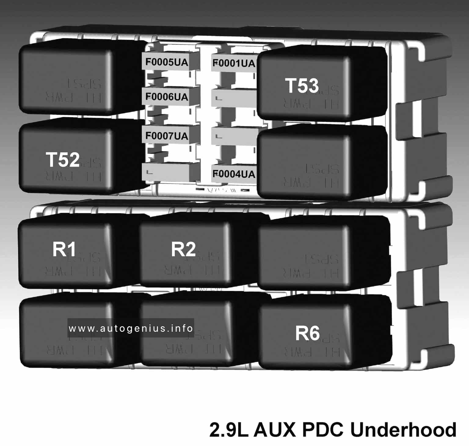
| No. | A | Description |
| F1 | 10 | Splitter actuators |
| F4 | 5 | Secondary master |
| F5 | 25 | Secondary loads (slave) |
| F7 | 20 | Primary loads ECM master |
| R1 | Horns | |
| R2 | A/C Clutch | |
| R6 | Starter solenoid 1 | |
| T52 | Water pump | |
| T53 | Blow by control | |
Luggage compartment
Fuse and relay box diagram
Power distribution Center (PDC)
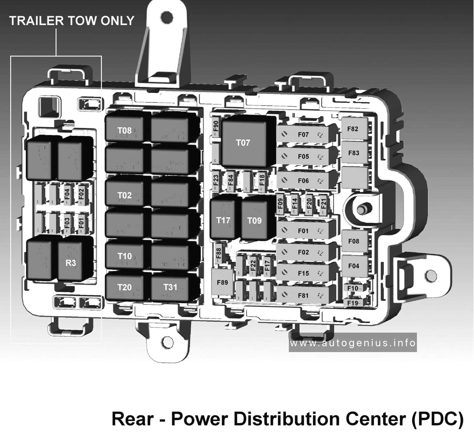
| Fuse | Device protected | Ampere rating [A] |
| F01 | TTM | 40 |
| F01 | TTM (Trailer tow) | 15 |
| F02 | ECU Chassis domain control | 40 |
| F02 | ECU Chassis domain control (trailer tow) | 15 |
| F03 | N/A (trailer tow) | 10 |
| F04 | Heated filter | 40 |
| F04 | Heated filter (trailer tow) | 10 |
| F05 | HVAC fan | 40 |
| F06 | TV/M/LSDM (power) | 30 |
| F07 | PTC3 | 60 |
| F08 | HI-FI | 30 |
| F09 | Passenger’s electric seat movement | 20 |
| F10 | ANC (Sound system) | 10/15 |
| F14 | KL30 ATX | 15 |
| F15 | PTC1 | 40 |
| F17 | KL15/A USB REACHER | 7,5 |
| F18 | Driver’s electric seat movemnet | 10 |
| F19 | KL30 ECU chassis domain control | 7,5 |
| F20 | Power supply for driver’s electric seat + driver and passenger heaters | 25 |
| F21 | I-DRIVE/USB/AUX port | 10 |
| F22 | KL15/A 12V power socket | 20 |
| F23 | Sunroof (BCM) | 20 |
| F81 | PTC2 | 60 |
| F82 | BCM for key relay | 20 |
| F83 | Fuel pump (2.9V/2.2 JTDM) | 30 |
| F84 | TVM/LSDL (electronic) | 5 |
| F88 | Heated mirrors/heated windscreen washer nozzles | 7,5 |
| F89 | Rear window defroster | 30 |
| F30 | IBS | 5 |
| Relays | ||
| R3 | Trailer tow | |
| T02 | Active damping | |
| T07 | PTC 3 | |
| T08 | Power seat | |
| T09 | Power outlet | |
| T10 | Fuel pump | |
| T17 | Rear defroster | |
| T20 | Blower motor | |
| T31 | Filter heater | |
Fuse box diagram
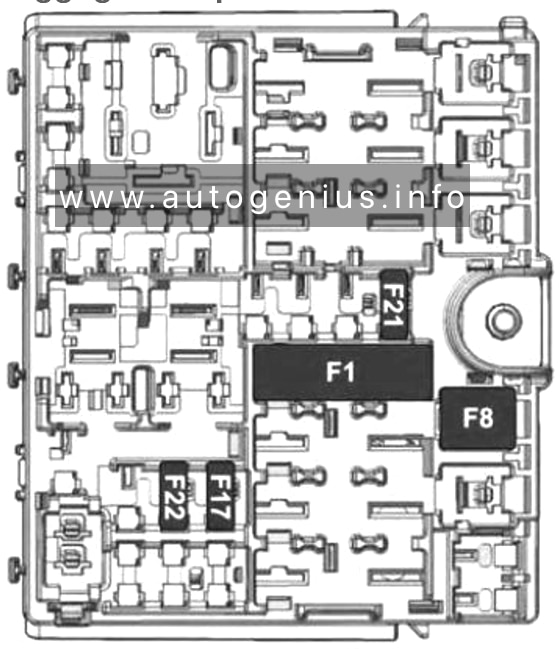
| No. | A | Description |
| F1 | 40 | Tow hook module (TTM) |
| F8 | 30 | Hi-Fi system |
| F17 | 7,5 | KL15/a USB Recharge (C070) |
| F21 | 10 | I-Drive / USB / AUX port |
| F22 | 20 | KL15/a 12V Power outlet (R053) |
WARNING: Terminal and harness assignments for individual connectors will vary depending on vehicle equipment level, model, and market.