Audi Q8 (2023 – 2025) – fuse and relay box diagram
This article covers to the Audi Q8 (B3), produced from 2018 to present. It includes fuse box diagrams for the 2023, 2024 and 2025 models, provides details on the location of the fuse panels inside the vehicle, and explains the function and layout of each fuse.
Year of production: 2023, 2024, 2025
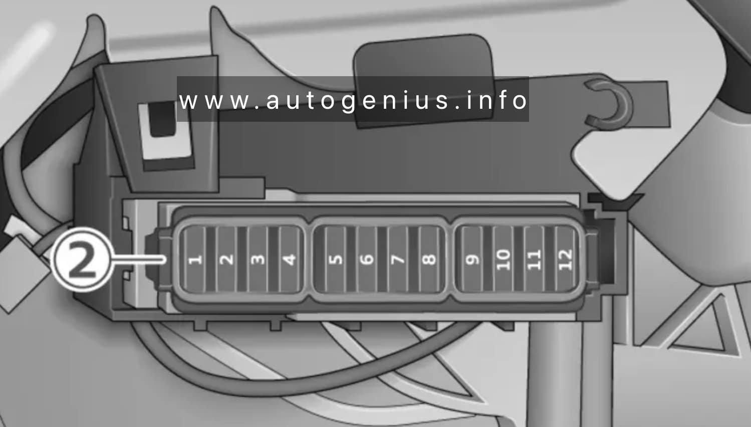
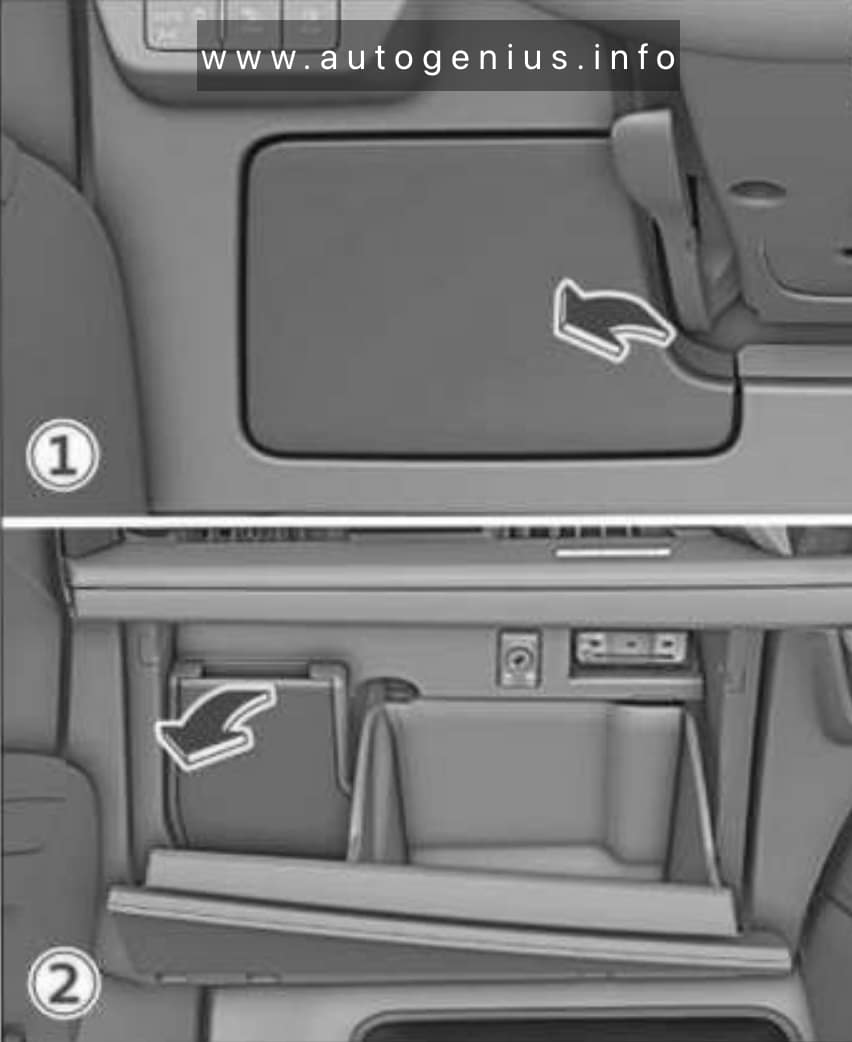
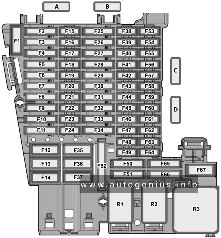
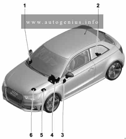
Passenger compartment
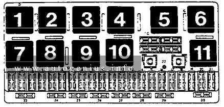
Fuse box diagram (dashboard)
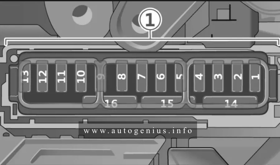
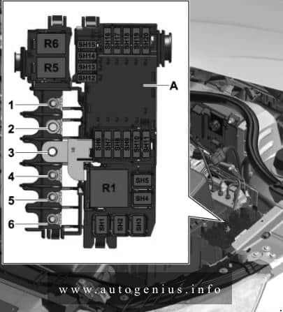
Assignment of the relays in the passenger compartment (dashboard)
| № | Description |
|---|---|
| 1 | – |
| 2 | Audi phone box, external aerial |
| 3 | Air conditioner, perfume function |
| 4 | Head-up display |
| 5 | USB ports with charging function |
| 7 | Steering column lock |
| 8 | Upper/lower display |
| 9 | Instrument cluster |
| 10 | DVD drive |
| 11 | Light switches, switch panels |
| 12 | Steering column electronics |
| 13 | Volume control |
| 14 | MMI infotainment control unit |
| 15 | Steering column adjustment |
| 16 | Heating for steering wheel |
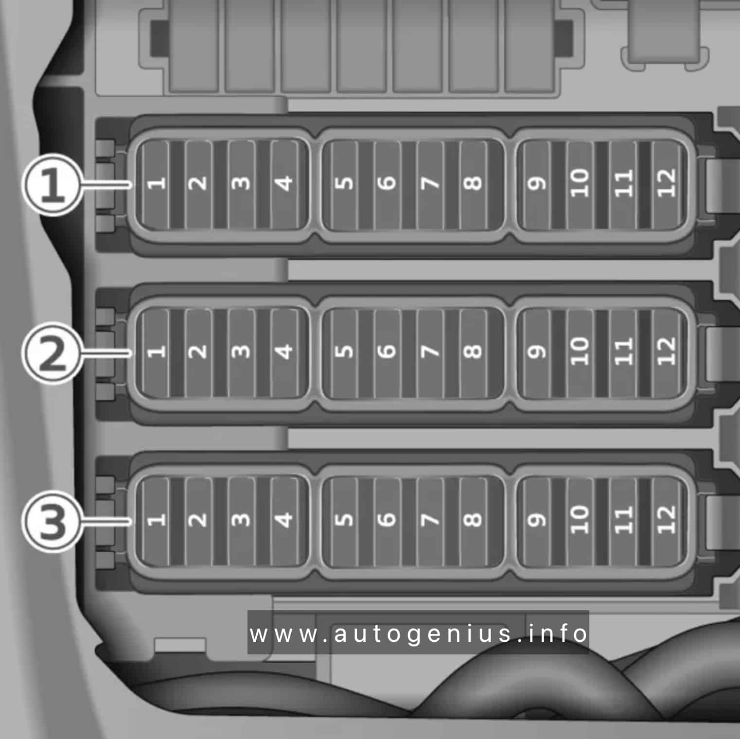
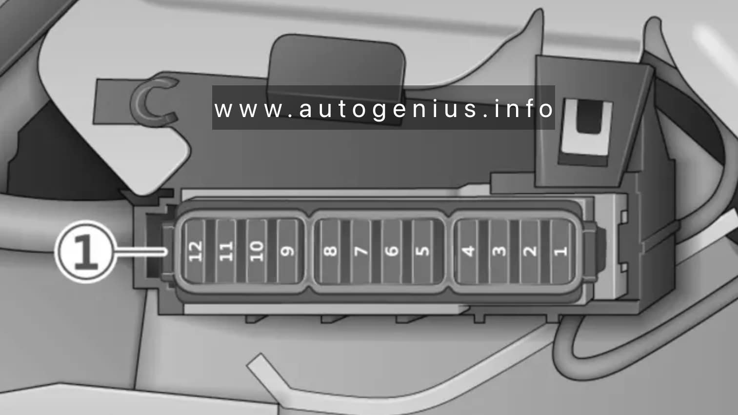
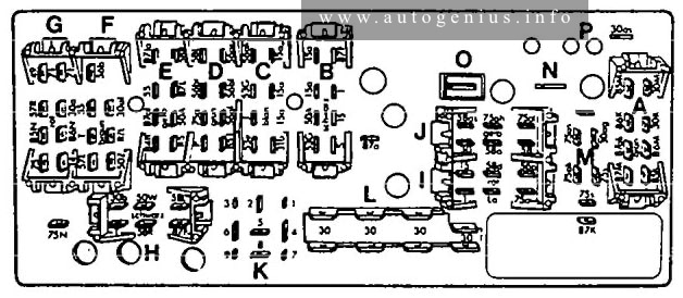
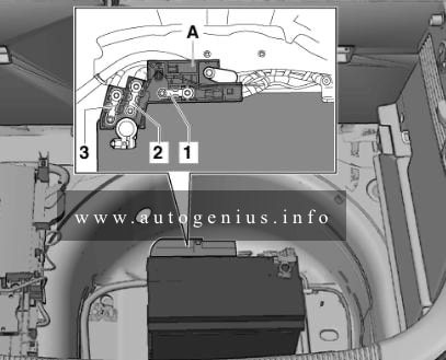
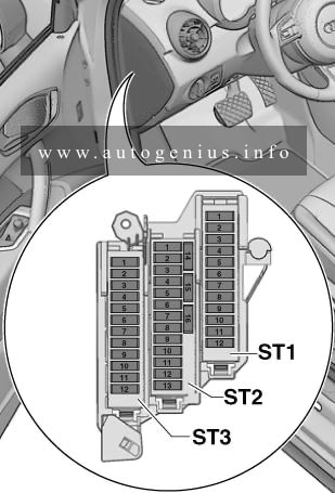
Fuse box diagram (Footwell)
Version 1
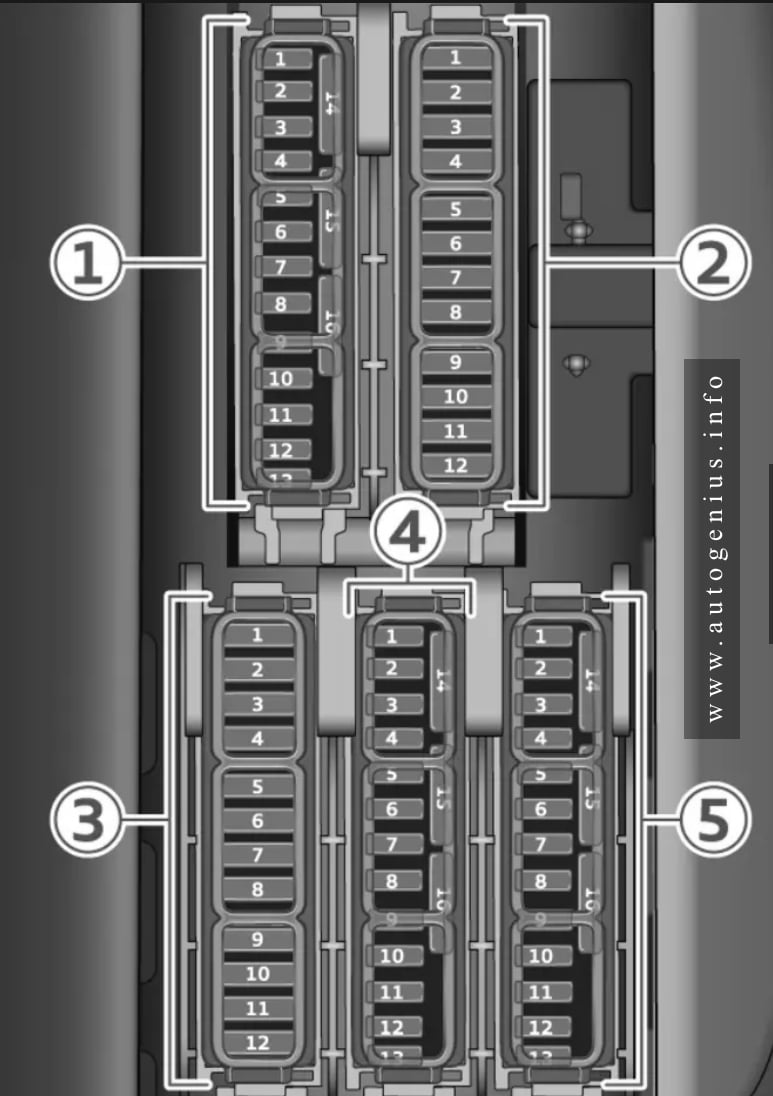
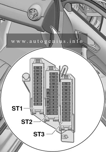
Version 2 (RHD)
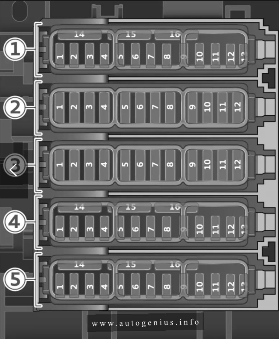
Assignment of the relays in the passenger compartment (footwell)
| № | Description |
|---|---|
| Fuse panel 1 (brown) | |
| 1 | Catalytic converter heater, camshaft adjuster |
| 2 | Air mass meter, Lambda probes |
| 3 | Engine heating, injectors, exhaust flaps |
| 4 | Heating water pump, exhaust flaps, NOx sensor, particulate sensor, biodiesel sensor |
| 5 | Brake light sensor |
| 6 | Engine valves |
| 7 | Lambda probes, air mass meter |
| 8 | High-pressure pump, engine mountings |
| 9 | Engine components, engine relays |
| 10 | Oil pressure sensor, oil temperature sensor |
| 11 | 48 V coolant pump, 48 V starter alternator, 12 V starter alternator |
| 12 | Engine valves |
| 13 | Engine cooling |
| 14 | Drive system control unit |
| 15 | Oxygen sensors |
| 16 | Fuel pump |
| Fuse panel 2 (red) | |
| 1 | Ignition coils |
| 4 | Electric compressor |
| 5 | Engine mountings |
| 6 | Windscreen washer system control unit |
| 7 | Dash panel |
| 8 | Air conditioner blowers |
| 9 | Control unit for driver assist systems |
| 10 | Emergency call and communication control unit |
| 11 | Power unit start, clutch for electric drive system |
| Fuse panel 3 (black) | |
| 1 | Seat heating (front) |
| 2 | Wipers |
| 3 | Headlight electronics (left) |
| 4 | Panorama sun roof |
| 5 | Door control unit (front left) |
| 6 | Sockets |
| 7 | Door control unit, rear right |
| 9 | Headlight electronics (right) |
| 10 | Control unit for windscreen/headlight washer system |
| 11 | Door control unit, rear left |
| 12 | Auxiliary heating, exterior sound generator |
| Fuse panel 4 (brown) | |
| 1 | Seat ventilation, seat electronics, interior mirror, A/C control console (rear), diagnostic connection, traffic information aerial (TMC) |
| 2 | Control unit for vehicle electrical system, diagnostic interface |
| 3 | Engine sound control unit |
| 4 | Gear oil cooling valve |
| 5 | Power unit start, electric drive system |
| 7 | Active accelerator |
| 8 | Night vision assist, active roll stabilisation |
| 9 | Adaptive cruise assist, front radar sensors |
| 10 | External sound generator |
| 11 | Intersection assist, driver assist systems |
| 13 | Left headlight |
| 15 | USB connection |
| Fuse panel 5 (red) | |
| 1 | Anti-theft alarm system |
| 2 | Drive system control unit |
| 3 | Seat electronics (front), lumbar support |
| 4 | Selector lever for automatic gearbox |
| 5 | Horn |
| 6 | Parking brake |
| 7 | Diagnostic interface |
| 8 | Roof electronics control unit |
| 9 | Electronic toll collection system (ETC) |
| 10 | Airbag control unit |
| 11 | Electronic stabilisation control (ESC), anti-lock brake system (ABS) |
| 12 | Diagnostic connection, light sensor/rain sensor |
| 13 | Air conditioner |
| 14 | Door control unit, front right |
| 15 | Air conditioner compressor |
| 16 | Brake system pressure accumulator |
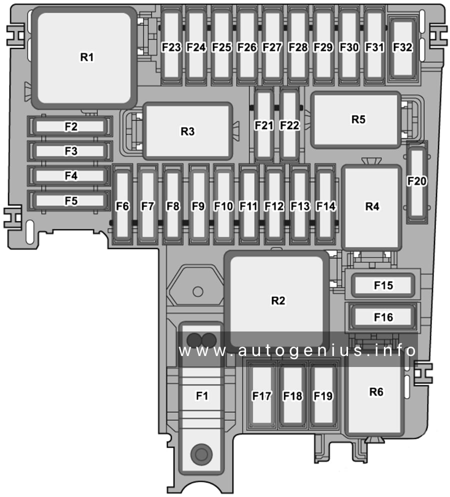
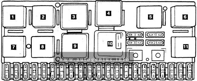
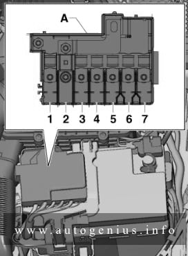
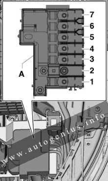
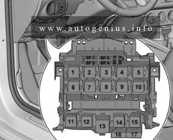
Luggage compartment
Fuse box diagram
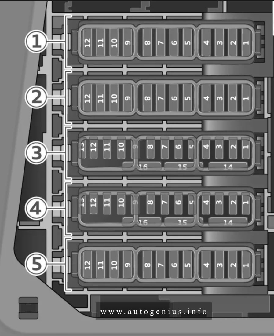
Assignment of the relays in the luggage compartment
| № | Description |
|---|---|
| Fuse panel 1 (black) | |
| 1 | High-voltage heater, thermal management |
| 5 | Air suspension/suspension control |
| 6 | Automatic gearbox control unit |
| 7 | Seat heating (rear), A/C control console (rear) |
| 9 | Central locking system, rear light (left-side) |
| 10 | Front belt tensioner (driver’s side) |
| 11 | Central locking for boot lid, fuel tank flap, luggage compartment cover |
| 12 | Boot lid control unit |
| Fuse panel 2 (red) | |
| 1 | Air conditioner blowers (rear) |
| 2 | Sound system |
| 3 | Emission control, engine sound control unit |
| 4 | A/C control console (rear) |
| 5 | Towing bracket (right lights) |
| 6 | Towing bracket swivel motor |
| 7 | Towing bracket release |
| 8 | Towing bracket (left lights) |
| 9 | Electrical socket for towing bracket |
| 10 | Four-wheel sport differential |
| 11 | Emission control |
| 12 | Rear belt tensioner (driver’s side) |
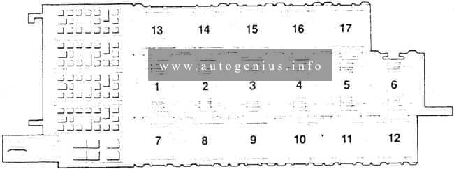
| Fuse panel 3 (brown) | |
| 1 | Control unit for driver assist systems |
| 3 | Lumbar support (right-side) |
| 4 | Side assist |
| 6 | Tyre pressure loss indicator |
| 7 | External aerial |
| 8 | Remote control receiver (auxiliary heater), fuel tank module |
| 10 | TV tuner, control unit for data exchange and telematics |
| 11 | Control unit for convenience access and start authorisation |
| 12 | Garage door opener |
| 13 | Reversing camera, surround view cameras |
| 14 | Convenience system control unit, rear light (right-side) |
| 15 | Rear belt tensioner (passenger’s side) |
| 16 | Front belt tensioner (passenger’s side) |
| Fuse panel 4 (red) | |
| 1 | Active roll stabilisation |
| 2 | Emergency cut-out connection for high-voltage battery |
| 3 | Coolant pump for high-voltage battery |
| 4 | Power electronics control unit |
| 5 | Brake servo |
| 6 | Voltage transformer |
| 7 | Engine start |
| 8 | Air conditioner compressor |
| 9 | Control unit for additional battery |
| 10 | High-voltage battery |
| 11 | Charging system |
| 12 | Remote control receiver for auxiliary heater/air conditioning |
| 14 | Thermal management, coolant pumps |
| 15 | Thermal management control unit |
| Fuse panel 5 (brown) | |
| 7 | Seat heating (front) |
| 9 | Emission control |
| 10 | Seat heating (rear), A/C control console (rear) |
| 12 | Emission control |
WARNING: Terminal and harness assignments for individual connectors will vary depending on vehicle equipment level, model, and market.