| № |
Designation in Wiring Diagram |
A |
Component |
Terminal |
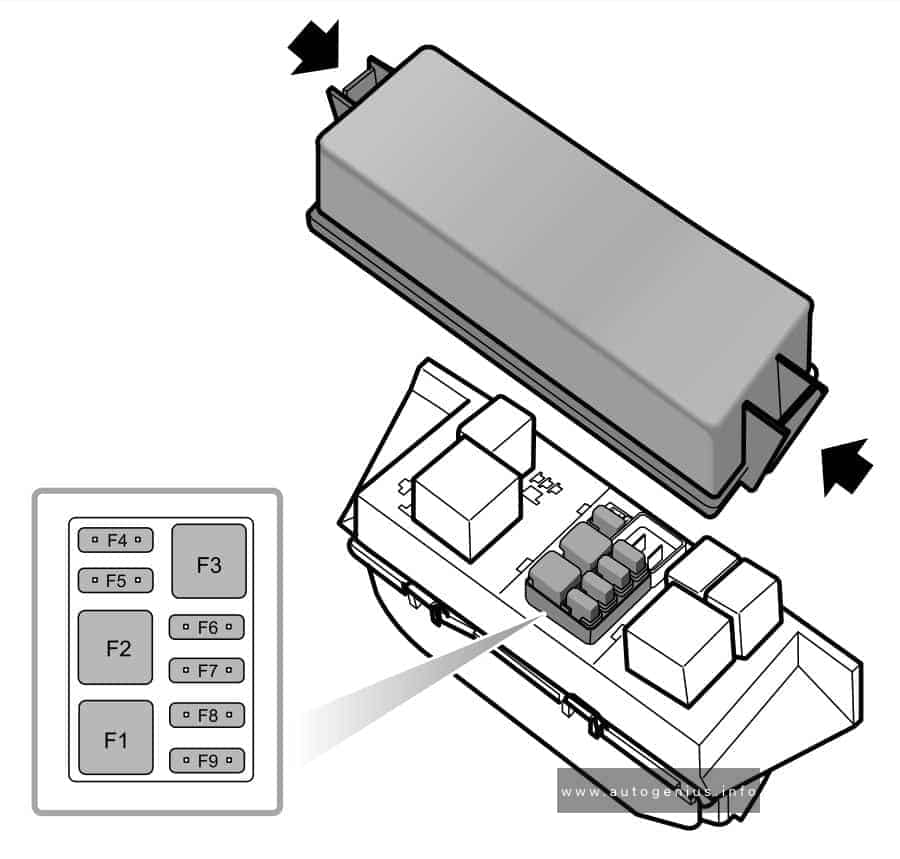
| F1 |
— |
— |
— |
— |
| F2 |
— |
— |
— |
— |
| F3 |
— |
— |
— |
— |
| F4 |
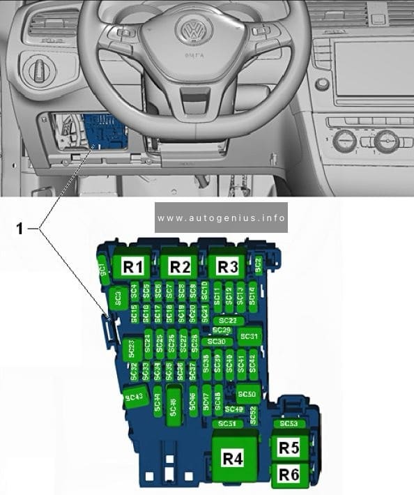
Fuse 4 on fuse panel C -SC4- |
10 |
Vehicle electrical system control module -J519-,
Anti-theft alarm system |
30 |
| F5 |
Fuse 5 on fuse panel C -SC5- |
5 |
Data bus on board diagnostic interface -J533- |
30 |
| F6 |
Fuse 6 on fuse panel C -SC6- |
5 |
Anti-theft alarm system sensor -G578- |
30 |
| F7 |
Fuse 7 on fuse panel C -SC7- |
10 |
Heater and A/C controls -EX21-
Heater control module -J65-
Climatronic control unit -J255-
A/C control module -J301-
Selector lever -E313-
Auxiliary engine coolant heater radio
frequency receiver -R149-
Rear window defogger relay -J9- |
30 |
| F8 |
Fuse 8 on fuse panel C -SC8- |
10 |
Rotary light switch -EX1- 30
Electro-mechanical parking brake button -E538-
Humidity, rain and light recognition sensor -G823-
Diagnostic connection -U31- |
30 |
| F9 |
— |
— |
— |
— |
| F10 |
Fuse 10 on fuse panel C -SC10- |
10 |
Front information display control head -J685- |
30 |
| F11 |
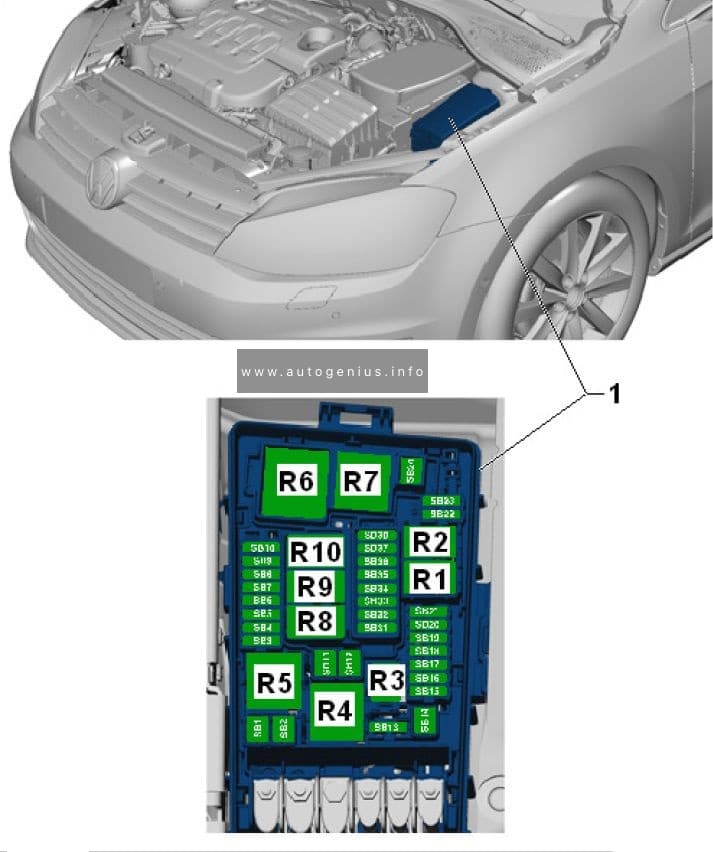
Fuse 11 on fuse panel B -SB11- |
15 |
All wheel drive control module -J492- |
30 |
| F12 |
Fuse 12 on fuse panel C -SC12- |
20 |
Information electronics control module 1 -J794- |
30 |
| F13 |
Fuse 13 on fuse panel C -SC13- |
15 |
Electronic damping control module -J250- |
30 |
| F14 |
Fuse 14 on fuse panel C -SC14- |
30 |
Fresh air blower control module -J126- |
30 |
| F15 |
Fuse 15 on fuse panel C -SC15- |
10 |
Electronic steering column lock control module
-J764- |
30 |
| F16 |
Fuse 16 on fuse panel C -SC16- |
7,5 |
Mobile communication 2-way signal amplifier -J984-
Antenna amplifier 3 -R112-
Voltage converter for USB charge module -A5- |
30 |
| F17 |
Fuse 17 on fuse panel C -SC17- |
5 |
Instrument cluster control module -J285-
Instrument cluster -KX2- |
30 |
| F18 |
Fuse 18 on fuse panel C -SC18- |
7,5 |
Rearview camera -R189-
Rear lid unlock switch -E165- |
30 |
| F19 |
Fuse 19 on fuse panel C -SC19- |
7,5 |
Access/start system interface -J965- |
30 |
| F20 |
— |
— |
— |
— |
| F21 |
— |
— |
— |
— |
| F22 |
— |
— |
— |
— |
| F23 |
Fuse 23 on fuse panel C -SC23- |
40 |
Vehicle electrical system control module -J519-
Right front headlamp -MX2- |
30 |
| F24 |
Fuse 24 on fuse panel C -SC24- |
30 |
Power sunroof control module -J245- |
30 |
| F25 |
Fuse 25 on fuse panel C -SC25- |
30 |
Driver door control module -J386- 1)
Left rear window regulator motor -V26- 1)
Front passenger door control module -J387- 2)
Right rear window regulator motor -V27- 2) |
30 |
| F26 |
Fuse 26 on fuse panel C -SC26- |
20 |
Vehicle electrical system control module -J519-
Front heated seat |
30 |
| F27 |
Fuse 27 on fuse panel C -SC27- |
30 |
Digital Sound System Control Module -J525- |
30 |
| F28 |
Fuse 28 on fuse panel C -SC28- |
20 |
Towing recognition control module -J345- |
30 |
| F29 |
— |
— |
— |
— |
| F30 |
Fuse 30 on fuse panel C -SC30- |
25 |
Left front seat belt tensioner control module -J854- |
30 |
| F31 |
Fuse 31 on fuse panel C -SC31- |
40 |
Vehicle electrical system control module -J519-
Left front headlamp -MX1- |
30 |
| F32 |
Fuse 32 on fuse panel C -SC32- |
7,5 |
Driver assistance systems front camera -R242-
Distance regulation control module -J428-
Parking aid control module -J446-
Parallel parking assistance control module –
J791- |
15 |
| F33 |
Fuse 33 on fuse panel C -SC33- |
5 |
Airbag control module -J234- |
15 |
|
|
|
Front passenger airbag -disabled- indicator
lamp -K145- |
|
| F34 |
Fuse 34 on fuse panel C -SC34- |
7,5 |
Rotary light switch -EX1-
Interior rearview mirror -EX5-
Tire pressure monitoring display button -E492-
Socket relay -J807-
Back-up lamp switch -F4-
Refrigerant circuit pressure sensor -G805-
Air quality sensor -G238-
Electro-mechanical parking brake button –
E538- |
15 |
| F15 |
Fuse 35 on fuse panel C -SC35- |
10 |
Diagnostic connection -U31-
Headlamp range control and instrument
illumination regulator -EX14-
Automatic dimming interior rearview mirror -Y7
–
Cornering lamp and headlamp range control
module -J745-
Left headlamp beam adjustment motor -V48-
Right headlamp beam adjustment motor -V49- |
15 |
| F36 |
Fuse 36 on fuse panel C -SC36- |
10 |
Right daytime running lamp and parking lamp
control module -J861- |
15 |
| F37 |
Fuse 37 on fuse panel C -SC37- |
10 |
Left daytime running lamp and parking lamp
control module -J860- |
15 |
| F38 |
Fuse 38 on fuse panel C -SC38- |
20 |
Towing recognition control module -J345- |
30 |
| F39 |
Fuse 39 on fuse panel C -SC39- |
30 |
Front passenger door control module -J387-
Right rear window regulator motor -V27- 1)
Driver door control module -J386- 2)
Left rear window regulator motor -V26- 2) |
30 |
| F40 |
Fuse 40 on fuse panel C -SC40- |
20 |
Cigarette lighter -U1-3)
12 V socket -U5-
12 V socket 2 -U18-
12 V socket 3 -U19- |
15/30 4) |
| F41 |
Fuse 41 on fuse panel C -SC41- |
10 |
Steering column electronics control module -J527- |
30 |
| F42 |
Fuse 42 on fuse panel C -SC42- |
40 |
Vehicle electrical system control module -J519-
Central locking system |
30 |
| F43 |
Fuse 43 on fuse panel C -SC43- |
30 |
Vehicle electrical system control module -J519- |
30 |
| F44 |
Fuse 44 on fuse panel C -SC44- |
15 |
Towing recognition control module -J345- |
30 |
| F45 |
Fuse 45 on fuse panel C -SC45- |
15 |
Driver seat lumbar support adjustment switch -E176-
Driver seat adjustment control head -E470-
Front passenger seat adjustment control head -E471-
Front passenger seat lumbar support adjustment switch -E177- |
30 |
| F46 |
— |
— |
— |
— |
| F47 |
Fuse 47 on fuse panel C -SC47- |
15 |
Rear window wiper motor -V12- |
15 |
| F48 |
— |
— |
— |
— |
| F49 |
Fuse 49 on fuse panel C -SC49- |
5 |
Clutch pedal position sensor -G162-
Starter relay 1 -J906-
Starter relay 2 -J907- |
15 |
| F50 |
— |
— |
— |
— |
| F51 |
Fuse 51 on fuse panel C -SC51- |
25 |
Right front seat belt tensioner control module -J855- |
15 |
| F52 |
— |
— |
— |
— |
| F53 |
— |
— |
— |
— |
1) Only for left-hand drive vehicles
2) Only for right-hand drive vehicles
3) Smoking package
4) Depending on equipment |