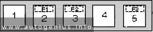
Right taillight
Right parking lamp
Left license plate lamp
Right license plate lamp
7.5
7
Left taillight
Left parking light
7.5
8
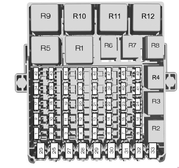
Engine 132.9:
Secondary air injection pump relay
ME-SFI [ME] control unit
Electronic selector lever module control unit
Automated manual transmission control unit
Cylinder 1 ignition coil
Cylinder 2 ignition coil
Cylinder 3 ignition coil Engine 660.9:
CDI control unit
Electronic selector lever module control unit
Automated manual transmission control unit Engine 780.009: High-voltage battery heater
25
9
Engine 132.9:
O2 sensor downstream of CAT
O2 sensor upstream of CAT
Adjustable camshaft timing solenoid
External air shutoff valve
Activated charcoal canister shutoff valve
EGR switchover valve (with engine 132.910)
Tank vent valve
Pressure regulator valve(for engine 132.930) Engine 780.009: Electric drive and high-voltage charger fan motor Engine 660.9: CDI control unit
7.5
10
Engine 132.9:
O2 sensor upstream of CAT
Secondary air injection pump switchover valve
Cylinder 1 fuel injection valve
Cylinder 2 fuel injection valve
Cylinder 3 fuel injection valve Engine 780.009:
Electric drive and high-voltage charger coolant pump
Battery cooling system coolant pump Engine 660.9:
Hot film mass air flow sensor
O2-sensor upstream of CAT
CDI control unit
Glow output stage
EGR switchover valve
15
11
ESP control unit
25
12
Instrument cluster
Additional instruments
Microwave sensor
Rain sensor / light sensor
Alarm siren with inclination sensor
Left turn signal lamps/brake light relay
Right turn signal lamps/brake light relay
Mirror heater relay
Automated manual transmission control unit
TPM [RDK] control unit
Combination switch
Cockpit switch group
Data link connector
Starter-alternator control unit
STH radio remote control receiver (engine 780.009)
Rear fog light relay
10
13
Spare fuse
15
14
Refrigerant compressor
Charge air fan motor
15
15
Smart radio 9
Smart radio 10
Front interior lamp
Soft top OPEN relay
Soft top CLOSE relay
15
16
Engine 132.9:
Fuel pump with fuel gauge sensor
ME-SFI [ME] control unit Engine 660.9:
Fuel pump with fuel gauge sensor
CDI control unit Engine 780.009: Blower motor relay 1
15
17
Rear-end door wiper motor
15
18
Instrument cluster
Yaw rate sensor for lateral and longitudinal acceleration
Seat occupied recognition pressure sensor
Automatic child seat recognition airbag OFF indicator lamp
Restraint systems control unit
ESP control unit
Steering angle sensor
Steering assist control unit
Driver side seat belt buckle restraint systems switch
Front passenger-side seat belt buckle restraint systems switch
10
19
Engine 132.9:
ME-SFI [ME] control unit
Automated manual transmission control unit
Data link connector
TPM [RDK] control unit
Starter-alternator control unit Engine 780.009: Data link connector Engine 660.9:
CDI control unit
Automated manual transmission control unit
Data link connector
7,5
20
Smart radio 9
Smart radio 10
Heater/air conditioning operating unit
Front seat heater (SIH) control unit
Right wiper switch
Outside mirror adjustment switch
Electrically adjustable and heated outside mirrors
Soft top operation
Electronic selector lever module control unit
10
21
Interior socket
15
22
Left low beam
7.5
23
Right low beam
7.5
24
Engine 132.9: Electronic selector lever module control unit Engine 132.9, 660.9, 780.009:
Rear fog light relay
Stop light switch
15
25
Right high beam
7.5
26
Left high beam
7.5
27
Engine 132.9: ME-SFI [ME] control unit
7.5
28
Heated rear window
40
29
Soft top OPEN relay
Soft top CLOSE relay
30
30
Engine 132.9, 660.9: Automated manual transmission control unit Engine 780.009: High-voltage battery and interior fan motor
40
31
Horn
Right door CL motor
Left front door central locking motor
Rear-end door CL [ZV] motor
Fuel filler flap CL [ZV] motor
Horn switch
20
R1
Engine 132.9, 660.9: Mirror heater relay
7.5
R2
Engine 132.9: Stop light switch
7.5
R3
Vacant
–
R4
Engine 780.009: Mirror heater relay
7.5-
R5
Engine 780.009:
High-voltage charger control unit
External socket communications control unit
7.5
R6
Engine 780.009: EVCM electric vehicle control unit
Audi 200 (C3; 1983 – 1991) – fuse and relay box diagram
Year of production: 1983, 1984, 1985, 1986, 1987, 1988, 1989, 1990, 1991
This article covers the second-generation Audi 200 (C3), produced from 1983 to 1991. It includes fuse box diagrams for the 1983, 1984, 1985, 1986, 1987, 1988, 1989, 1990 and 1991 models, provides details on the location of the fuse panels inside the vehicle, and explains the function and layout of each fuse.
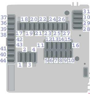
Fuses box diagram
Audi 200 (C3; 1983 – 1991) – fuse and relay box diagram
Audi 100 (C3; 1983 – 1991) – fuse and relay box diagram
Year of production: 1983, 1984, 1985, 1986, 1987, 1988, 1989, 1990, 1991
This article covers the second-generation Audi 100 (c3), produced from 1983 to 1991. It includes fuse box diagrams for the 1983, 1984, 1985, 1986, 1987, 1988, 1989, 1990 and 1991 models, provides details on the location of the fuse panels inside the vehicle, and explains the function and layout of each fuse.
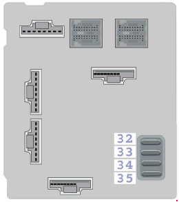
Fuses box diagram
Audi 100 (C3; 1983 – 1991) – fuse and relay box diagram
Year of production: 1990, 1991, 1992, 1993, 1994, 1995, 1996, 1997, 1998, 1999, 2000, 2001, 2002, 2003
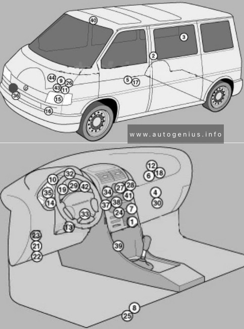
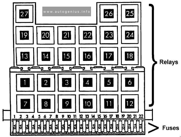
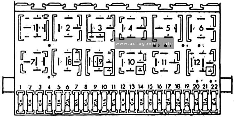
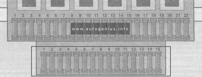
Volkswagen Transporter T4 – represents the 4th generation of the legendary Transporter series. This model was produced in 1990, 1991, 1992, 1993, 1994, 1995, 1996, 1997, 1998, 1999, 2000, 2001, 2002 and 2003 with diesel and gasoline engines with different wheelbases: short and long, and with different roof height. Also on the T4, Volkswagen continued its lineup of luxury Caravelle, California and Multivan models. In this article, we will show the location of all electronic control sides and a detailed designation of the purpose of fuses and relays Volkswagen T4 with box diagrams in which they are located.
Air conditioning control unit 1 – with automatic temperature control – in the heater control panel, front
2
Air conditioning control unit 2 – with automatic temperature control – in the heater control panel, rear – central pillar
3
Evaporator Fan Control Unit (A / C) – With Rear A / C – Behind Right Rear Trim Panel
4
Air conditioning / heater fan motor control unit 1 – with automatic temperature control – front – fan unit
5
Air conditioning / heater blower motor control unit 2- with automatic temperature control – rear- bottom of the body, in the center
6
Aerial amplifier – behind the dash, passenger side
7
Alternator resistor – near additional relays – CV / AUF, with alternator 150A / automatic transmission / automatic temperature control – behind the central part of the dashboard
8
Additional battery – under the driver’s seat
9
Accumulator battery
10
Central locking signal control unit – behind the dashboard
11
Cruise control unit (with throttle motor) – cruise control is controlled by the ECM
12
Electronic cruise control module (without throttle motor) – behind dash, passenger side
13
Diagnostic connector (DLC) – instrument panel, driver’s side
14
Diagnostic unit – 05/99 (except for AAC / ABL / AET / AES / AJA) – in the instrument cluster
15
Cooling Fan Motor Relay – Behind Left Headlight
16
Cooling Fan Motor 1/2 Resistor – Behind Left Headlight
17
Coolant heater control unit (with additional coolant heater – D3W / B4W / D4W) – in the heater – underbody, in the center
18
Coolant heater control unit (with optional coolant heater – B7W / D7W) – behind the dash, passenger side
19
Engine oil pressure warning buzzer – in instrument cluster control unit
Windshield wiper / washer, heaters for windshield washer nozzles (05/01)
6
30
Air conditioning system, heater fan motor
7
10
Front right side / rear right side lamps
8
10
Lamps front left / rear left
9
20
Heated rear window, heated outside mirror
10
15
Fog lights
11
10
Left headlamp-high beam
12
10
RH headlamp-high beam
13
10
Sound signal
14
10
ABS system (with ESP), automatic transmission control system, additional equipment, central locking, cruise control system, power windows, power rear-view mirrors on the doors, reverse light (s)
Heater blower motor relay – automatic temperature control
5
(152)
Heater radiator coolant valve relay (rear heater)
6
(38)
Air intake changeover actuator relay (A / C / heater)
7
(53)
Alternator relay (AES, with 150A alternator)
8
(53)
Alternator relay (ACV / AUF, with alternator 150A / automatic / automatic temperature control)
9
(175)
Start inhibit switch relay / reversing lamp relay
10
(87)
Wheel hub connection control unit
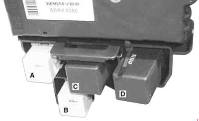
Another unit can be located under the driver’s seat. The following items may be located there: (214/426) Relay for additional battery, (403) Relay for additional heater, (30A) Additional liquid heating system, (5A) Sockets , etc.
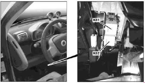
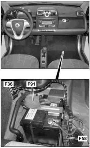
Engine compartment
Fuse box location
This unit is located on the cover in front of the battery.
Year of production: 2006, 2007, 2008, 2009, 2010, 2011
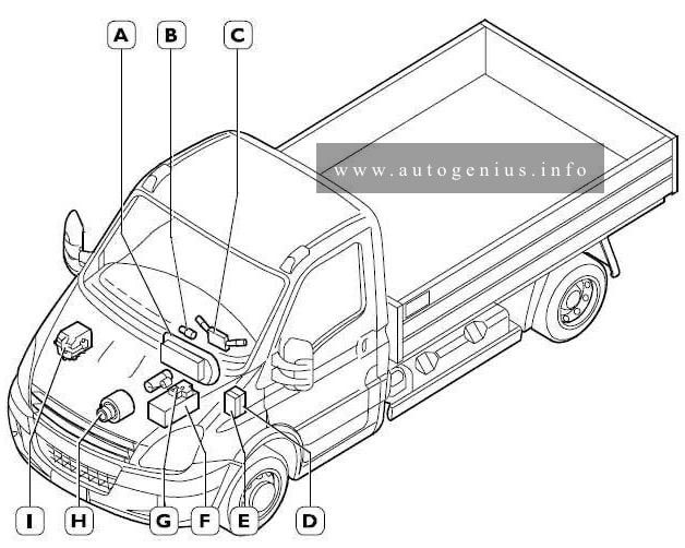
This article covers the second-generation Iveco Daily IV (4th generation), produced from 2006 to 2011. It includes fuse box diagrams for the 2006, 2007, 2008, 2009, 2010 and 2011 models, provides details on the location of the fuse panels inside the vehicle, and explains the function and layout of each fuse.
A. Instrument cluster
B. Key switch
C. Steering column switch unit
D. Interconnection central unit ”CPL”
E. Body Computer
F. Battery
G. Positive (+30) distribution central unit ”CBA”
H. Alternator
I. (Engine) interconnection central unit ”CVM”.
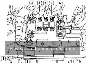
Engine compartment
Fuse box diagram (Positive connection central unit – CBA)
Iveco Daily(IV; 2006 – 2011) – fuse and relay box doagram – engine compartment – positive cinnection central unit (CBA)
Assignment of the fuses in the engine compartment (positive cinnection central unit – CBA)
№
A
Function
1
500
Positive +30 for alternator starter
2
150
Positive for engine opening central unit ”CVM”
3
70
Positive +30 for ”CPL”
4
70
Positive +30 for ”CPL”
5
50
Positive +30 for box OPT
6
–
Positive +30 for ”CPL” – OPT prearrangement
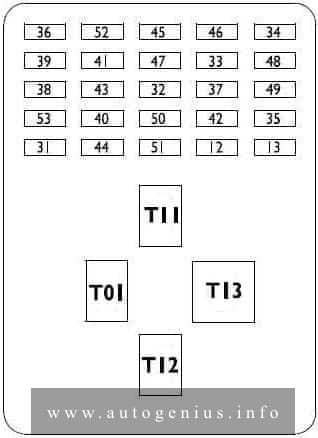
Passenger compartment
Fuse box diagram (Instrument panel interconnection central units – CPL)
Iveco Daily(IV; 2006 – 2011) – fuse and relay box doagram – passenger compartment – instrument panel interconnection central units (CPL)
Assignment of the fuses in the passenger compartment (instrument panel interconnection central units – CPL)
№
A
Function
12
7.5
Right hand dipped headlight
13
7.5
Left hand dipped headlight – headlamp attitude rectifier
31
3
Relay T08-T17 in CVM and BC
32
15
Rotating-translating door
33
15
Air heater /Cigarette lighter
34
20
Socket
35
10
ABS8 or ESP8. Telma
36
20
Central locking
37
5
Switches for stop lights and various loads under 15
38
10
BC / Roof lamps internal relays power supply
39
15
Car radio – chrono-tachograph
40
10
Rh heated rear window
41
10
Lh heated rear window
42
5
Reverse lights switch
43
20
Windscreen wiper
44
–
AVAILABLE
45
–
AVAILABLE
46
–
AVAILABLE
47
25
Driver window winder
48
25
Passenger window winder
49
15
ECU for climate control system, car radio, heated seats
50
5
Airbag
51
5
Chrono-tachograph
52
–
AVAILABLE
53
7.5
Instrument cluster, rear fog lights
Relay
T-01
Right and left hand dipped headlights
T-11
Heated rear window
T-12
Cigarette lighter / socket / heater or climate control system
T-13
Power release from key
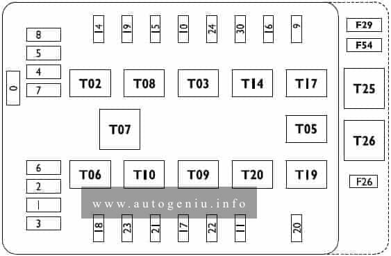
Fuse box diagram (Interconnection central unit – CVM)
Iveco Daily(IV; 2006 – 2011) – fuse and relay box doagram – Interconnection central unit (CVM)
Assignment of the fuses in the interconnection central units – CVM)
№
A
Function
0
60
Ignition glow plugs
1
40
ABS8 or ESP8
2
30
ABS8 or ESP8
3
30
ECU ESV1 (automatic gearbox)
4
30
ECU ESV1 (automatic gearbox)
5
30
Start-up switch
6
20
Heated mirrors and windscreen
7
20
Side marker lamps
8
30
Heater or climate control system fans
9
20
Windscreen washer
10
7.5
Horn
11
10
EDC16 (secondary loads)
14
7.5
Right hand full beam headlight
15
7.5
Left hand full beam headlight
16
5
EDC16, T02, T14, Additional heater
17
15
EDC16 (primary loads)
18
10
ECU ESV1 (automatic gearbox)
19
5
Baruffaldi
20
25
Fuel filter heater
21
15
Fuel pump
22
25
EDC16 (primary loads)
23
10
Additional heater
24
15
ECU ESV1 (automatic gearbox), PTO
26
10
Trailer socket
29
40
Air spring suspensions
30
15
Left and right hand front fog lights
54
40
Air spring suspensions
T02
20
Right and left hand full beam headlights
T03
20
Horn
T05
20
Baruffaldi power supply
T06
20
Heater / mirrors / windscreen
T07
20
Side marker lamps
T08
20
Heater or climate control system fans
T09
20
EDC16 (main relay)
T10
20
Fuel pump
T14
20
Left and right hand front fog lights
T17
20
Windscreen washer
T19
20
Fuel filter heater
T20
20
Diagnosis MODUS
T25
10/20
Windscreen wiper on/off
T26
10/20
Windscreen wiper 1st / 2nd speed
(F26, F29, F54, T25, T26) in container, out of central unit
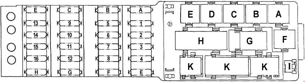
Year of production: 1985, 1986, 1987, 1988, 1989, 1990, 1991, 1992, 1993, 1994, 1995, 1996
Fuse box
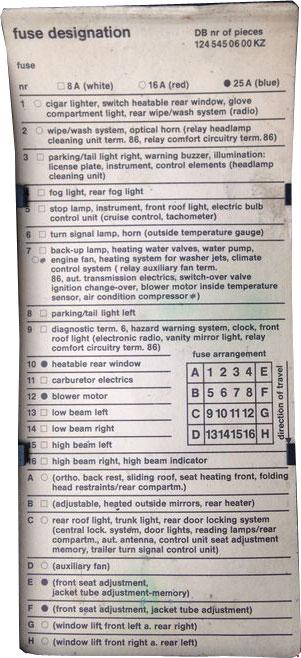
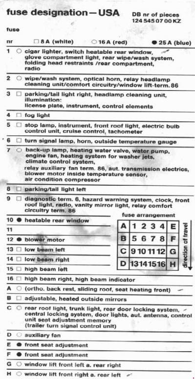
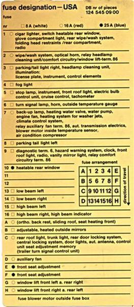
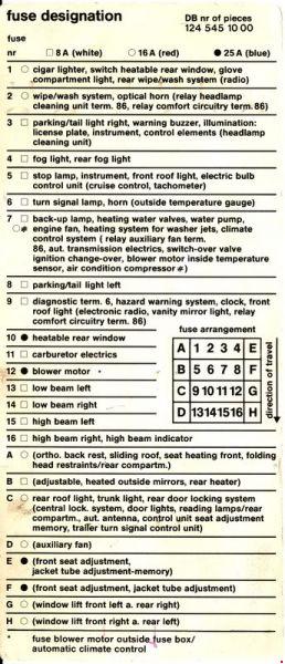
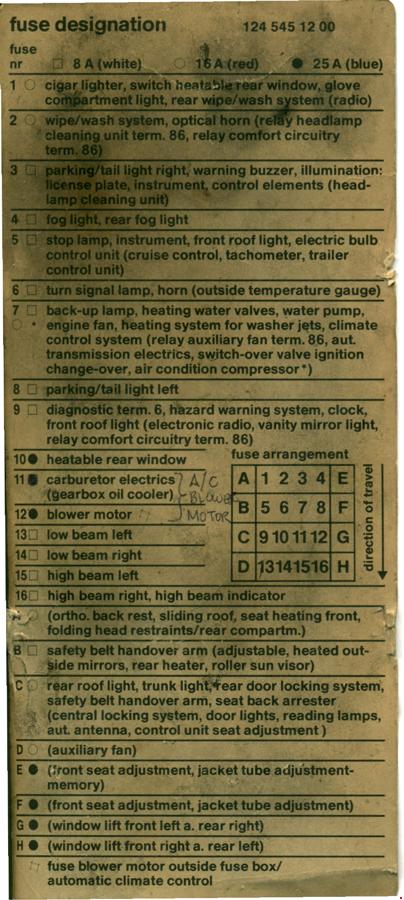
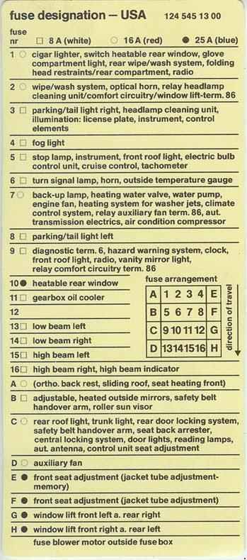
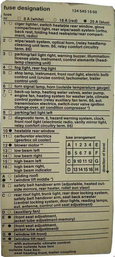
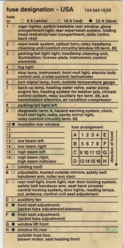
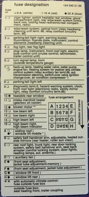
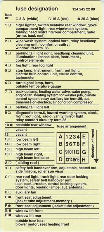
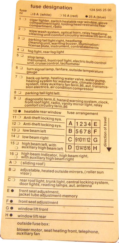
Mercedes-Benz E- Class w124 – fuse box diagram
№
A
Function
1
16
Glove Box Lamp Cigar Lighter
Radio
Rear Head Restraint System
Rear Defogger
Rear Wiper/Washer System
Rear window sun shade motor
Sliding/pop-up roof
Central locking system/orthopedic backrest
SBE control module (Cabriolet)
HS control module Conveniece feature
2
16
Wiper/Washer
Headlamp Wiper/Washer
Headlamps/Fog Lamps
Power Seats
Power Windows
Convenience feature
3
8
Lamps: Park/Tail/Side Marker/ License (Right)
Illumination: License plate, instrument cluster, control elements, radio, cigar lighter
Warning buzzer
Headlamp wiper/washer
Electrically adjustable and heated outside rearview mirrors
HS control module
Folding rear head restraints
Rear backrest/head restraints
Sliding/pop-up roof
Seat heater switch
RB switch
Power soft top switch
Front seat adjustment with memory
Seat belt warning module
4
8
Fog lamp
Rear fog lamp
5
8
Stop lamp switch
Front dome lamp
Tachometer
Inductive speed sensor
Instrument cluster
Exterior lamp failure monitoring module
Cruise control
Warning module
RB control lamp
RB switch
Power soft top
Seat belt warning module
Daytime running lamp control module
6
8
Turn Signal Outside temperature gauge
Fanfare horns
Injectors
Starter switch
Instrument cluster
ABS warning lamps
ABS MIL
TWC malfunction control module Roll bar
Overvoltage protection relay module Ignition coils
Preglow time-limit relay module Generator charge indicator lamp
7
8
161)
Automatic Climate Control
Automatic transmission electric:
Kickdown solenoid valve
Transmission mode valve
Data link connector, terminal 16
Throttle valve actual valve potentiometer
Blower motor
Heater/climate control system:
Electromagnetic clutch
A/C compressor
Auxiliary fan relay, terminal 86 Auxiliary fan relay (stage 2)
O2S (after TWC) heater relay module
Climate control system
Monovalve, duovalve
Auxiliary coolant pump
Fresh/recirculated air flap switchover valve (switchover valve block)
Rest relay module
Stationary heater control module
Bypass valve
Purge control valve/fuel tank rent valve
Upshift delay solenoid valve
Heated windshield washer nozzle
Heated windshield washer system
Kickdown cut-out relay module/compressor
HFM-SFI control module
EGR switchover valve 2
Resonance intake manifold switchover valve
Air pump switchover valve
Adjustable camshaft timing solenoid
Electromagnetic air pump clutch
Control/function indicator lamp
ASD/ASR/4-MATlC Backup lamp
Blower motor (auto. A/C)
Blower regulator (auto. A/C)
16
ATA Control module
12
25
Anti-Theft Alarm System
13
8
Headlamps (Left Low Beam)
Anti-Theft Alarm System
14
8
Headlamps (Right Low Beam)
Anti-Theft Alarm System
15
8
Headlamps (Left High Beam)
16
High beam left with auxiliary high beam left
16
8
Headlamps (Right High Beam)
High Beam Indicator
16
High beam right with auxiliary high beam right
High Beam Indicator
A
16
Sliding Roof
Heated Seats
Orthopedic Seats
Folding head restraints/rear compartment
25
Center power window optional
8
Power soft top control module optional
RB control module
B
8
Seat belt extender system
Anti-theft alarm system
Automatic dimming inside rearview mirror
Seat belt warning module, terminal 86
IRCL control module
Adjustable, heated outside mirrors
C
16
Anti-Theft Alarm System
Radio tuner/Amplifier
Audio Power Amplifiers
CD Changer
Automatic antenna
CD-Player
Rear dome light (Station wagon)
Entrance/exit lamp
Anti-theft alarm system
Seat belt extender (Coupe)
Tailgate lock switch (Station wagon)
Trunk lamp (except station wagon)
Rear reading lamps
IRCL control module
CF control module
Central Locking System
Sound system
Backrest lock (Coupe)
D
16
Auxiliary fan/preresistor
E
25
Front passenger power seat:
Head restraint motor
Right front/rear power seat motor group with memory
Backrest motor
Driver power seat:
Head restraint motor
Left front/rear power seat motor group with memory
Backrest motor
F
25
Telescopic Steering Column
Front passenger power seat:
Seat forward/backward motor
Right front/rear power seat motor group with memory
Driver power seat:
Seat forward/backward motor
Left front/rear power seat motor group with memory
G
16
124 545: 0600, 0700, 0900, 1000: Power Windows (Front Left and Rear Right)
25
124 545: 1200, 1300: Power Windows (Front Left and Rear Right)
124 545: 1500, 1600, 2100, 2200, 2500, 2700: Power Windows (Front)
H
16
124 545: 0600, 0700, 0900, 1000: Power Windows (Front Right and Rear Left)
25
124 545: 1200, 1300: Power Windows (Front Right and Rear Left)
124 545: 1500, 1600, 2100, 2200, 2500, 2700: Power Windows (Rear)
Relay
A
K5 Power Seat Relay
B
К10 Auxiliary Fan Preresistor Relay
K9kl Auxiliary Fan Relay (as of my 1992, models 400E/500E)
C
K9 Auxiliary Fan Relay
K9k2 Auxiliary Fan Relay Preresistor (as of my 1992, models 400E/500E)
D
K2 Headlamp Washer Relay
E
F14 Auxiliary Fuse Holder
K17 Air Injection Relay (as of my 1992, models 400E/500E)
F
K4 Power Window Relay
K24 Convenience Relay (as of my 1990)
G
K18 Seat Belt Warning Relay (Сoupe model only)
K29/1 First Gear Start Relay (Сoupe model only)
H
N10 Combination Relay
I
V1 Power Seat Diode (Replaced by K24 as of by 1990)
V5 Parking Brake/ASR/Electronic Accelerator (as of my 1992, models 400E/500E)
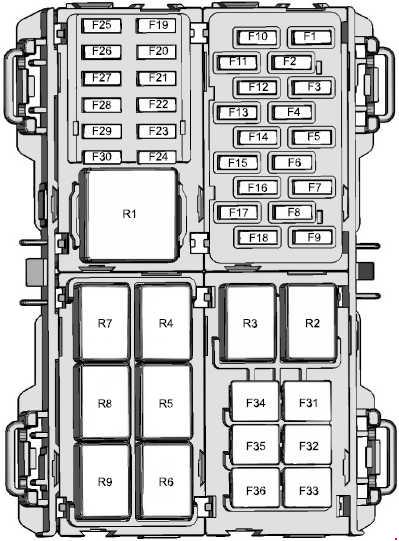
up to 2012: Electronic mirror, A/C clutch, Engine compartment fuse panel
7,5
as of 2013: Auto-dimming interior mirror, Autowipers, Heater relay control
F3
7.5
Instrument cluster
F4
7.5
Passenger airbag deactivation indicator, Occupant classification system
F5
15
Diagnostic connector
F6
10
Backup lamp
F7
7.5
Instrument panel display, Intelligent access (IA) antenna (up to 2012), Manual climate controls (up to 2012), Information and entertainment display (as of 2013)
F8
7,5
as of 2011: Front dome lamp (up to 2012), Moon roof switch
F9
20
Keyless vehicle module
F10
15
Radio, SYNC® module
F11
20
Front wipers, Body control module (BCM)
F12
20
up to 2012: Tire pressure monitoring system (TPMS)
7,5
as of 2013: Climate control
F13
15
Rear wiper, BCM
F14
20
up to 2012: Intelligent access module as of 2013: Keyless entry, keyless starting
F15
15
Washer pump
F16
15
up to 2011: Global positioning system (GPS) module
7,5
as of 2011-2012: Electric exterior mirrors, power windows
5
as of 2013: Electric exterior mirrors, power windows
F17
7.5
up to 2012: Heated seat relay
15
as of 2012: Heated seats
F18
10
Stop lamps, Turn signals (up to 2012)
F19
7.5
Instrument cluster, Radio (up to 2011)
F20
10
Airbag module
F21
10
up to 2012: Body control module, Climate control, Passive anti-theft system transceiver, Electronic power steering module, Instrument cluster, Engine compartment fuse panel
7,5
as of 2012: Body control module – ignition switch, Climate control, Passive anti-theft system transceiver, Electronic power steering module, Instrument cluster, Engine compartment fuse panel as of 2013: Electronic power assisted steering, Instrument cluster, Ignition, Wipers, Passive anti-theft system
F22
7.5
Accelerator pedal position sensor, Powertrain control module (PCM), Gear shifter (up to 2012), Anti-lock brake system (ABS) ignition feed, Stability assist (as of 2013)
F23
10
up to 2012: Transmission control unit ignition feed, Tire pressure monitoring system ignition feed
7,5
as of 2013: Transmission control unit.
F24
7.5
up to 2011: Front dome lamp, Moon roof switch as of 2013: Audio unit
F25
7.5
Exterior mirrors
F26
7.5
up to 2011: Tire pressure monitoring system as of 2013: Central locking system.
F27
—
Not used
F28
—
Not used
F29
—
Not used
F30
—
Not used
F31
30
Power windows
F32
20
Battery back-up sounder, Rear auxiliary power points
F33
20
Power points
F34
30
Power windows
F35
20
Moon roof
F36
—
Not used
Relay
R1
Ignition relay
R2
up to 2012: Left rear stop/turn lamp relay
R3
up to 2012: Right rear stop/turn lamp relay
R4
Driver heated seat relay
R5
Passenger heated seat relay
R6
Accessory mode remote keyless starting
R7
Ignition mode remote keyless starting
R8
Battery saver relay
Battery back-up sounder
R9
Accessory delay
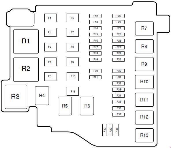
Engine Compartment Fuse Box (Europe ’08-’17; North America ’10-’11)
Ford Fiesta – fuse box diagram – engine compartment – Europe ’08 – ’17; North America ’10 – ’11
No.
A
Circuits protected
1
40
Anti-lock braking system module
30
Anti-lock braking system, electronic stability program module (Europe only)
2
60
Europe: Cooling system fan high speed
50
North America: Transmission control module (TCM)
3
40
Cooling system fan
30
Cooling system fan low speed (Europe only)
4
30
Heater blower
40
North America: Heater blower relay, Climate controls
5
60
Passenger compartment fuse box supply (battery)
6
30
Body control module
7
60
Passenger compartment fuse box supply (ignition)
8
50
Europe; as of 2012: Automatic transmission
60
Europe; up to 2012: Glow plugs
30
North America: Fuel pump
9
60
Europe: Heated windshield
20
North America: ABS module valve
10
–
Not used
11
30
Starter relay
12
10
High beam left-hand relay
13
10
High beam right-hand relay
14
10
Europe: Water pump North America: Left headlamp (low beam)
15
10
Europe: Ignition coils North America: Right headlamp (low beam)
16
15
Europe: Powertrain control module, high and low cooling fan North America: A/C clutch relay, Mass air flow (MAF) sensor, Powertrain control module (PCM), Fuel injectors, Vehicle speed sensor (VSS), Variable camshaft timing, Canister purge
17
15
Gasoline Engines: Heated oxygen sensors
20
Diesel Engines: Power supply module
18
10
Europe; up to 2012: FN (Automatic) transmission
15
North America: Ignition coil
19
7.5
Europe; as of 2012: Air conditioning compressor
20
–
Not used
21
7.5
Europe; as of 2012: Cooling system fan (1.6L Duratorq-TDCi)
22
15
Europe; up to 2012: Lighting control battery supply North America: BCM – exterior lighting
23
15
Europe: Front fog lamps
7,5
North America: Low beam relay
24
15
Direction indicators
25
15
Europe; as of 2012: Exterior lighting left-hand side North America: Low beam relay, Daytime running lights
10
Europe; up to 2012: Daytime running lamps
26
15
Europe; as of 2012: Exterior lighting right-hand side
7.5
Europe; up to 2012: Electric exterior mirrors switch, electric folding mirrors, power window (driver’s door) North America: Power mirror switch, Driver window switch
27
7.5
Europe: Powertrain control module North America: TCM, PCM, Natural vacuum leak detection
28
20
Europe: Anti-lock braking system, electronic stability program
29
10
Air conditioning clutch
30
–
Not used
31
20
North America: Low beam relay
32
20
Horn, battery saver, keyless vehicle module
33
20
Heated rear window
34
20
Europe: Fuel pump relay, diesel fuel heater
35
15
Europe; as of 2012: Category one alarm system
36
7.5
Europe; as of 2012: Automatic transmission controller
37
25
Europe; as of 2012: Front door module left-hand side
38
25
Europe; as of 2012: Front door module right-hand side
39
25
Europe; as of 2012: Rear door module left-hand side
40
25
Europe; as of 2012: Rear door module right-hand side
Relay
R1
Europe: Cooling system fan
R2
Europe: Heated windshield
R3
Europe: Power control module
R4
High beam
R5
Europe; up to 2012: Dipped beam North America: PCM relay
R6
Daytime running lamps
R7
Engine cooling fan
R8
Starter
R9
Air conditioning clutch
R10
Europe: Front fog lamps North America: Reverse light relay
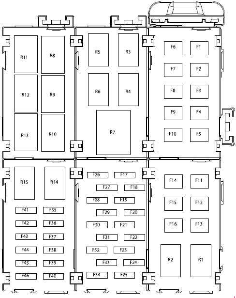
1.0L EcoBoost (as of 2013): High-speed cooling fan
14
–
Not used
15
–
Not used
16
–
Not used
17
20
High beam
18
15
as of 2013: Powertrain control module
19
20
as of 2013: Front fog lamps up to 2012: Low beam relay
20
15
Heated exhaust gas oxygen sensor, Catalyst module sensor
21
7.5
as of 2013: High beam up to 2012: Low and High beams coil relay control
22
15
as of 2013: Ignition coll
20
1.0L and 1.6L EcoBoost (as of 2013): Ignition coll
15
up to 2012: Mass air flow (MAF) sensor, Powertrain control module (PCM), Fuel injectors, Vehicle speed sensor (VSS), Variable camshaft timing, Canister purge
23
15
as of 2013: Right-hand exterior lamps up to 2012: Daytime running lights
24
10
as of 2013: Emissions system
25
15
as of 2013: Left-hand exterior lamps up to 2012: BCM – exterior lighting
26
20
Horn. Battery back-up sounder. Interior lamps
27
7.5
1.6L Flex-fuel (as of 2013): Engine cold start system module
15
1.0L EcoBoost (as of 2013): Water pump, Active grill shutter
28
15
Direction Indicators
29
20
as of 2013: Compressed natural gas, fuel control module
30
10
Air conditioning clutch
31
–
Not used
32
7.5
Powertrain control module. Transmission control unit
33
10
as of 2013: Fuel Injectors
7.5
1.0L and 1.6L EcoBoost (as of 2013): Mass air flow sensor
15
up to 2012: Ignition coil
34
30
as of 2013: Heated exterior mirrors up to 2012: BCM – rear window defroster
35
10
as of 2013: Left-hand fog lamp up to 2012: Left headlamp (low beam)
36
10
as of 2013: Right-hand fog lamp up to 2012: Right headlamp (low beam)
37
10
Left-hand high beam
38
10
Right-hand high beam
39
2
up to 2012: Natural vacuum leak detection
40
–
Not used
41
–
Not used
42
–
Not used
43
–
Not used
44
–
Not used
45
–
Not used
46
–
Not used
Relay
R1
as of 2013: Compressed natural gas fuel system
R2
Not used
R3
Powertrain control module
R4
Blower motor
R5
Cooling fan
R6
Air conditioning clutch
R7
1.0L and 1.6L EcoBoost (as of 2013): High-speed cooling fan
R8
up to 2012: Daytime running lamp
R9
Engine start Inhibitor
R10
High beam
R11
as of 2013: Front fog lamps up to 2012: Low beam relay
R12
Reversing lamp
R13
Fuel pump
Engine Compartment Fuse Box (North America ’15-’17)
Ford Fiesta – fuse box diagram – engine compartment – North America ’15 – ’17
Year of production: 2005, 2006, 2007, 2008, 2009, 2010, 2011
Fuse box on the dashboard
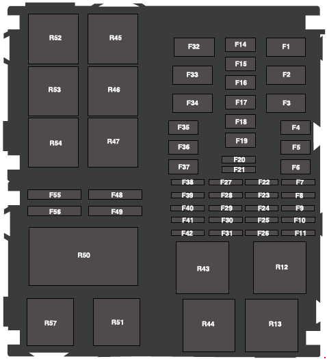
Alfa Romeo 159 – fuse box – dashboard
№
A
Function
12
15
Right dipped beam headlight
13
15
Left dipped beam headlight
31
7.5
Supply + key for relay coils of engine compartment control unit/dashboard control unit/Body Computer
32
15
Driver’s door branch point/passenger’s door branch point/ignition device
33
20
Rear left window control/boot node
34
20
Rear right window control/boot node
35
7.5
Reversing light/Brake light
36
20
Supply of boot node/locks actuators
37
7.5
Third brake light
Positive under key for stop lights/third stop/instrument/lights direction
38
15
Boot opening
39
10
Front/rear ceiling light
Supply + battery for air conditioner, ceiling lights, volumetric alarm, EOBD system diagnostic socket
40
30
Heated rear window
41
7.5
Defrosting of external mirrors/heated windshield relay coil
42
–
–
43
30
Windshield wiper/washer
44
10
Front cigar lighter on central console
45
15
Supply of socket in the boot
46
20
Sunroof
47
20
Power supply of driver door node
48
30
Power supply of passenger door nodes
49
7.5
Front ceiling light
+ Key for wheel node/Sunroof control unit/Front and rear ceiling lights/Cvs/Blue&Me node/Volumetric/Left and right seat
50
–
–
51
7.5
Supply under key for Telematic info node/Automatic gearbox node/Additional heater/Left dashboard controls/ START/STOP button, Parking sensors control unit/Electrochromatic mirror/Blue&Me node/Car radio prearrangement/AQS/Cruise Control
52
15
Rear window wiper/Rear lighter
53
10
Direction indicators
Hazard lights
Instrument panel branch point
Fuse box on the battery positive pole
Alfa Romeo 159 – battery positive pole
№
A
Function
70
150
Engine housing control unit services
71
70
Instrument panel control unit
72
50
Additional heater (passenger compartment water heating 600W) (diesel versions)
73
60
Plug pre-heating control unit (diesel versions)
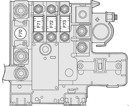
Fuse box near the battery
Alfa Romeo 159 -near the battery
№
A
Function
1
60
Instrument panel control unit
2
40
60*
Climate control system fan (1.8 140 HP versions)
Climate control system fan (2.2 JTS Selespeed versions)*
3
20
Electric steering lock
4
40
Brake branch point (pump)
5
40
20*
Brake branch point (solenoid valve) (ABS version)
Brake branch point (solenoid valve) (VDC version)*