| No. |
A |
Circuits Protected |
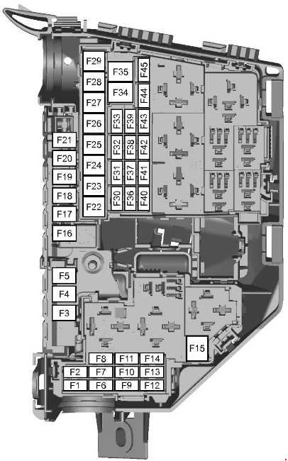
| F1 |
10 |
Transmission control module (AWF21) |
| 15 |
Transmission control module (MPS6) |
| F2 |
5 |
Glow plug monitoring (diesel engines) |
| 5 |
Vaporizer glow plug monitoring (2.0L Duratorq-TDCi Stage V and 2.2L Duratorq-TDCi Stage V) |
| F3 |
70 |
Engine cooling fan – twin fan (2.3L Duratec-HE and 2.2L Duratorq-TDCi automatic) |
| 80 |
Electric hydraulic power steering (EHPAS) (1.6L EcoBoost SCTi, 2.0L EcoBoost SCTi, 1.6L Duratorq-TDCi Stage V and 2.0L Duratorq-TDCi) |
| F4 |
60 |
Glow plugs |
| F5 |
60 |
Engine cooling fan (1.6L Duratorq-TDCi, 2.0L Duratorq-TDCi, 2.0L Duratorq-TDCi Stage V, 2.2L Duratorq-TDCi manual, 2.0L Duratec-HE, 2.3L Duratec-HE and 2.0L EcoBoost SCTi) |
| 70 |
Engine cooling fan – twin fan (1.6L EcoBoost SCTi) |
| F6 |
7.5 |
HEGO sensor (1.6L Duratorq-TDCi) |
| 10 |
HEGO sensor, CMS Sensor, Oxygen Sensor (engine management) |
| 20 |
Vaporizer glow plug (2.0L Duratorq-TDCi Stage V and 2.2L Duratorq-TDCi Stage V) |
| F7 |
5 |
Relay coils |
| F8 |
10 |
Powertrain control module, fuel metering unit, MAF sensor, fuel rail pressure control valve (engine management) |
| 20 |
Powertrain control module (2.0L EcoBoost SCTi and 2.0L Duratorq-TDCi Stage V) |
| 15 |
Powertrain control module (1.6L EcoBoost SCTi, 1.6L Duratorq-TDCi and 2.2L Duratorq-TDCi Stage V) |
| F9 |
10 |
MAF Sensor, Fuel Injectors (engine management) |
| 5 |
Fuel pump Vaporizer (2.0L Duratorq-TDCi Stage V) |
| 7.5 |
MAF Sensor, EGR bypass Valve, Fuel pump Vaporizer (2.2L Duratorq-TDCi Stage V) (engine management) |
| 7.5 |
Degas valve, TMAF sensor, active grille shutter, bypass valve, relay coil, auxiliary run on water pump (1.6L EcoBoost SCTi) |
| F10 |
10 |
Engine control module (2.0L Duratorq-TDCi) |
| 7.5 |
Auxiliary run on, water pump (1.6L EcoBoost SCTi) |
| F11 |
10 |
PCV Valve, VCV Valve, Water in Fuel Sensor, Sonic Purge Valve, Swirl Control Valve, Variable Intake Valve, EGR Valve, IVVT Oil Control Valve (engine management). T.MAF sensor, variable exhaust timing valve, active grille shutter, cannister purge valve, turbo control valve, wastegate valve (engine management). |
| 10 |
Turbo control valve, MAF sensor, active grille shutter, EGR valve, VCV valve (1.6L Duratorq-TDCi) |
| 5 |
MAF sensor, water in fuel sensor, active grille shutter, inlet metering valve (2.0L Duratorq-TDCi Stage V) |
| 7.5 |
Fuel rail pressure, fuel metering unit, active grille shutter (2.2L Duratorq-TDCi Stage V) |
| 10 |
Turbo control valve, variable intake timing valve, variable exhaust timing valve, cannister purge valve, electrical bypass valve (1.6L EcoBoost SCTi) |
| F12 |
10 |
Coil on Plug; Canister Purge Valve, Power Steering Pressure Switch (engine management) |
| 10 |
EGR throttle, variable turbo control (2.0L Duratorq-TDCi) |
| 5 |
Relay coils (2.0L Duratorq-TDCi Stage V, 2.2L Duratorq-TDCi Stage V and 1.5L Duratorq-TDCi) |
| 15 |
Ignition coils (1.6L EcoBoost SCTi and 2.0L EcoBoost SCTi) |
| F13 |
15 |
Air conditioning |
| F14 |
15 |
Diesel filter heater (2.0L Duratorq-TDCi, 2.0L Duratorq-TDCi Stage V and 1.6L Duratorq-TDCi) |
| 10 |
F1EGO sensors (2.2L Duratorq-TDCi Stage V) |
| F15 |
40 |
Starter relay |
| F16 |
80 |
Diesel auxiliary heater (PTC) |
| F17 |
60 |
Central fuse box supply A |
| F18 |
60 |
Central fuse box supply B |
| F19 |
60 |
Rear fuse box supply C |
| F20 |
60 |
Rear fuse box supply D |
| F21 |
30 |
VQM/non VQM: Cluster/Audio/AC/FLR |
| F22 |
30 |
Windscreen wiper module |
| F23 |
30 |
2006-2008: Heated rear window |
| 25 |
2009-2015: Heated rear window |
| F24 |
30 |
Headlamp washer |
| F25 |
30 |
ABS valves |
| F26 |
40 |
ABS pump |
| F27 |
30 |
2006-2010: Fuel fired heater |
| 25 |
2011-2015: Fuel fired heater |
| F28 |
40 |
Heater blower |
| F29 |
– |
Not used |
| F30 |
5 |
2011-2015: ABS 30 feed |
| F31 |
15 |
Horn |
| F32 |
5 |
2009-2015: Fuel fired heater – remote control |
| F33 |
5 |
Light switch module, engine compartment fuse box coils |
| F34 |
40 |
Heated windscreen (left-hand side) |
| F35 |
40 |
Heated windscreen (right-hand side) |
| F36 |
5 |
2006-2010: ABS |
| 15 |
2011-2015: Rear wiper 15 feed |
| F37 |
10 |
2006-2010: Heated front washer jets |
| 7.5 |
2011-2015: Heated front washer jets/FLR + FSM KL15 |
| F38 |
5 |
2006-2010: Adaptive Cruise Control (ACC) |
| 10 |
2011-2015: PCM/TCM/EHPAS15 feed |
| F39 |
15 |
Adaptive front lighting system (AFS) |
| F40 |
5 |
2011-2015: Headlamp leveling/AFS module |
| F41 |
20 |
Instrument panel |
| F42 |
10 |
2006-2010: Engine control module, transmission control module, electric hydraulic power steering (EHPAS) |
| 5 |
2011-2015: Cluster IP |
| F43 |
5 |
2006-2010: Headlamp levelling, adaptive front lighting system (AFS) |
| 15 |
2011-2015: Audio/BVC module/DAB module |
| F44 |
20 |
Electric hydraulic power steering module (2.0L Duratorq-TDCi), vacuum pump (2.5L Duratec-ST) |
| 5 |
2011-2015: Automatic AC/Manual AC |
| F45 |
5 |
2006-2010: Rear window wiper |
| 15 |
2011-2015: FLR (Start Stop) |