Toyota Land Cruiser 70 (AU 76/78/79; 2009 – 2014) – fuse and relay box diagram
Year of production: 2009, 2010, 2011, 2012, 2013, 2014
This article provides fuse box diagrams for the Toyota Land Cruiser 76/78/79 (Australia) from the years 2009 to 2014. It also includes details on the location of the fuse panels inside the vehicle and explains the function and layout of each fuse.
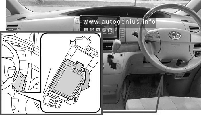
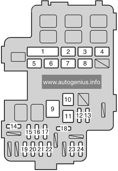
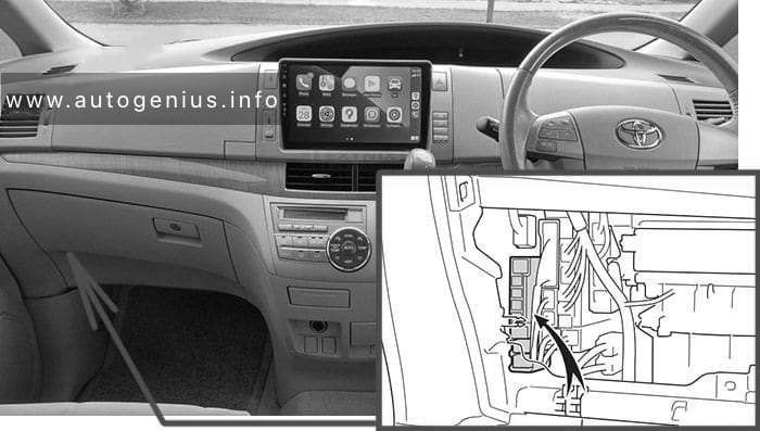
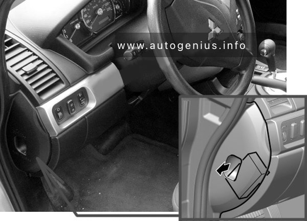
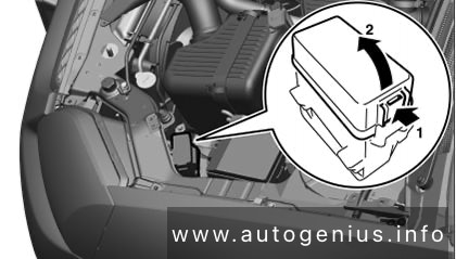
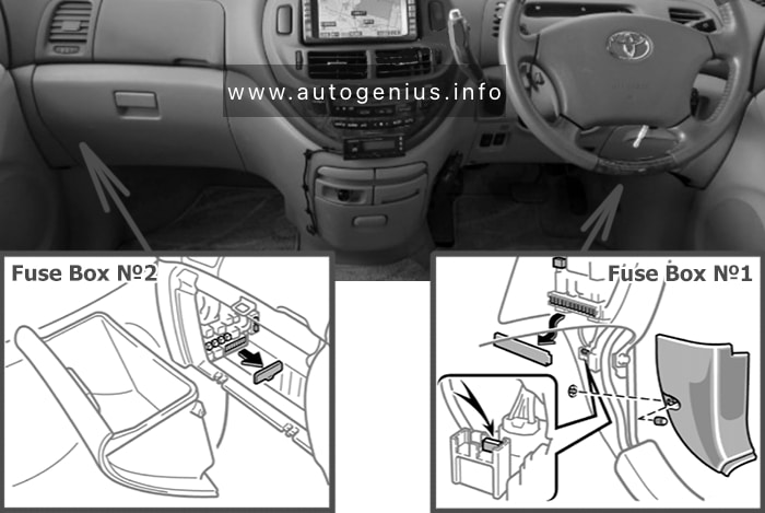
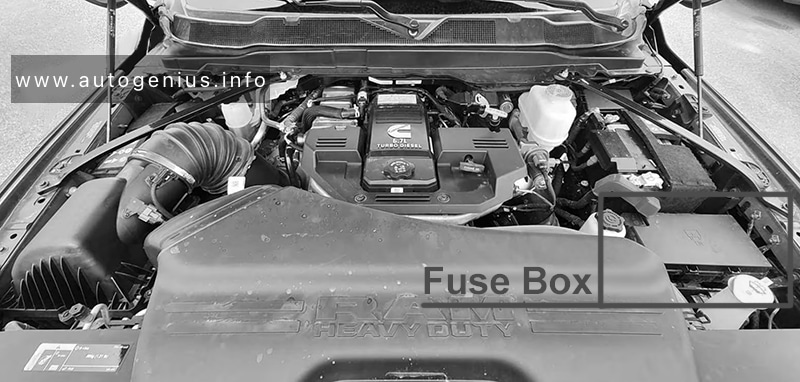
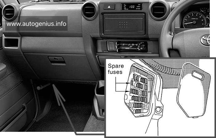
Passenger Compartment Fuse Box
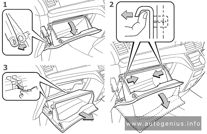
Fuse Box Location
Remove the lid to access.
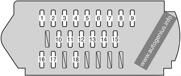
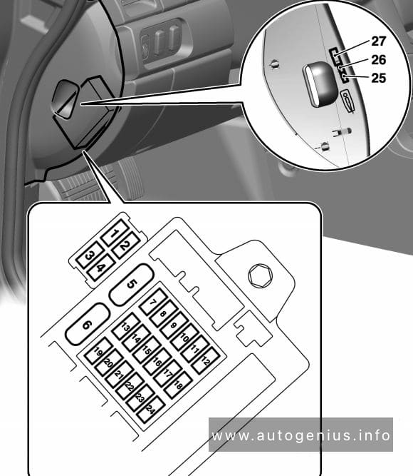
Fuse Box Diagrams
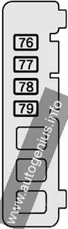
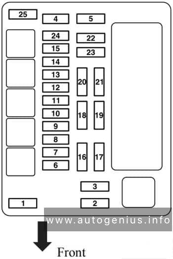
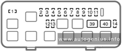
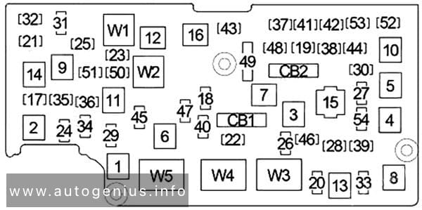
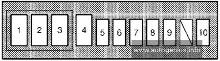
Fuse Box №1
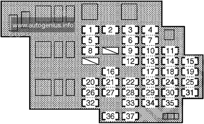
Assignment of the fuses under the instrument panel
| № | Name | Amp | Description |
|---|---|---|---|
| 1 | DIFF | 30A | Differential lock system |
| 2 | DOOR | 30A | Power door lock system / wireless remote control system |
| 3 | POWER | 30A | Power windows |
| 4 | TRAILER | 30A | Trailer lights (tail lights), turn signal lights |
| 5 | ECU IG | 15A | 2009-2012: Electronically controlled fuel injection pump system, charging system, engine glow system, four-wheel drive control system, windshield wipers and washer, power antenna, differential lock system 2012-2014: Electronically controlled fuel injection pump system, charging system, engine glow system, four-wheel drive control system, windshield wipers and washer, power antenna, differential lock system, ABS, wireless remote control system |
| 6 | WIP | 20A | Windshield wipers and washer |
| 7 | CIG | 15A | Cigarette lighter |
| 8 | GAUGE | 15A | Back-up lights, air conditioning system, rear window defogger, electronically controlled fuel injection pump system, clock, emergency flashers |
| 9 | FUEL HTR | 15A | Fuel heater |
| 10 | ACC | 7.5A | Clock, audio system, power antenna |
| 11 | STOP | 15A | Electronically controlled fuel injection pump system, stop lights, high mounted stoplight |
| 12 | DC/DC | 15A | DC/DC converter |
| 13 | H/LP HI LH | 10A | No circuit |
| 14 | TRAILER STOP | 15A | Trailer lights (tail lights) |
| 15 | PANEL | 10A | Clock, audio system, emergency flashers, instrument panel light control, door lock system, rear window defogger, power antenna, gauges and meters, air conditioning system |
| 16 | DOME №1 | 10A | 2009-2012: Gauges and meters, interior light 2012-2014: Gauges and meters, interior light, wireless remote control system |
| 17 | H/LP HI RH | 10A | Right-hand headlight (high beam), service reminder indicators and warning buzzers |
| 18 | OBD2 | 7.5A | On-board diagnosis system |
| 19 | TAIL | 10A | Parking lights, tail lights, license plate lights, electronically controlled fuel injection pump system, trailer lights (tail lights) |
| 20 | FR FOG | 15A | Front fog lights, gauges and meters |
| 21 | ECU-B | 10A | Electronically controlled fuel injection pump system, clock, power antenna |
| 22 | INJ | 10A | Electronically controlled fuel injection pump system |
| 23 | H/LP LO LH | 10A | Left-hand headlight (low beam) |
| 24 | STOP | 30A | All components in “STOP” and “TRAILER STOP” fuses |
| 25 | DOME №2 | 10A | Interior lights |
| 26 | RR FOG | 15A | No circuit |
| 27 | RADIO | 15A | Audio system |
| 28 | IGN | 10A | Electronically controlled fuel injection pump system, SRS airbag system |
| 29 | H/LP LO RH | 10A | Right-hand headlight (low beam) |
| 30 | DEFOG | 20A | Electronically controlled fuel injection pump system, rear window defogger |
| 31 | EFI №2 | 10A | Electronically controlled fuel injection pump system |
| 32 | A/C | 10A | Air conditioning system |
| 33 | MET | 10A | Gauges and meters |
| 34 | ST | 7.5A | Electronically controlled fuel injection pump system, starting system, engine glow system |
| 35 | BLACK | 7.5A | No circuit |
| 36 | SPARE | 10A | Spare fuse |
| 37 | SPARE | 20A | Spare fuse |
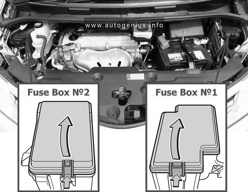
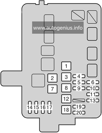
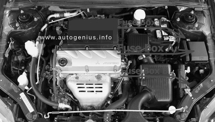
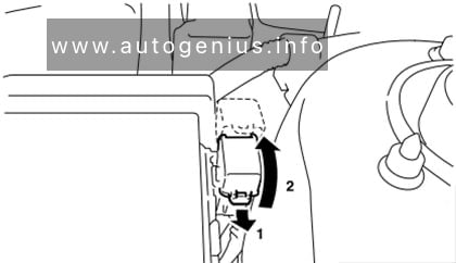
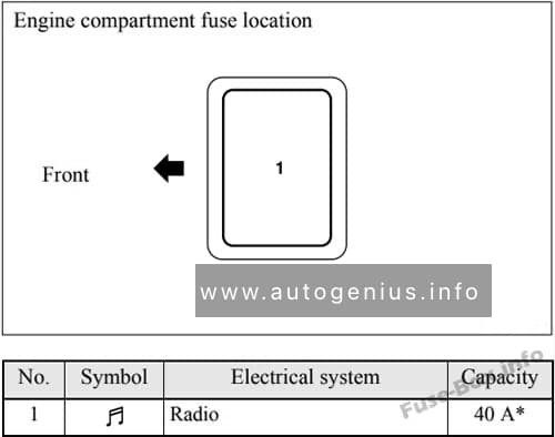
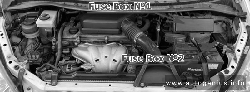
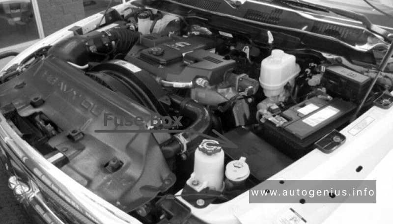
Engine Compartment Fuse Boxes
Fuse Box Location
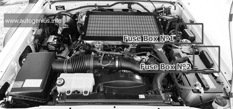
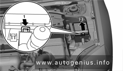
Fuse Box Diagrams
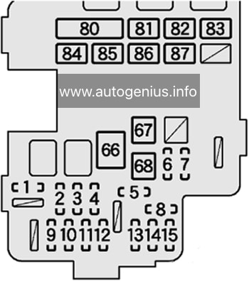
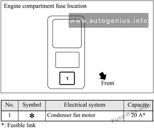
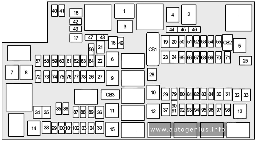
Fuse Box №1
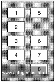
Assignment of the fuses in the Fuse Box №1
| № | Name | Amp | Description |
|---|---|---|---|
| 1 | HTR | 50A | Air conditioning system |
| 2 | ALT | 140A | All components in “GLOW1”, “GLOW2”, “HEAD”, “MAIN1 ”, “MAIN2”, “AM2”, “HORN”, “EFI MAIN”, “EFI MAIN2”, “TURN&HAZ”, “ALT-S”, “H/LP LO RH”, “H/LP LO LH”, “TRAILER”, “H/LP HI RH”, “TAIL”, “PANEL”, “FR FOG”, “DOME”, “ECU-B”, “RADIO” and “DOOR” fuses |
| 3 | GLOW1 | 80A | Engine glow system |
| 4 | GLOW2 | 80A | Engine glow system |
| 5 | AM1 №2 | 50A | 2009-2012: All components in “ECU IG”, “GAUGE” and “WIP” fuses 2012-2014: All components in “ECU IG”, “GAUGE” and “WIP” fuses, front fog lights, rear fog lights |
| 6 | AM1 | 30A | Cigarette lighter, starting system, all components in “ST” and “ACC” fuses |
| 7 | AM1 №3 | 50A | Cigarette lighter, all components in “ACC” fuse |
| 8 | ALT MAIN | 50A | Stop lights, air conditioning system, on-board diagnosis system, audio system |
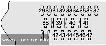
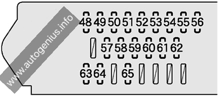
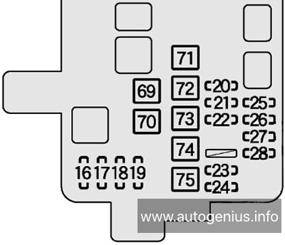
Fuse Box №2
Assignment of the fuses in the Fuse Box №2
| № | Name | Amp | Description |
|---|---|---|---|
| 1 | HEAD | 50A | Right-hand headlight (low beam), left-hand headlight (low beam), right-hand headlight (high beam), left-hand headlight (high beam) |
| 2 | MAIN2 | 50A | 2009-2012: Audio system, all components in “ECU-B”, “DOME №1”, “DOME №2” and “DOOR” fuses |
| ABS MTR | 50A | 2012-2014: ABS | |
| 3 | MAIN1 | 50A | 2009-2012: Tail lights, front fog lights, rear fog lights, all components in “PANEL” fuse 2012-2014: Tail lights, all components in “PANEL” fuse, trailer, audio system, all components in “ECU-B”, “DOME №1” and “DOOR” fuses |
| 4 | AM2 | 50A | All components in “MET”, “IGN” and “INJ” fuses |
| 5 | HORN | 10A | Horns |
| 6 | EFI MAIN | 15A | Electronically controlled fuel injection pump system |
| 7 | EFI MAIN2 | 15A | Electronically controlled fuel injection pump system |
| 8 | TURN&HAZ | 15A | Turn signal lights, tail lights, service reminder indicators and warning buzzers, trailer lights (tail lights) |
| 9 | ABS SOL | 30A | 2012-2014: ABS |
| 10 | ALT-S | 7.5A | Charging system |
WARNING: Terminal and harness assignments for individual connectors will vary depending on vehicle equipment level, model, and market.