Cadillac Escalade (2021 – 2022) – fuse and relay box diagram
Year of production: 2021, 2022
The 2021-2022 Cadillac Escalade represents a significant evolution for the luxury full-size SUV. The redesign of the Escalade introduced a more refined look, modernized technology, and advanced driving dynamics, making it a standout in the premium SUV segment.
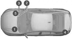
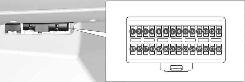
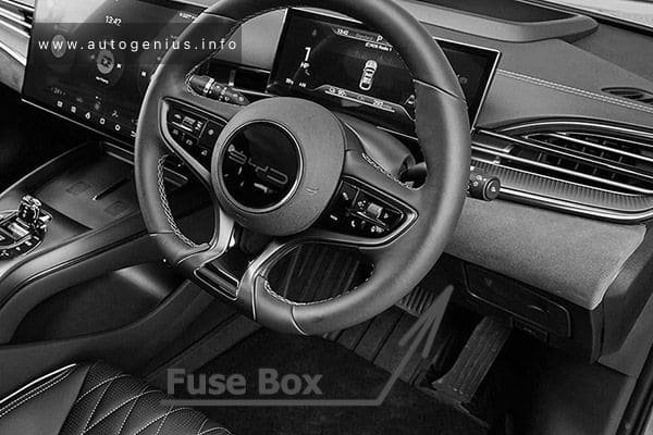
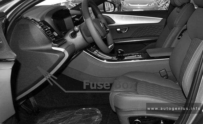
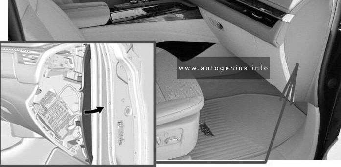
Instrument Panel
Fuse Box Location
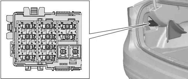
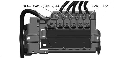
There are relays on the back of the fuse block. To access, press the tabs and remove the fuse block.
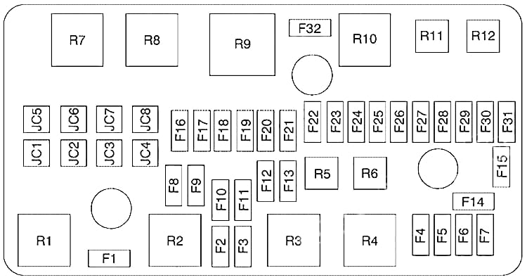
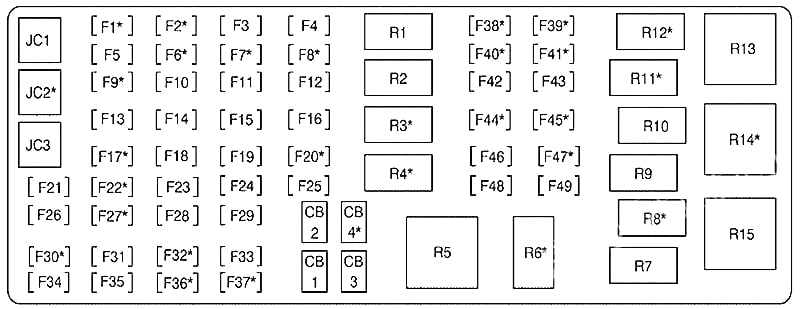
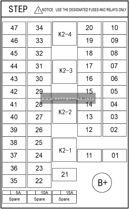
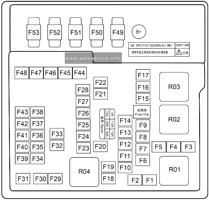
Fuse Box Diagram
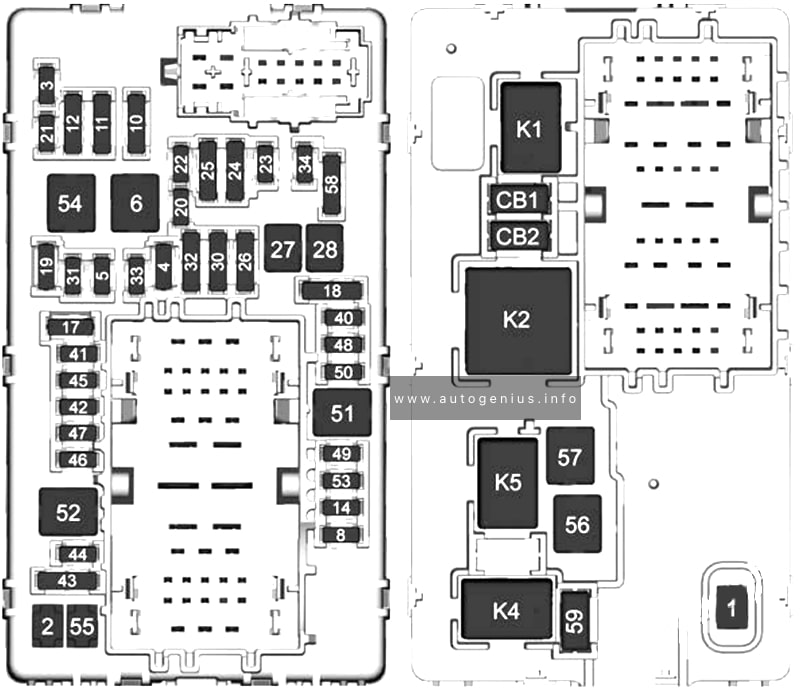
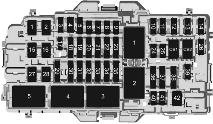
Assignment of the fuses in the Instrument Panel Fuse Box
| № | Usage |
|---|---|
| F1 | Right Door |
| F2 | Left Door |
| F3 | Universal Garage Door Opener (UGDO)/ OnStar Hands-free Calling (OHC)/ Camera |
| F4 | Body Control Module 2 |
| F5 | Displays |
| F6 | Front Blower |
| F8 | Left Door Panel |
| F10 | Tilt/Column Lock |
| F11 | Data Link Connector/ Column Lock/ Integrated Center Stack/ USB |
| F12 | Central Gateway Module (CGM)/ Onstar |
| F14 | Right Door Panel |
| FI 7 | Steering Wheel Control |
| F18 | 2021: AVM1 |
| F19 | — |
| F20 | — |
| F21 | — |
| F22 | Heated Wheel |
| F23 | — |
| F24 | — |
| F25 | Special Equipment Option (SEO)/UPFITTER |
| F26 | USB/ Special Equipment Option(SEO) Retained Accessory Power (RAP) |
| F27 | Auxiliary Power Outlet (APO)/ Retained Accessory Power |
| F28 | — |
| F30 | Sensing and Diagnostic Module/ Automatic Occupant Sensing/ Driver Monitor System/ Night Vision Module |
| F31 | Body Control Module 3 |
| F32 | Center Stack Module (CSM)/ USB |
| F33 | Body Control Module 4 |
| F34 | Out of Park |
| F40 | — |
| F41 | — |
| F42 | Electric Park Brake Switch |
| F43 | Rear Seat Infotainment/Multi-Functional Control |
| F44 | 2021: AVM1 |
| F45 | Radio Module |
| F46 | 2021: Body Control Module 1A |
| F47 | — |
| F48 | Telematics Control Module |
| F49 | Body Control Module 1 |
| F50 | 2021: DMS |
| F51 | — |
| F52 | — |
| F53 | — |
| F54 | Sunroof |
| F55 | Auxiliary Power Outlet 3 |
| F56 | Direct Current/Direct Current Converter Battery 1 |
| F57 | Direct Current/Direct Current Converter Battery 2 |
| F58 | Spare |
| F59 | — |
| Circuit Breakers | |
| CB01 | Auxiliary Power Outlet 1 |
| CB02 | Auxiliary Power Outlet 2 |
| Relays | |
| K1 | — |
| K2 | Retain Accessory Power/ Accessory 1 |
| K4 | Retain Accessory Power/ Accessory 2 |
| K5 | — |
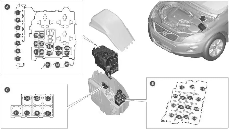
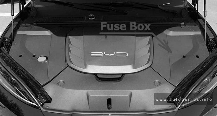
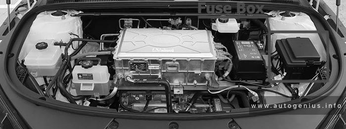
Engine Compartment
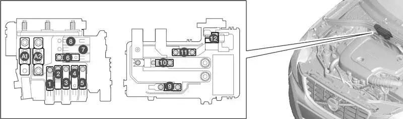
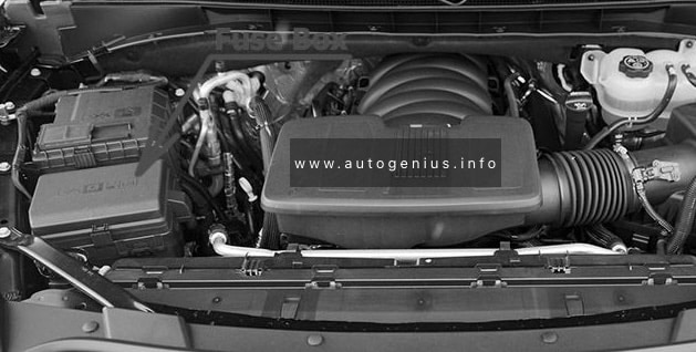
Fuse Box Location
The engine compartment fuse block is in the engine compartment, on the driver side of the vehicle.
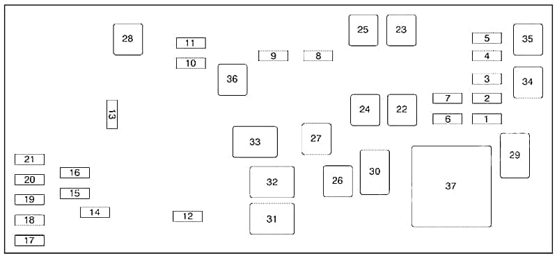
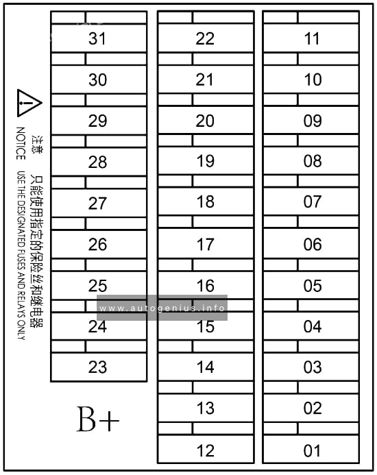
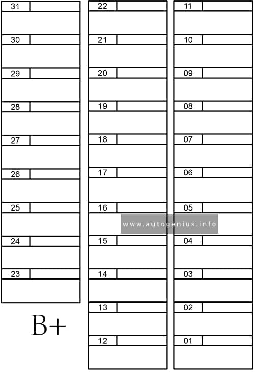
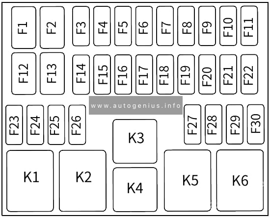
Fuse Box Diagram
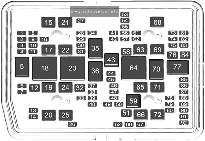
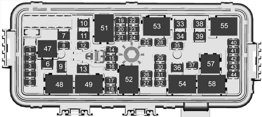
Assignment of the fuses in the engine compartment
| № | Usage |
|---|---|
| 1 | — |
| 2 | — |
| 3 | — |
| 4 | — |
| 6 | Exterior Lighting Module 7 |
| 7 | Exterior Lighting Module 4 |
| 8 | — |
| 9 | Exterior Lighting Module 5 |
| 10 | Exterior Lighting Module 6 |
| 11 | Long Range Radar/ Front Short Range Radar |
| 12 | — |
| 13 | Washer Front |
| 14 | Washer Rear |
| 15 | Rear Electrical Center 2 |
| 16 | Power Sounder |
| 17 | 2022: Electronic Brake Control Module Battery 1 |
| 19 | DC/AC Inverter |
| 20 | Instrument Electrical Center Right 2 |
| 21 | — |
| 22 | Instrument Electrical Center Left 1 |
| 24 | 2021: EBCM 2022: Fuel Heater |
| 25 | Rear Electrical Center 1 |
| 26 | Camera Wash |
| 27 | Horn |
| 28 | Headlamp – Right |
| 29 | Headlamp – Left |
| 30 | Exterior Lighting Module 3 |
| 31 | Exterior Lighting Module 1 |
| 32 | — |
| 33 | Not R/C |
| 34 | — |
| 37 | MISC (Body Ignition 1) |
| 38 | MISC (Body Ignition 2) |
| 39 | Upfitter |
| 40 | MISC (Instrument Panel (IP)) |
| 41 | Trailer Parking Lamps |
| 42 | Right Taillamp |
| 44 | Trailer Tow |
| 45 | Secondary Axle Motor |
| 46 | Engine Control Module (ECM) Ignition |
| 47 | OBD Engine |
| 48 | — |
| 49 | Transmission Auxiliary Oil Pump |
| 50 | A/C Clutch |
| 51 | Transfer Case Control Module |
| 52 | Front Wiper |
| 53 | — |
| 54 | Left Taillamps |
| 55 | Trailer Back-up Lamp |
| 56 | Semi Active Damping System |
| 57 | Spare |
| 58 | Starter Motor |
| 60 | 2021: Active Fuel Management 1 2022: Powertrain Sensor 2 |
| 61 | Automatic Lamp Control (ALC) Main |
| 62 | Integrated Chassis Control Module/ Canister Vent Solenoid/ Diesel Exhaust Fluid |
| 63 | Trailer Brake |
| 65 | 2021: AUX UEC |
| 66 | Left Cool Fan Motor |
| 67 | Active Fuel Management 2 |
| 68 | Automatic Lamp Control (ALC) Motor |
| 69 | Starter Pinion |
| 71 | Cool Fan Motor Lower |
| 72 | Right Cool Fan Motor/Lower |
| 73 | Left Trailer Stop Turn Lamp |
| 74 | Trailer Interface Module 2 |
| 75 | Diesel Exhaust Fluid Controller |
| 76 | Electric Power Running Boards |
| 78 | Engine Control Module |
| 79 | 2022: Cabin Cool Pump 17W |
| 80 | 2022: Cabin cool pump 17W 2022: Powertrain Sensor 1 |
| 81 | Right Trailer Stop Turn Lamp |
| 82 | Trailer Interface Module 1 |
| 83 | Fuel Tank Zone Module |
| 84 | Trailer Battery |
| 85 | 2021: Engine 2022: Auxiliary Water Pump |
| 86 | Engine Control Module |
| 87 | Injector B Even |
| 88 | O2 B Sensor |
| 89 | O2 A Sensor |
| 90 | Injector A Odd |
| 91 | Engine Control Module (ECM) Throttle Control |
| 92 | Cool Fan Clutch AERO Shutter |
| Relays | |
| 5 | — |
| 18 | DC/AC Inverter |
| 23 | 2022: Fuel Heater |
| 35 | Trailer Park Lamp |
| 36 | Run/Crank |
| 43 | Secondary Axle Motor |
| 59 | A/C Clutch |
| 64 | Starter Motor |
| 70 | Starter Pinion |
| 77 | Powertrain |
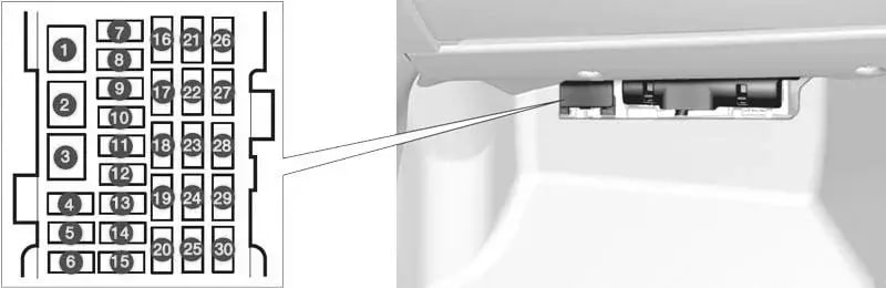
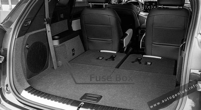
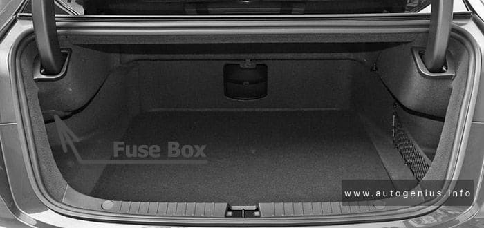
Luggage Compartment
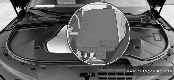
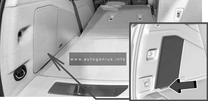
Fuse Box Location
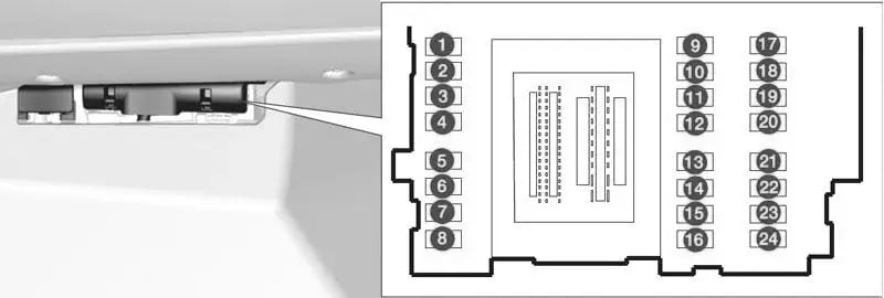
The rear compartment fuse block is behind the access panel on the left side of the compartment. Pull the panel out by grabbing the finger access slot at the rear edge.
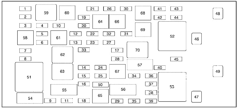
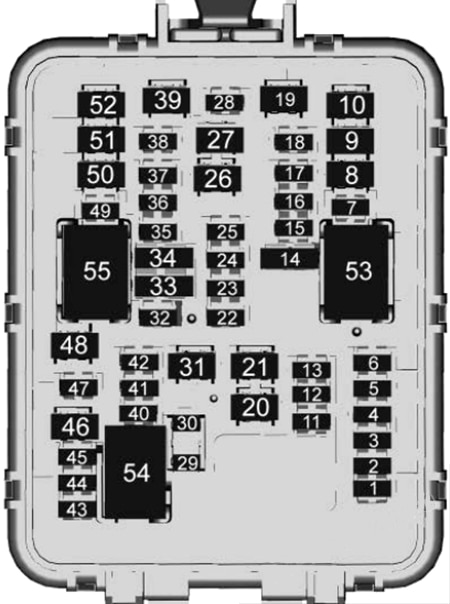
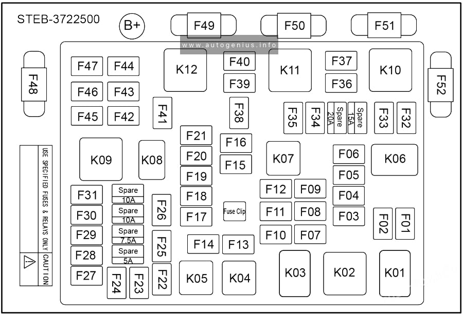
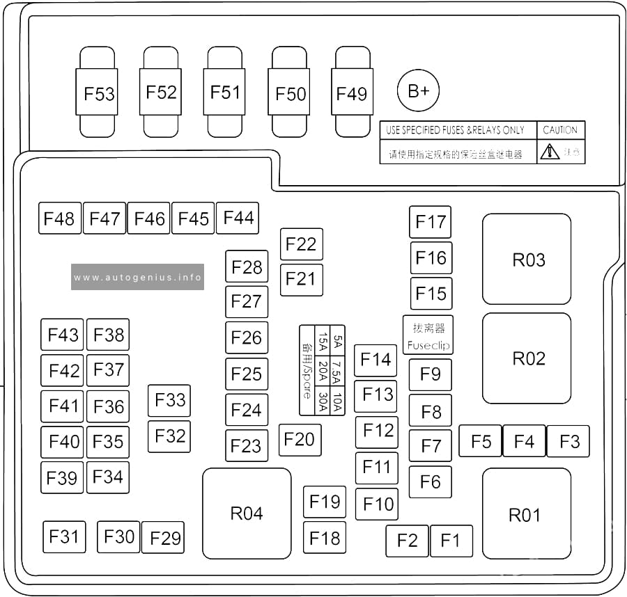
Fuse Box Diagram
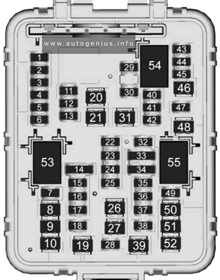
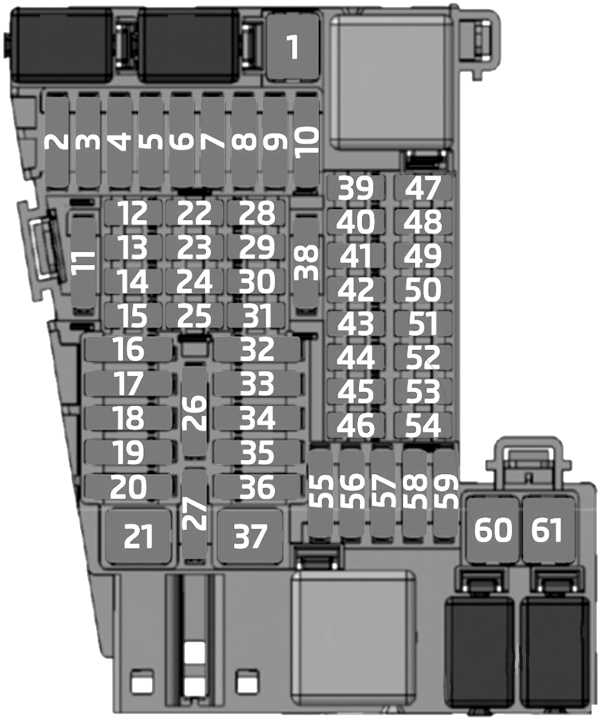
Assignment of the fuses in the luggage compartment
| № | Usage |
|---|---|
| F01 | Remote Function Actuator |
| F02 | Wireless Charging Module |
| F03 | Heated Seat Module Row 1 (Battery 1) |
| F04 | Memory Seat Module (MSM) Driver |
| F05 | — |
| F06 | — |
| F07 | Amplifier Auxiliary 2 |
| F08 | — |
| F09 | Special Equipment Upfitter 2 |
| F10 | Motor Seatbelt Passenger |
| F1 | Power Folding Seat Row 2 |
| F12 | Glass Breakage Sensor |
| F13 | — |
| F14 | — |
| F15 | Heated Seat Module Row 1 (Battery 2) |
| F16 | Right Hand Cinch Latch |
| F17 | Memory Seat Module Passenger |
| F18 | Rear Wiper |
| F19 | Motor Seatbelt Driver |
| F20 | Rear Defogger |
| F21 | — |
| F22 | Rear HVAC Display Control |
| F23 | External Object Calculation Module |
| F24 | Amplifier Auxiliary 3 |
| F25 | Obstacle Detection |
| F26 | Rear Drive Control Module |
| F27 | Amplifier Auxiliary 1 |
| F28 | Video Processing Module |
| F29 | — |
| F30 | — |
| F31 | Amplifier |
| F32 | — |
| F33 | Integrated Chassis Control Module |
| F34 | Heated Seat Module Row 2 |
| F35 | Hands Free Closure Release |
| F36 | Exterior Lighting Module |
| F37 | — |
| F38 | Power Slide Console |
| F39 | — |
| F40 | — |
| F41 | — |
| F42 | — |
| F43 | Universal Park Assist |
| F44 | — |
| F45 | Adaptive Forward Lighting/ Automatic Headlamp Leveling |
| F46 | Rear HVAC Blower Motor |
| F47 | Left Hand Cinch Latch |
| F48 | Power Seat Recline Module |
| F49 | Lift Glass |
| F50 | Driver Power Seat |
| F51 | Power Liftgate Module |
| F52 | Passenger Power Seat |
| Relays | |
| K53 | — |
| K54 | — |
| K55 | Lift Glass |
WARNING: Terminal and harness assignments for individual connectors will vary depending on vehicle equipment level, model, and market.