Ford F-350 (1992 – 1997) – fuse and relay box diagram
Year of production: 1992, 1993, 1993, 1994, 1995, 1996, 1997
This article focuses on the ninth-generation Ford F-Series, produced from 1992 to 1997. It provides fuse box diagrams for the 1992, 1993, 1994, 1995, 1996, and 1997 Ford F-150, F-250, and F-350 models, along with information on the locations of the fuse panels within the vehicle and the assignment of each fuse and relay (fuse layout).
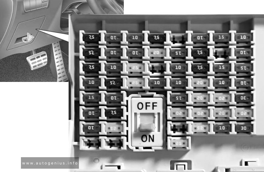
Passenger Compartment Fuse Panel
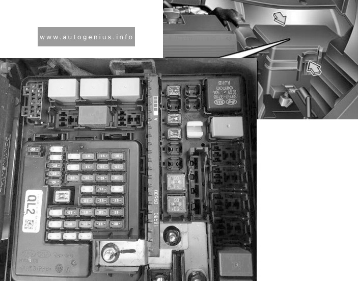
Fuse box location
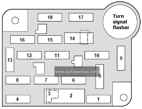
The fuse panel is located behind the cover to the left of the steering wheel. Remove the cover from the lower edge of the instrument panel by pulling on handle to disengage the fasteners.
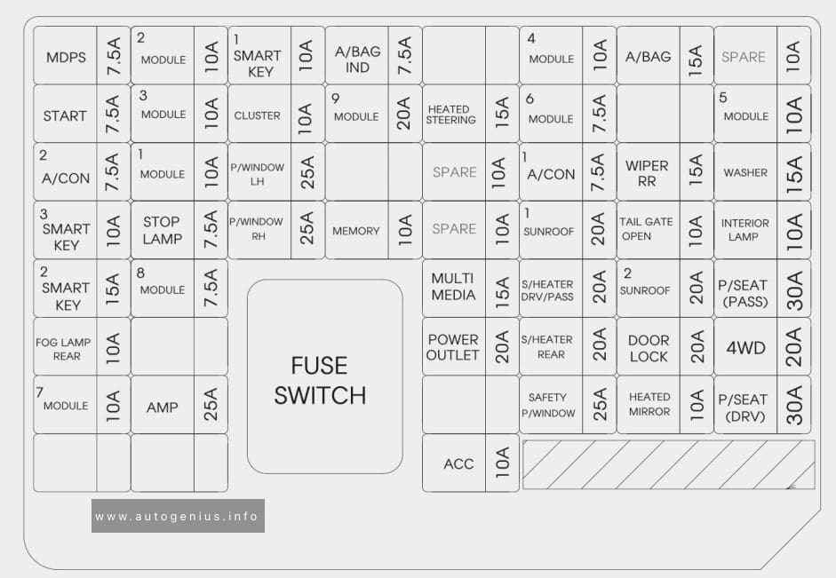
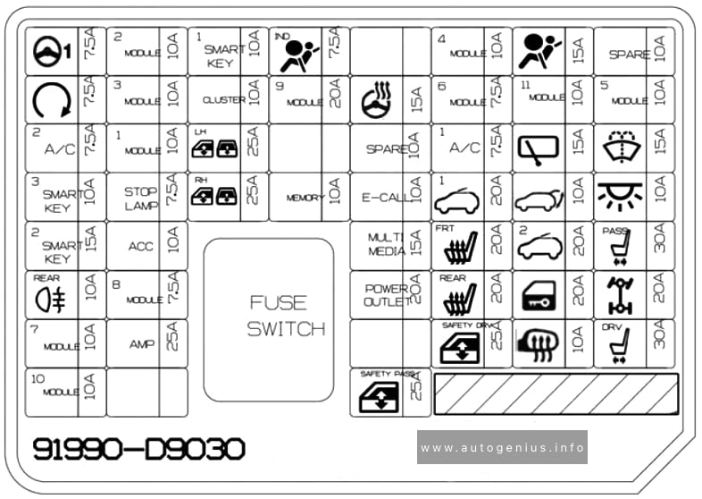
Fuse box diagram

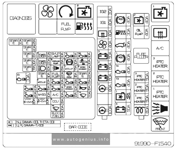
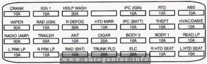
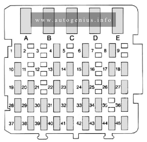
Assignment of the fuses in the instrument panel
| № | A | Description |
| 1 | 30 | Heater/Air conditioner blower |
| 2 | 30 | Wiper/Washer |
| 8.25 | Circuit breaker: Interval Wiper/Washer | |
| 3 | 3 | Idle position switch (Diesel) |
| 4 | 15 | Exterior lamps; Instrument illumination; Trailer exterior lamp relay; Warning buzzer/chime module |
| 5 | 10 | Airbag restraint |
| 6 | 15 | Fuel Tank Selector (Diesel Only), Air Conditioner/Heater, Remote/Keyless Entry |
| 7 | 15 | Turn Lamps |
| 8 | 15 | Courtesy Lamps. Engine Compartment Lamp, Radio Memory, Power Mirrors, Clock Memory, Speedometer Memory, Warning Chime, Sun Visor Mirror Illumination, Keyless Entry |
| 9 | 15 | Power point |
| 25 | Power point | |
| 10 | 4 | Instrument illumination |
| 11 | 15 | Radio, Radio Display Dimmer |
| 12 | 20 | Circuit breaker: Electronic Shift Motor 4-wheel, Power Door Locks, Tailgate Power Window (Bronco) |
| 30 | Circuit breaker: Power Door Lock, Power Tailgate Window (Bronco), Electronic Shift Control, Power Lumbar | |
| 13 | 15 | Stop and Hazard Lamps, Stop Sense For: Anti-lock Brakes, Speed Control, Electronic Engine Control, Brake Shift Interlock, Anti-Lock Brakes |
| 14 | 20 | Circuit breaker: Power Windows, Tailgate Power Window: Instrument Panel Switch |
| 15 | 20 | Anti-Lock Brakes |
| 16 | 15 | Cigarette Lighter, Generic Scan Tool |
| 17 | 10 | Overdrive Switch. Stop Lamp Switch, Warning Chime, Diesel Warning Lamps Display, Fuel Water Switch, Low Vacuum Warning Switch, Instrument Cluster, Electronic Shift Control, Tachometer, Gauges, Electronic Transmission |
| 18 | 10 | Air Bag Restraint, Automatic Day/Night Mirror, Brake Shift Interlock, Electronic Shift Module 4-wheel Drive, Overhead Console, Speedometer, Speed Control. Electronic Shift Control |
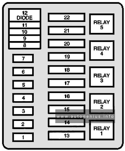
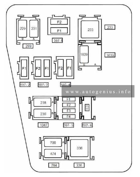
Engine compartment fuse box
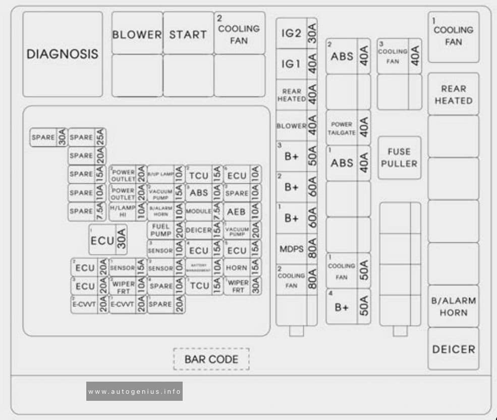
Fuse box diagram

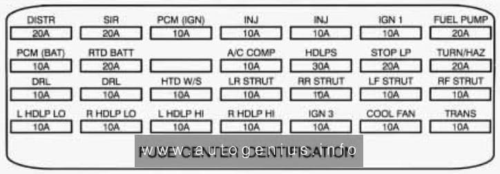
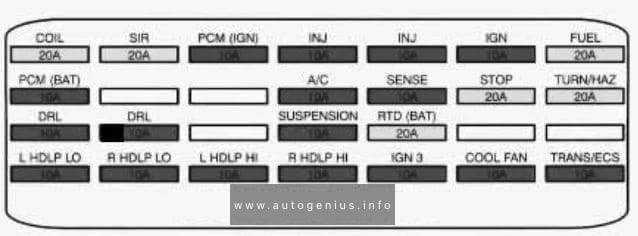
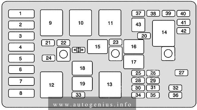
Assignment of the fuses in the engine compartment
| № | A | Description |
| 1 | 20A | Audio power |
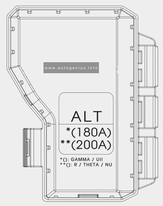
| 2 | (15A) | Fog lamps; 200A alternator (Diesel ambulance only) |
| 3 | 30A | Daytime running lamps (Canada only); Headlamp flash-to-pass; Horn |
| 4 | 25A | Trailer back-up lamps; Trailer running lamps |
| 5 | 15A | Back-up lamps; Daytime running lamp module (DRL) (Canada only); Oxygen sensor heater; Trailer battery charge relay |
| 6 | 10A | Trailer right-hand stop/turn lamp |
| 7 | 10A | Trailer left-hand stop/turn lamp |
| 8 | 30A maxi | Injector driver module |
| 9 | 30A (Gas) / 20A (Diesel) | Powertrain control system |
| 10 | 20A maxi | Instrument panel fuses: 15,18; Starter relay coil |
| 11 | — | Not used |
| 12 | Diode | Powertrain control system relay coil |
| 13 | 50A maxi | Instrument panel fuses: 5,9,13 |
| 14 | — | Not used |
| 15 | 50A maxi | Instrument panel fuses: 1, 7; Power distribution box: fuse 5 |
| 16 | 20A maxi | Fuel pump feed (Gas engine) |
| 17 | 50A maxi | Alternator charge lamp; Idle position switch (Diesel); Instrument panel fuses: 2, 6, 11,14,17; Power distribution box: fuse 22 |
| 18 | 30A maxi | Trailer battery charge |
| 19 | 40A maxi | Headlamps |
| 20 | 50A maxi | Instrument panel fuses: 4, 8, 12,16 |
| 21 | 30A maxi | Trailer brake feed |
| 22 | 20A maxi (Gas) / 30A (Diesel) | Distributor pickup (Gas engine); Fuel line heater (Diesel); Glow plug controller (Diesel); Ignition coil (Gas engine); Powertrain control system relay coil; Thick film integrated (TFI) module (Gas engine) |
| Relay 1 | Powertrain control system | |
| Relay 2 | Fuel pump (Gas engine); Injector driver module (IDM relay) (Diesel) |
|
| Relay 3 | Horn | |
| Relay 4 | Trailer tow lamps | |
| Relay 5 | Anti-lock brake system (ABS) pump motor |
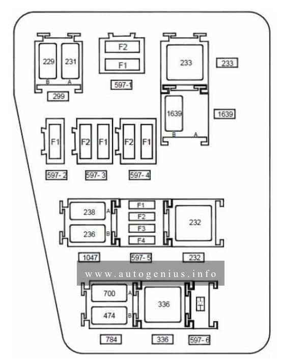
Trailer relay box
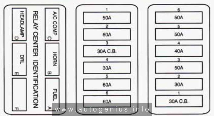
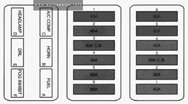
Fuse box diagram
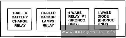
Assignment of the fuses in the trailer relay box
| Circuit Protected | Size | Location |
| Headlamps & High Beam Indicator | 22 Amp Circ. Brkr. | Integral with Headlamp Switch |
| Alternator, 95 Amp | 12 Ga. Fuse Link | At Starting Motor Relay (Gasoline Engine) |
| Alternator, 130 Amp | (2) 12 Ga. Fuse Links | At Starting Motor Relay (Diesel Engine) |
| Diesel Glow Plugs | (2) 14 Ga. Fuse Links | At Starting Motor Relay |
WARNING: Terminal and harness assignments for individual connectors will vary depending on vehicle equipment level, model, and market.