Toyota Highlander Hybrid (XU40; 2009 – 2010) – fuse and relay box diagram
Year of production: 2009, 2010
The Toyota Highlander XU40 crossover represents the 2nd generation of the Toyota Highlander model range. Years of production: 2007, 2008, 2009, 2010, 2011, 2012, 2013, 2014. During this time, the model has been restyled. In our material you can find a description of fuses and relays Toyota Highlander 2 with box diagrams and their locations.
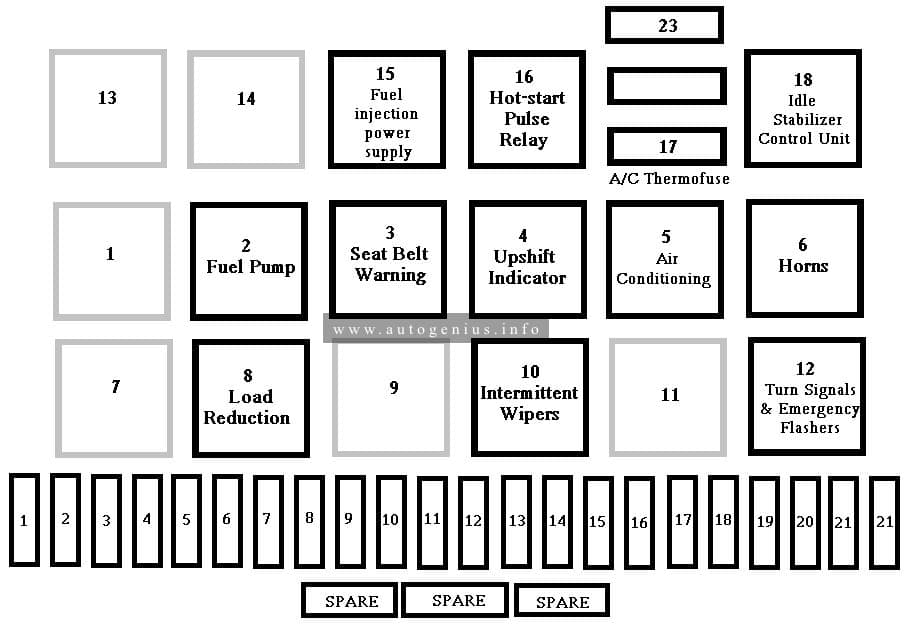
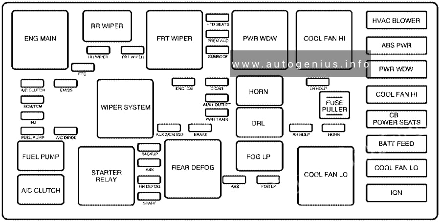
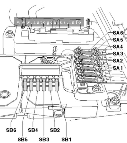
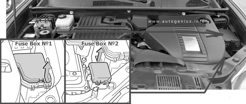
Engine compartment
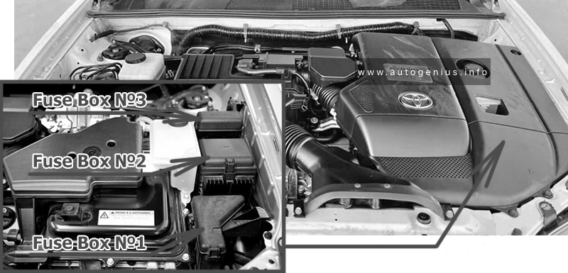
Fuse box location
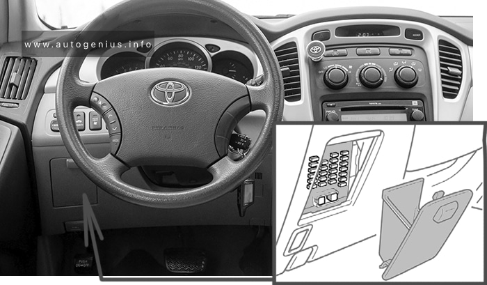
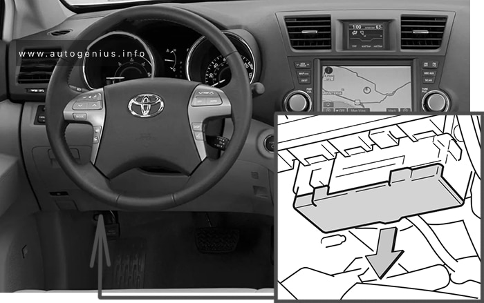
The fuse block is located under the instrument panel. Remove the lid to access
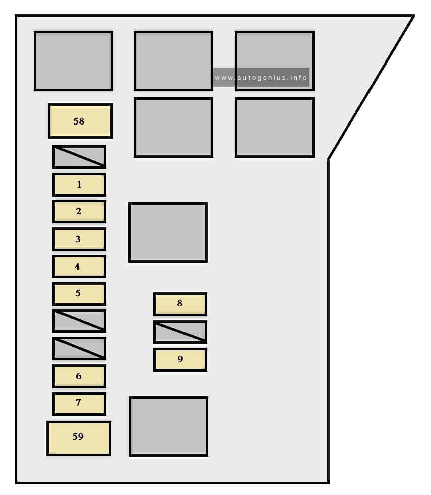
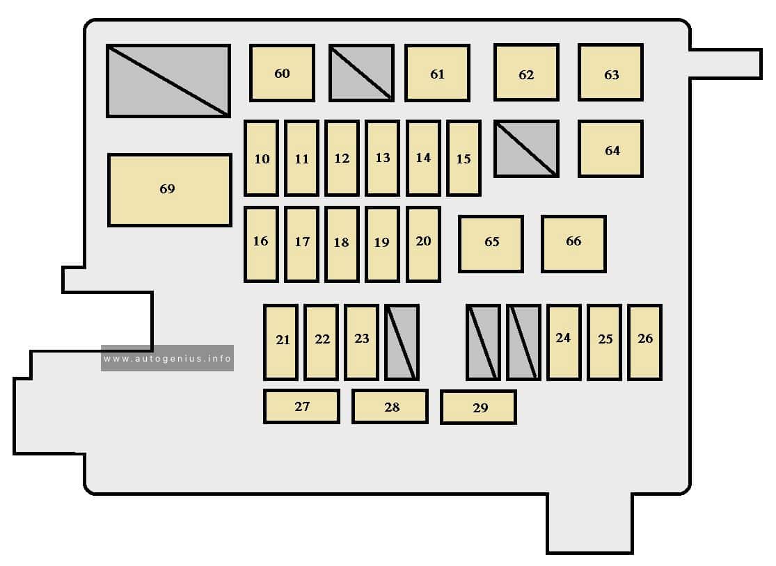
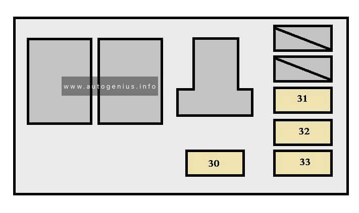
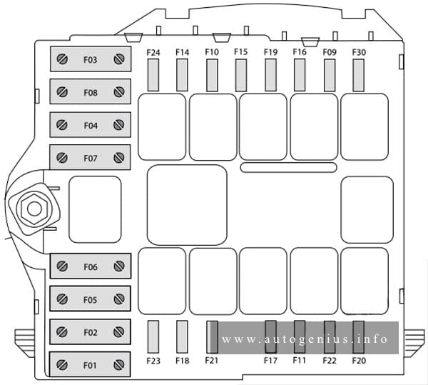
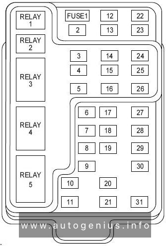
Fuse box diagram
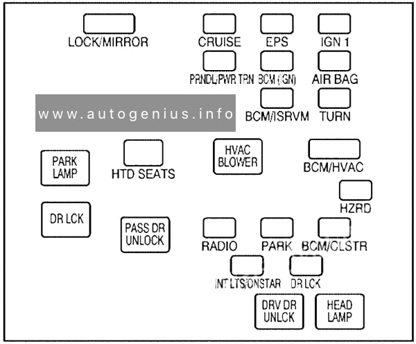
Type A (cover)
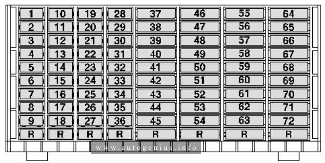
Type A (fuse block)
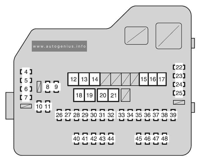
Assignment of the fuses in the Engine Compartment Fuse Box №1
| Fuse | Ampere rating [A} | Circuit | |
| 1 | SPARE | 7,5 | Spare fuse |
| 2 | SPARE | 15 | Spare fuse |
| 3 | SPARE | 25 | Spare fuse |
| 4 | DEF RLY | 10 | Rear window defogger |
| 5 | MIR HTR | 20 | MIR HTR (15 A) |
| 6 | P/OUT | 20 | Power outlet |
| 7 | DOOR 1 | 25 | Multiplex communication system |
| 8 | IGCT NO.3 | 10 | Multiport fuel injection system/sequential multiport fuel injection system |
| 9 | EFI NO.3 | 10 | Multiport fuel injection system/sequential multiport fuel injection system |
| 10 | INJ NO.1 | 15 | Starting system |
| 11 | INJ NO.2 | 10 | Multiport fuel injection system/sequential multiport fuel injection system |
| 12 | HTR | 50 | Air conditioning system |
| 13 | FAN NO.2 | 50 | Electric cooling fan |
| 14 | FAN NO.1 | 50 | Electric cooling fan |
| 15 | RR CLR | 40 | Air conditioning system |
| 16 | RR DEF | 30 | Rear window defogger |
| 17 | PBD | 30 | Power back door |
| 18 | DC/DC | 140 | MIR HTR, P/OUT, DOOR 1, HTR, RR DEF, FAN MAIN, PTC NO.1, RR CLR, PTC NO.2, PTC NO.3, PBD |
| 19 | EPS | 80 | Electric power steering |
| 20 | ABS MTR1 | 50 | Brake system |
| 21 | ABS MTR2 | 50 | Brake system |
| 22 | CRT | 10 | Rear seat entertainment system |
| 23 | RADIO1 | 15 | Audio system |
| 24 | ECU-B | 10 | Steering sensor, gauges and meters, air conditioning system, main body ECU, wireless remote control, smart key system, power back door, on-board diagnosis system |
| 25 | DOME | 10 | Vanity lights, personal lights, interior light, gauges and meters, door courtesy lights, power back door |
| 26 | AMP | 15 | Audio system |
| 27 | TOWING | 30 | Trailer lights |
| 28 | IG2 | 25 | INJ NO.1, INJ NO.2 |
| 29 | STR LOCK | 20 | Steering lock system |
| 30 | IGCT | 30 | IGCT No.2, IGCT No.3, INV-W/P, EFI NO.3 |
| 31 | HAZ | 15 | Turn signal lights |
| 32 | ABS NO.3 | 15 | Electronically controlled brake system |
| 33 | ABS NO.2 | 10 | Electronically controlled brake system |
| 34 | ABS NO.1 | 10 | Capacitor |
| 35 | OIL PMP | 10 | Transaxle fluid cooling system |
| 36 | BATT FAN | 15 | Hybrid system |
| 37 | G/H | 10 | Glass hatch, multiplex communication system |
| 38 | DC/DC-S | 10 | Hybrid system |
| 39 | AM2 | 7,5 | Multiplex communication system |
| 40 | H-LP LH | 15 | Left-hand headlight (high beam) |
| 41 | H-LP RH | 15 | Right-hand headlight (high beam) |
| 42 | H-LP LL | 15 | Left-hand headlight (low beam) |
| 43 | H-LP RL | 15 | Right-hand headlight (low beam) |
| 44 | HORN | 10 | Horn |
| 45 | EFI NO.1 | 10 | Multiport fuel injection system/sequential multiport fuel injection system, smart key system |
| 46 | ETCS | 10 | Multiport fuel injection system/sequential multiport fuel injection system, electronic throttle control system |
| 47 | A/F | 20 | Air fuel ratio sensor |
| 48 | S-HORN | 7,5 | Horn |
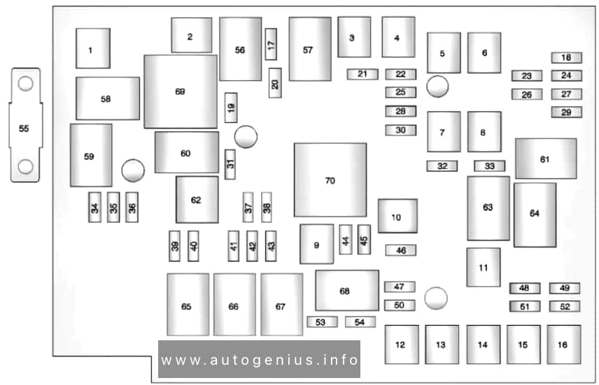
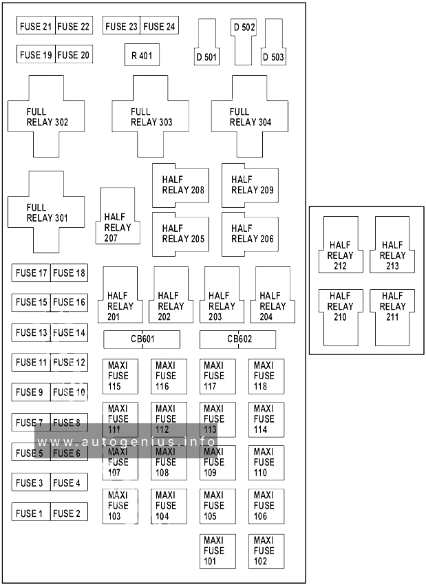
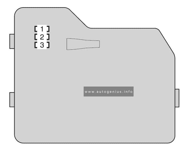
Type B (if equipped)
Assignment of the fuses in the Engine Compartment Fuse Box №2
| Fuse | Ampere rating [A] | Circuit | |
| 1 | INV-W/P | 15 | Hybrid system |
| 2 | IGCT NO.2 | 7,5 | Hybrid system |
| 3 | A/C-D | 10 | Air conditioning system |
Passenger compartment
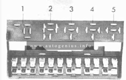
Fuse box location
Push the tab in and lift the lid off.
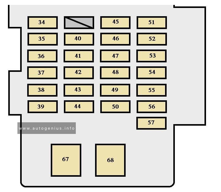
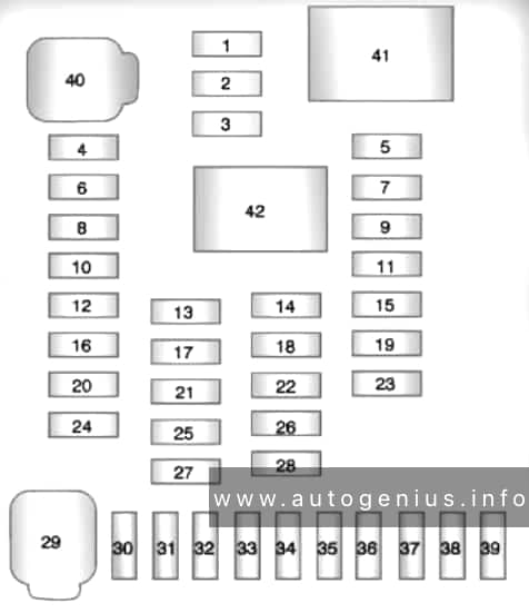
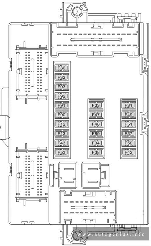
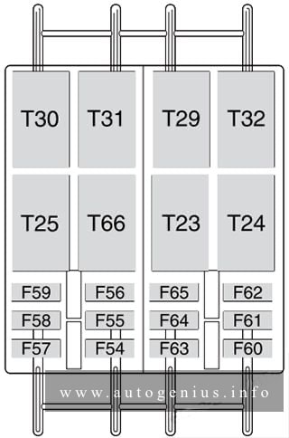
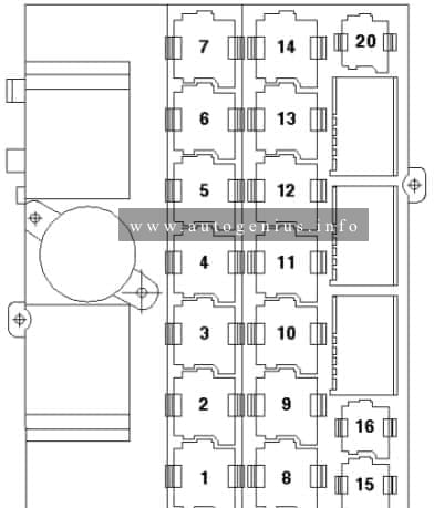
Fuse box diagram
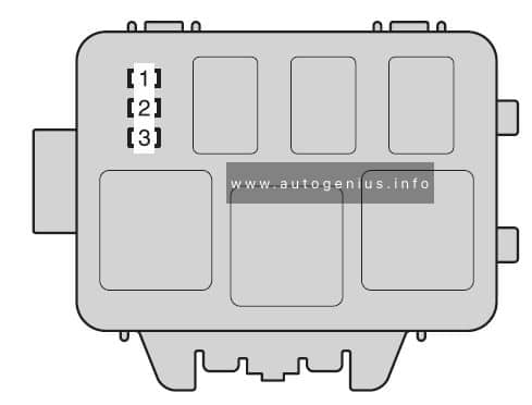
Front side of the fuse block
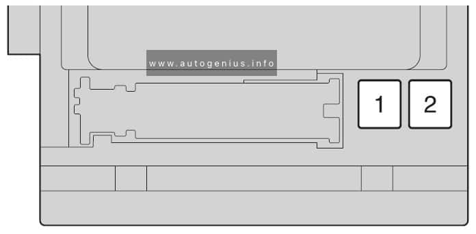
Fuse block
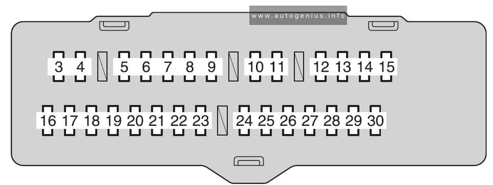
Assignment of the fuses under the instrument panel
| Fuse | Ampere rating [A] | Circuit | |
| 1 | P/SEAT | 30 | Power seat |
| 2 | POWER | 30 | Power windows |
| 3 | RR DOOR RH | 25 | Power windows |
| 4 | RR DOOR LH | 25 | Power windows |
| 5 | FR FOG | 15 | Front fog lights |
| 6 | OBD | 7,5 | On-board diagnosis system |
| 7 | FR DEF | 25 | Windshield wiper de-icer |
| 8 | STOP | 10 | Stop lights |
| 9 | DOOR NO.2 | 25 | Power windows |
| 10 | AM1 | 7,5 | Water pump |
| 11 | RR FOG | 7,5 | No circuit |
| 12 | A/C NO.1 | 10 | Air conditioning system |
| 13 | FUEL OPN | 7,5 | Fuel filler door opener |
| 14 | S/ROOF | 30 | Electric moon roof |
| 15 | TAIL | 15 | Parking lights, tail lights, license plate lights, front fog lights, trailer lights |
| 16 | PANEL | 7,5 | Glove box light, emergency flashers, audio system, outside rear view mirror defoggers, power door lock system, seat heaters, rear seat entertainment system, instrument panel light control dial, electronic controlled transmission switch, transmission, steering switches |
| 17 | ECU IG NO.1 | 10 | Multiplex communication system, electric moon roof, electronically controlled transmission system, power back door, seat heaters, tire pressure warning system, electronic power steering, transmission |
| 18 | ECU IG NO.2 | 7,5 | VDIM |
| 19 | A/C NO.2 | 10 | Air conditioning system, FAN NO.1, FAN NO.2 |
| 20 | WASH | 20 | Windshield wipers and washer |
| 21 | S-HTR | 20 | Seat heaters |
| 22 | GAUGE NO.1 | 10 | Audio system, outside rear view mirror defoggers, back-up lights, charging system, emergency flashers, traction control system, instrument panel light control dial, windshield wiper deicer |
| 23 | FR WIP | 30 | Windshield wipers and washer |
| 24 | RR WIP | 15 | Rear window wiper and washer |
| 25 | IGN | 10 | Multiport fuel injection system/sequential multiport fuel injection system, steering lock system, smart key system, SRS airbag system |
| 26 | GAUGE NO.2 | 7,5 | Gauges and meters, rear view monitor |
| 27 | ECU-ACCESSORY | 7,5 | Power rear view mirror, shift lock system, smart key system |
| 28 | ACCESSORY SOCK NO.1 | 10 | Power outlet |
| 29 | ACCESSORY SOCK NO.2 | 20 | Power outlet |
| 30 | RADIO NO.2 | 7,5 | Audio system, rear seat entertainment system, charging system, interior lights, personal lights |
| 31 | MIR HTR | 15 | Outside rear view mirror defoggers |
WARNING: Terminal and harness assignments for individual connectors will vary depending on vehicle equipment level, model, and market.