Volkswagen Passat (B5; 1996 – 2005) – fuse and relaybox diagram
Year of production: 1996, 1997, 1998, 1999, 2000, 2001, 2002, 2003, 2004, 2005
In this article, we take a look at the Volkswagen Passat (B5, Type 3B), produced between 1996 and 2005. You will find fuse box diagrams for the 1996 –2005 Volkswagen Passat B4, details on the locations of the fuse panels inside the vehicle, and information on the fuse and relay assignments (fuse layout).
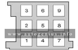
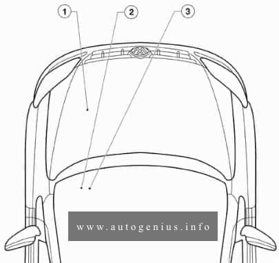
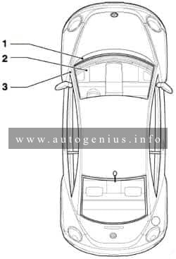
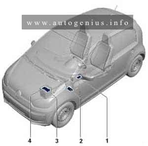
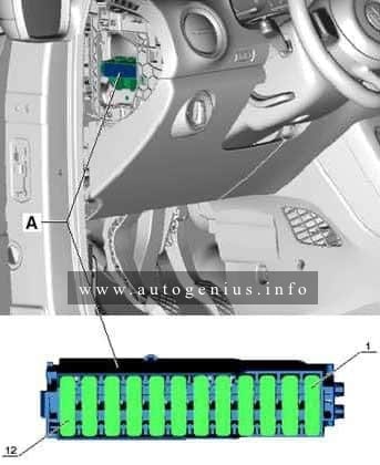
Passenger compartment
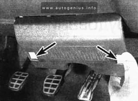
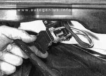
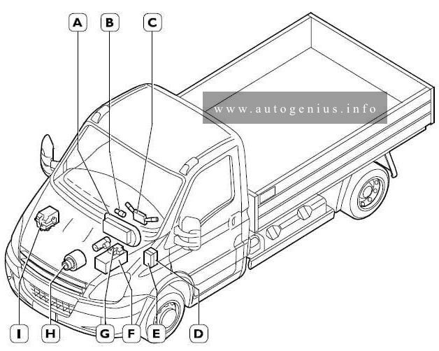
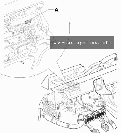
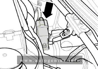
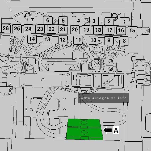
Fuse box location
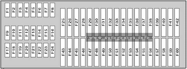
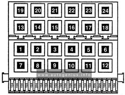
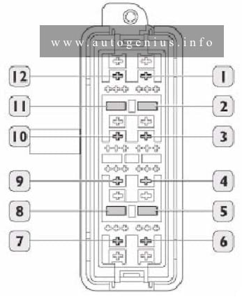
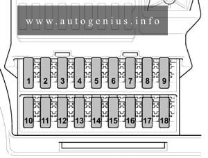
Left cockpit fuse assignment
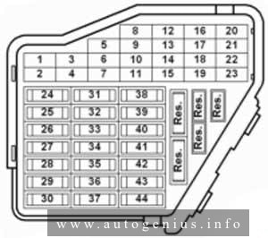
Fuse box diagram
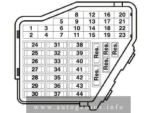
Assignment of the fuses in the passenger compartment (left cocpit)
| № |
A |
Circuits protected |
| 1 | 5 | Heated washer nozzle |
| 2 | 10 | Turn signal system |
| 3 | – | Not used |
| 4 | 5 | License plate light |
| 5 | 10 | Power Seats, air conditioning, telematics, Multi‐Function Steering Wheel, Power sunroof, mirror adjustment, HomeLink |
| 6 | 5 | Comfort module comfort system |
| 7 | 10 | ABS, Cruise Control system, Engine Control Unit |
| 8 | 5 | Automatic headlight beam adjusting |
| 9 | 5 | Parking aid |
| 10 | 5 | CD-Changer Unit, Telematics, Multi‐Function Steering Wheel, Navigation, Radio |
| 11 | 5 | Power Seats with Memory |
| 12 | 10 | B+ (battery positive voltage) for Data Link Connector (DLC) |
| 13 | 10 | Brake lights |
| 14 | 10 | Comfort module system |
| 15 | 10 | Instr. cluster, air conditioning, automatic transmission |
| 16 | 5 | ABS, Steering Angle Sensor |
| 17 | 10 15 |
Power outlet, Telematics |
| 18 | 10 | Right headlight, high beam |
| 19 | 10 | Left headlight, high beam |
| 20 | 15 | Right headlight, low beam |
| 21 | 15 | Left headlight, low beam |
| 22 | 5 | Parklight, right |
| 23 | 5 | Parklight, left |
| 24 | 25 | Wiper system |
| 25 | 30 | Fresh air blower, recirculating control, air conditioning, Power sunroof |
| 26 | 30 | Rear window defogger |
| 27 | 15 | Rear window wiper system |
| 28 | 20 | Fuelpump (FP) |
| 29 | 20 | Engine Control Unit, Coolant Fan |
| 30 | 20 | Sunroof |
| 31 | 15 | Back‐up lights, cruise control system, automatic transmission, Mirror adjustments, diagnostic |
| 32 | 20 | Engine Control Module (ECM), cruise control system |
| 33 | 15 | Cigarette lighter |
| 34 | 15 | Engine Control Module (ECM), injectors |
| 35 | 30 | Trailer socket |
| 36 | 15 | Fog lights |
| 37 | 20 | Radio system, Navigation |
| 38 | 15 | Comfort module system |
| 39 | 15 | Emergency flasher system |
| 40 | 25 | Dual horn |
| 41 | 25 | Telematics |
| 42 | 25 | ABS |
| 43 | 15 | Engine Control Module (ECM) |
| 44 | 30 | Heated seats |
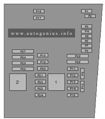
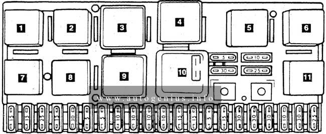
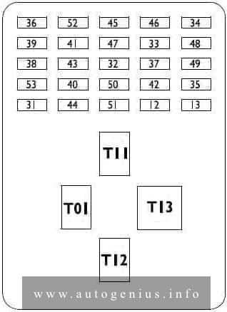
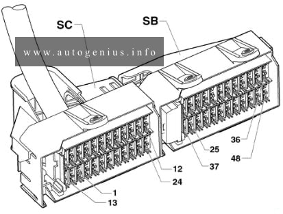
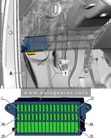
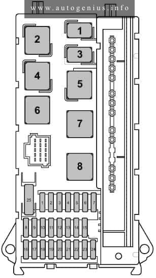
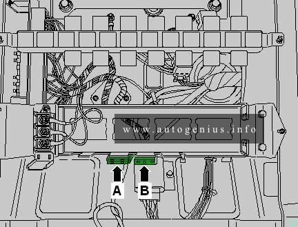
Relay and fuse arrangements
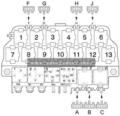
Fuse/Relay box diagram
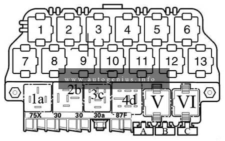
Assignment of the fuses in the fuse/relay box
| Relay arrangement on thirteenfold auxiliary relay panel above relay panel | ||
| 1 | Coolant Fan Control (FC)‐A/C Relay (373) | |
| 2 | Sun-Roof Relay (79) | |
| 3 | A/C Clutch Relay (267) A/C Clutch Relay (384) |
|
| 4 | Daytime Running Lights Change‐Over Relay (173) | |
| 5 | Taxi Alarm Relay High Beam Headlight Relay Emergency Flasher Relay |
|
| 6 | Selector Lever Light Relay | |
| 7 | Fog Light Relay (381) | |
| 8 | Control Module for Multi‐function steering wheel (451) Control Module for Multi‐function steering wheel (452) |
|
| 9 | Control Module for Multi‐function steering wheel (451) Control Module for Multi‐function steering wheel (452) |
|
| 10 | Brake Booster Relay (373) | |
| 11 | Taxi Alarm Relay Emergency Flasher Relay (200) |
|
| 12 | Dual Horn Relay (53) Taxi Alarm Relay |
|
| 13 | Park/Neutral Position (PNP) Relay (175) Starting Interlock Relay‐Clutch Position (53) |
|
| Fuses at thirteenfold relay-panel | ||
| A | 25 | Fuse for Taxi |
| B | 20 | Fuse for Taxi |
| B | 10 | High Beam Headlight left, |
| C | 15 | Fuse for Brake System Vacuum Pump |
| D | 20 | Fuse for Power Outlet (12 V) Rear Console |
| E | 5 | Fuse for Taxi |
| E | 10 | High Beam Headlight right, |
| Relay locations on relay panel | ||
| 1a | Dual Horn Relay (53) | |
| 2b | Load Reduction Relay (370) | |
| 3c | Not used | |
| 4d | Fuel Pump (FP) Relay (372) (409) | |
| V | Wiper/Washer Intermittent Relay (377) (389) Wiper/Washer Intermittent Relay/Rainsensor (192) |
|
| VI | Wiper/Washer Intermittent Relay (377) (389) Wiper/Washer Intermittent Relay/Rainsensor (192) |
|
| Fuses on relay pane | ||
| A | 20 | Fuse for 12v socket I in luggage compartment |
| B | 20 | Fuse for 12v socket II in luggage compartment |
| C | 10 | Fuse for Taxi |
| *Numbers in parentheses indicate production control number stamped on relay housing. | ||
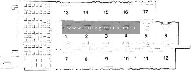
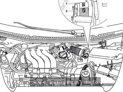
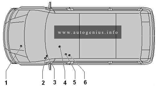
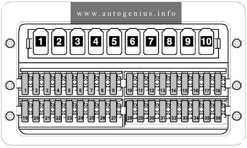
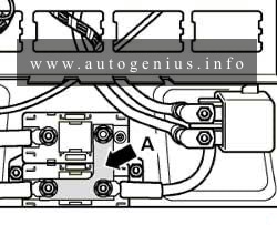
Relay box location
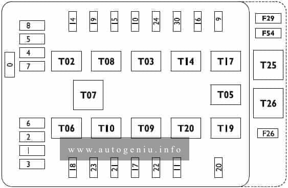
Relay arrangements on eightfold (eight posion) auxiliary relay panel behind relay panel
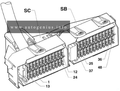
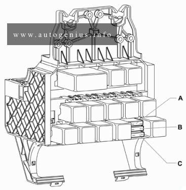
Relay box diagram
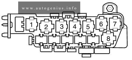
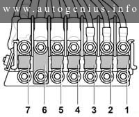
Assignment of the fuses in the relay box
| Relay locations on relay panel | |
| 1 | Not used |
| 2 | Not used |
| 3 | Coolant Fan Control (FC) Relay 80 W (373) |
| 4 | Not used |
| 5 | First Speed Coolant Fan Control (FC) Relay (373) |
| 6 | Coolant Fan Control (FC) Relay (373) |
| 7 | Relay for ABS with ESP (373) |
| 8 | Coolant Fan Control (FC) Relay (370) |
| Fuses at eighthold auxiliary relay panel | |
| 30A | ABS Hydraulic Pump Fuse |
| 30A | Power Window Fuse |
| 30A 40A 60A |
Coolant Fan Fuse |
| 5A | Coolant Fan Fuse |
| 30A 50A |
ABS Hydraulic Pump Fuse |
| 30A | Power Seat Circuit Breaker ‐ Passenger’s Seat |
| 30A | Power Seat Circuit Breaker ‐ Driver’s Seat |
| 30A | Alarm System with Anti‐Theft warning system ‐ Telematics |
| 15A | Alarm System with Anti‐Theft warning system |
| *Numbers in parentheses indicate production control number stamped on relay housing. | |
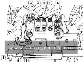
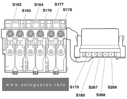
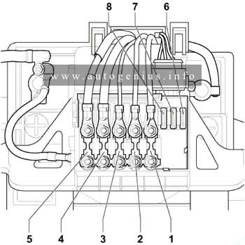
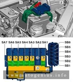
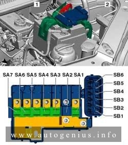
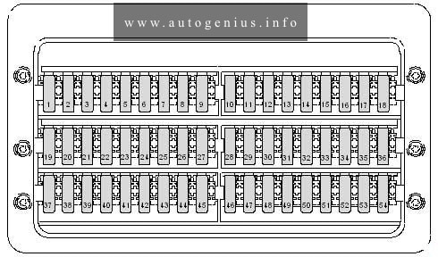
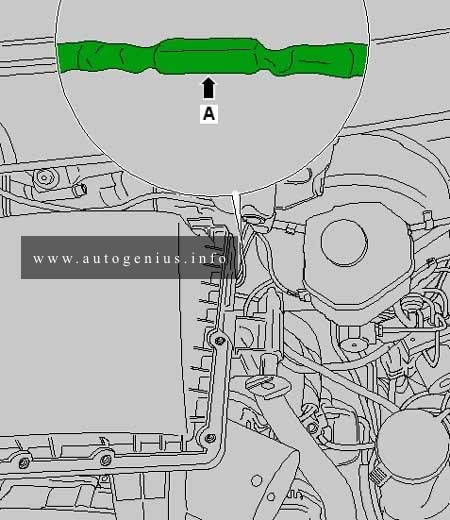
Relay box diagram (Relay and fuse arrangements on Relay Panel)
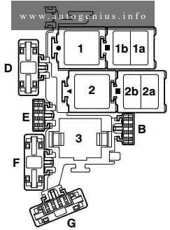
Assignment of the fuses in the relay box
| № | A |
Circuits protected |
| B | 10 | Fuse for Injectors (S116) |
| B | 5 | Fuse for Auxiliary Engine Coolant (EC) Pump |
| D | 50 | Fuse for Secondary Air Pump (S130) |
| E | 40 | Fuse for Ignition coil termial (S115) |
| F | 5 | Engine control Module (ECM) Fuse (S102) |
| G | 10 | Engine Electronics Fuse (S282) |
| 1 | Motronic Engine Control Module Power Supply Relay (167), engine code BDP | |
| 2 | Secondary Air Injection (AIR) Pump Relay (373), (100) | |
| 3 | Motronic Engine Control Module Power Supply Reay (429), (219) Auxiliary Engine Coolant (EC) Pump Relay (53), (411) |
|
WARNING: Terminal and harness assignments for individual connectors will vary depending on vehicle equipment level, model, and market.