Volkswagen Touareg (2010 – 2018) – fuse and relay box diagram
Year of production: 2010, 2011, 2012, 2013, 2014, 2015, 2016, 2017, 2018
This article provides the second-generation Volkswagen Touareg (7P), manufactured between 2010 and 2018. It provides fuse box diagrams for the Volkswagen Touareg models from 2011 to 2018, along with details on the location of the fuse panels within the vehicle. Additionally, you’ll find information on the fuse layout and the functions of each fuse and relay.
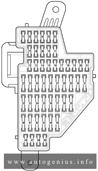
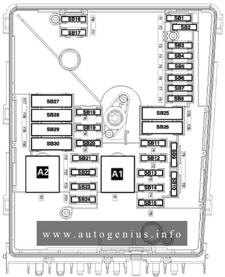
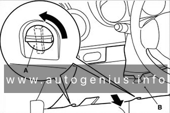
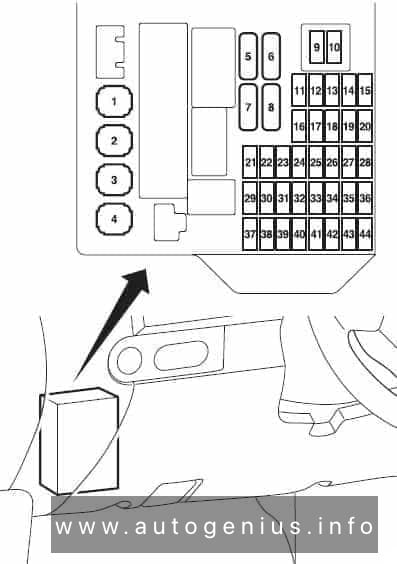
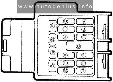
Fuse assignment in fuse box, right-side instrument panel
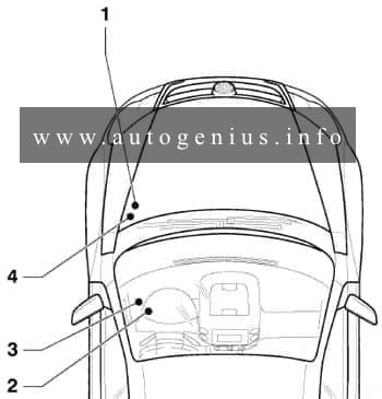
Fuse box diagram and location
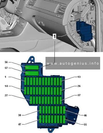
Assignment of the fuses in the right-side of the instrument panel
| No. |
А |
Function/component |
| 1 | – | Not assigned |
| 2 | 15 | Adaptive suspension control unit -J197- |
| 3 | 10 | Axle differential lock control unit -J647- |
| 4 | 30 | Axle differential lock control unit -J647- |
| 5 | 25 156 |
Trailer detector control unit -J345- |
| 6 | 15 | Trailer detector control unit -J345- |
| 7 | 15 256 |
Trailer detector control unit -J345- |
| 8 | 15 256 |
Trailer detector control unit -J345- |
| 9 | 30 | Rear right door control unit -J389- |
| 10 | – | Not assigned |
| 11 | 30 | Front passenger door control unit -J387- |
| 12 | – | Not assigned |
| 13 | 15 | Trailer detector control unit -J345-6 |
| 14 | 10 | Airbag control unit -J234- Front passenger airbag deactivated warning lamp -K145- Seat occupied recognition control unit -J706-3 |
| 15 | 10 | Transfer box control unit -J646- |
| 16 | 5 | Control unit for electromechanical parking brake -J540- Operating unit to regulate suspension height -E281- Left washer jet heater element -Z20- Right washer jet heater element -Z21- Button for TCS and electronic stabilisation program -E256- ABS control unit -J104- Hill descent control button -E618- Electromechanical parking brake button -E538- Auto-hold button -E540-6 Voltage stabiliser -J532-2 |
| 17 | 15 | Front right headlight -MX2- |
| 18 | 30 | Igniter for front passenger side seat belt tensioner 2 -N298- |
| 19 | 5 | Tiptronic switch -F189- Multifunction switch -F125- Automatic gearbox control unit -J217- |
| 20 | 25 | Front passenger seat position control unit -J720-1 Valve block 1 in front passenger seat -N477-1 Control unit for front passenger multicontour seat -J872-1 Control unit for front right seat ventilation -J799-1 Front passenger seat rake adjustment button -E334-1 Front passenger seat longitudinal adjustment switch -E64-1 Front passenger side height adjustment switch -E290-1 Front passenger seat backrest adjustment switch -E98-1 Front passenger seat lumbar support adjustment switch -E177-1 |
| 21 | 25 | Heated rear seats control unit -J786-1 Operating and display unit for rear air conditioning system -E265-1 |
| 22 | – | Not assigned |
| 23 | 25 | Rear lid control unit -J605- |
| 24 | 10 | Climatronic control unit -J255- Operating and display unit for rear air conditioning system -E265-1 |
| 25 | 5 | Control unit for overhead view camera -J928- Reversing camera system control unit -J772- |
| 26 | 30 | Heated rear window relay -J9- |
| 27 | 5 | Remote control receiver for auxiliary coolant heater -R149- |
| 28 | 20 | Gearbox hydraulic pump relay -J510- Transfer box control unit -J646- Automatic gearbox control unit -J217- |
| 28 | 55 206 |
Transfer box control unit -J646- |
| 29 | 30 | ABS control unit -J104- |
| 30 | 5 | Tiptronic switch -F189-5 |
| 31 | 306,7 205 |
Convenience system central control unit -J393- |
| 32 | 30 | Rear fresh air blower -V80-4 |
| 33 | 30 | Convenience system central control unit -J393- |
| 34 | – | Not assigned |
| 35 | 5 | Control unit for vehicle location system -J895-4 |
| 36 | 30 | Convenience system central control unit -J393- |
| 37 | 20 | Automatic gearbox control unit -J217-5 Gearbox hydraulic pump relay -J510-5 |
| 38 | 15 | Cigarette lighter -U1- 12 V socket 2 -U18- Heated rear seats control unit -J786- |
| 39 | 15 | 12 V socket 3 -U19- 12 V socket 4 -U20- |
| 40 | 20 304 |
DC/AC converter with socket, 12 V – 230 V -U13- |
| 41 | 10 | Connection 2 for external audio sources -R231-5 Not assigned6 |
| 42 | 5 | Trailer detector control unit -J345- |
| 43 | 10 | Axle differential lock control unit -J647- |
| 44 | 5 | Air quality sensor -G238- |
| 45 | 30 | Voltage stabiliser -J532-2 |
| 46 | 30 | Voltage stabiliser -J532-2 |
| 47 | 10 | Control unit 1 for information electronics -J794- Display unit for front information display and operating unit control unit -J685- |
| 48 | 30 | Digital sound package control unit -J525-1 |
| 49 | – | Not assigned |
| 50 | 5 | TV tuner -R78-1 Mobile telephone operating electronics control unit -J412-1 |
| 51 | 20 | Radio -R- |
| 52 | 5 | Control unit in dash panel insert -J285- |
| 53 | 5 | DVD changer -R161- |
| 54 | 5 | Interface for external multimedia unit -R215-4 |
| 55 | – | Not assigned |
| 56 | 40 | ABS control unit -J104- |
| 57 | 40 | Control unit for electromechanical parking brake -J540- Transfer box control unit -J646- |
| 1) According to equipment 2) Only models with start/stop system 3) Only for American markets 4) From November 2010 5) From November 2012 6) From August 2014 7) Up to November 2012 |
||
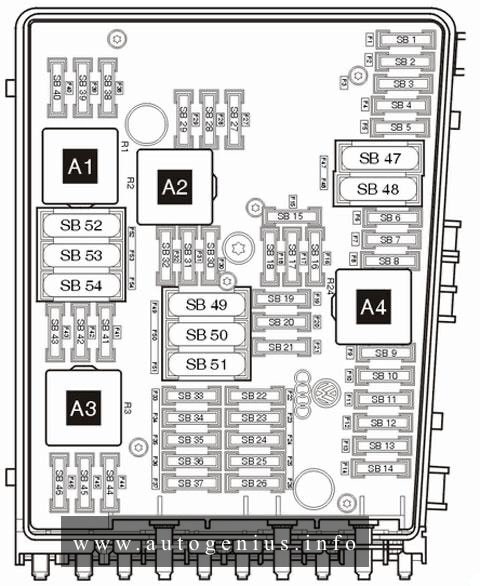
Fuse assignment in fuse box, left-side instrument panel
Fuse box diagram and location
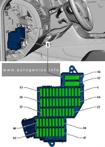
Assignment of the fuses in the left-side of the instrument panel
| No. |
A |
Function/component |
| 1 | 25 | Seat control module |
| 2 | 30 | Auxiliary heater control module |
| 3 | 20 | Horn |
| 4 | 30 | Windscreen wiper motor |
| 5 | 30 | Sunroof control module |
| 6 | 15 | Rear seat backrest release control module |
| 7 | 15 | Steering column adjustment module |
| 8 | 10 | — |
| 9 | 5 | — |
| 10 | 30 | Sunblind control module |
| 11 | 15 | Heated steering wheel |
| 12 | — | — |
| 13 | — | — |
| 14 | 30 | — |
| 15 | 30 | — |
| 16 | 30 | Door function control module, driver |
| 17 | 10 | Alarm system |
| 18 | 30 | — |
| 19 | 10 | — |
| 20 | 30 | — |
| 21 | 10 | Engine coolant pump motor |
| 22 | 30 | — |
| 23 | 7,5 | — |
| 24 | 30 | Heated windscreen |
| 25 | 30 | Heated windscreen |
| 26 | 15 | — |
| 27 | 5 | — |
| 28 | 5 | Hybrid drive system |
| 29 | 5 | Clutch control actuator |
| 30 | 5 | Power steering control module |
| 31 | — | — |
| 32 | 15 | Air conditioning(AC) |
| 33 | 30 | Door function control module, left rear |
| 34 | — | — |
| 35 | — | — |
| 36 | — | Parking brake |
| 37 | 15 | — |
| 38 | 5 | Hybrid drive system |
| 39 | 30 | Clutch control actuator |
| 40 | 30 | — |
| 41 | 10 | — |
| 42 | 5 | Anti-dazzle interior mirror |
| 43 | 7,5 | — |
| 44 | 5 | Heated seats |
| 45 | 5 | Image processing module |
| 46 | 5 | — |
| 47 | 5 | — |
| 48 | 10 | — |
| 49 | 7,5 | — |
| 50 | 30 | Seat belt pretensioners |
| 51 | — | — |
| 52 | 15 | Rear screen wiper motor |
| 53 | 5 | — |
| 54 | 15 | LH headlamp |
| 55 | — | — |
| 56 | 40 | Suspension compressor pump |
| 57 | 40 | AC/Heater blower motor |
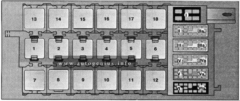
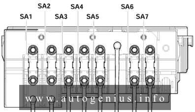
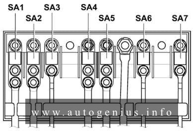
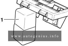
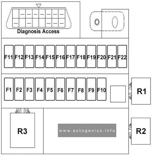
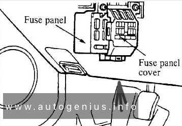
Fuses and relay position assignment in pre-fuse box, under driver seat
Fuse box location
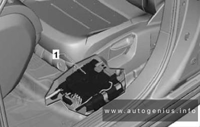
Fuse box diagram
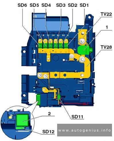

Pre-fuse box, under driver seat
| No. |
A |
Function/component |
| 1 | 100 | Fuse holder B -SB- (SB1 – SB6, SB7 – SB12, SB38 – SB41, SB57) |
| 2 | 50 | Adaptive suspension control unit -J197- |
| 3 | 100 | Fuse holder C -SC- (SC1 – SC4, SC5 – SC8, SC20 – SC23, SC24 – SC26) |
| 4 | 80 | Fuse holder C -SC- (SC9 – SC12, SC27 – SC30, SC37 4 , SC45, SC54, SC56, SC57) |
| 5 | 40 | Fuse holder B -SB- (SB33 – SB36) |
| 6 | 50 | Relay for power sockets -J807- Fuse holder C -SC- (SC38 – SC40) |
| 7 | 60 | Fuse holder C -SC- (SC31 – SC36) Rear fresh air blower -V80-13 |
| 8 | 60 | Wiring connector -TV15- Terminal 30 voltage supply relay -J317- |
| 9 | 125 | Fuse holder B -SB- (SB14 – SB19, SB20 – SB23, SB24, SB25, SB56) |
| 10 | 150 60 |
Auxiliary air heater element -Z35-1 Gearbox hydraulic pump relay -J510-2 |
| 11 | 40 | Terminal 15 voltage supply relay -J329- |
| 12 | 5 | Diagnosis |
| 1) Depending on equipment 2) Only models with start/stop system 3) Only for American markets |
||
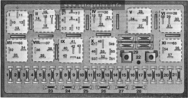
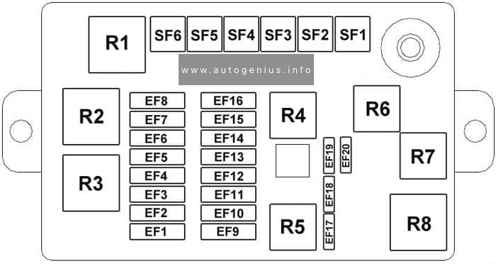
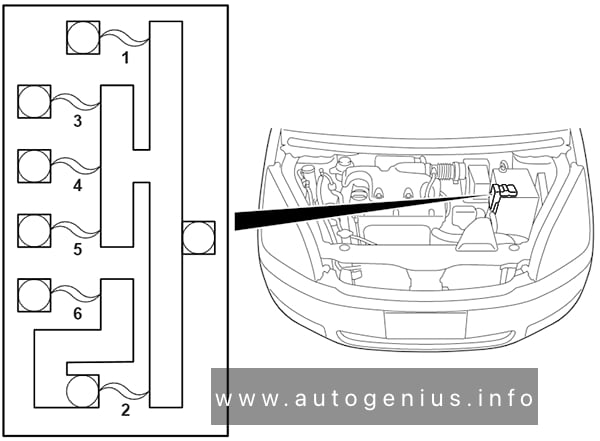
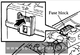
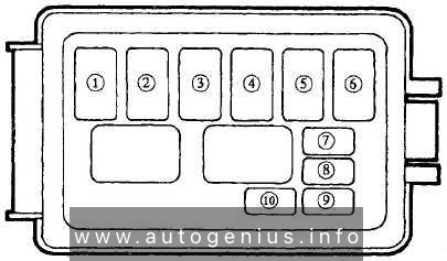
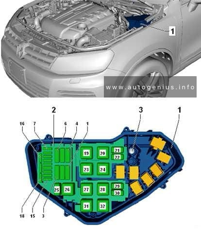
Engine compartment
Fuse box location
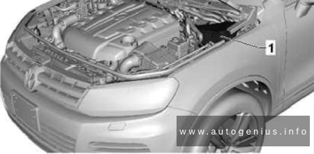
Engine compartment relay & fuse box (3.0l, V6 diesel engine (CASA, CASD, CATA))

| No. |
A |
Function/component |
| 1 | 40 | Starter motor relay -J53- Starter motor relay 2 -J695- Starter relay 1 -J906-1 Starter relay 2 -J907-1 Starter -B- |
| 2 | – | Not assigned |
| 3 | – | Not assigned |
| 4 | – | Not assigned |
| 5 | – | Not assigned |
| 6 | – | Not assigned |
| 7 | 15 | Fuel pressure regulating valve -N276- Fuel metering valve -N290- |
| 8 | 10 | Pump for exhaust gas recirculation cooler -V400- |
| 9 | 30 | Engine control unit -J623- |
| 10 | 10 | Radiator fan control unit -J293- Automatic glow period control unit -J179- Additional coolant pump relay -J496- Brake light switch -F- Exhaust gas recirculation cooler changeover valve -N345- Exhaust gas recirculation cooling bypass valve -N386- Valve for oil pressure control -N428- Throttle valve module -J338- |
| 11 | 5 | Oil level and oil temperature sender -G266- |
| 12 | 10 | Additional coolant pump relay -J496- Residual heat relay -J708- Coolant circulation pump -V50- |
| 13 | 25 | Fuel pump control unit -J538- |
| 14 | 30 | Pump for reducing agent -V437-2 Reversing valve for reducing agent -N473-2 Evaluation unit for reducing agent level -G698-2 |
| 15 | 10 | Terminal 30 voltage supply relay -J317- |
| 16 | 30 | Control unit for reducing-agent heater -J891-2 |
| 17 | 15 | Lambda probe heater -Z19- |
| 18 | 10 | Lambda probe 1 heater after catalytic converter -Z29- |
| 1) Only models with start/stop system 2) Only for American markets |
||
Engine compartment relay & fuse box (3.0l, V6 diesel engine (CJGD, CJMA, CRCA, CNRB))

| No. |
A |
Function/component |
| 1 | 40 | Starter motor relay -J53- Starter motor relay 2 -J695- Starter relay 1 -J906-1 Starter relay 2 -J907-1 Starter -B- |
| 2 | – | Not assigned |
| 3 | – | Not assigned |
| 4 | – | Not assigned |
| 5 | – | Not assigned |
| 6 | – | Not assigned |
| 7 | 15 | Fuel pressure regulating valve -N276- Fuel metering valve -N290- |
| 8 | – | Not assigned |
| 9 | 30 | Engine control unit -J623- |
| 10 | 10 | Radiator fan control unit -J293- Automatic glow period control unit -J179- Additional coolant pump relay -J496- Brake light switch -F- Exhaust gas recirculation cooler changeover valve -N345- Coolant valve for cylinder head -N489- Valve for oil pressure control -N428- Map-controlled engine cooling system thermostat -F265- Right electrohydraulic engine mounting solenoid valve -N145-1 |
| 11 | 5 | Oil level and oil temperature sender -G266- |
| 12 | 10 | Additional coolant pump relay -J496- Residual heat relay -J708- Coolant circulation pump -V50- |
| 13 | 25 | Fuel pump control unit -J538- |
| 14 | 152) | Pump for reducing agent -V437- |
| 15 | 10 | Terminal 30 voltage supply relay -J317- |
| 16 | 30 | Control unit for reducing-agent heater -J891-3) |
| 17 | 15 | Lambda probe heater -Z19- |
| 18 | – | Not assigned |
| 1) Only models with start/stop system 2) Depending on equipment 3) Only for American markets |
||
Engine compartment relay & fuse box (3.0l, V6 diesel engine (CVVA, CVWA))
| No. |
A |
Function/component |
| 1 | 40 | Starter motor relay -J53- Starter motor relay 2 -J695- Starter relay 1 -J906-1 Starter relay 2 -J907-1 Starter -B- |
| 2 | – | Not assigned |
| 3 | – | Not assigned |
| 4 | – | Not assigned |
| 5 | – | Not assigned |
| 6 | – | Not assigned |
| 7 | 15 | Fuel pressure regulating valve -N276- Fuel metering valve -N290- |
| 8 | – | Not assigned |
| 9 | 30 | Engine control unit -J623- |
| 10 | 10 | Radiator fan control unit -J293- Automatic glow period control unit -J179- Additional coolant pump relay -J496- Brake light switch -F- Exhaust gas recirculation cooler changeover valve -N345- Coolant valve for cylinder head -N489- Valve for oil pressure control -N428- Map-controlled engine cooling system thermostat -F265- Right electrohydraulic engine mounting solenoid valve -N145-1 |
| 11 | 5 | Oil level and oil temperature sender -G266- |
| 12 | 10 | Additional coolant pump relay -J496- Residual heat relay -J708- Coolant circulation pump -V50- |
| 13 | 25 | Fuel pump control unit -J538- |
| 14 | 15 | Pump for reducing agent -V437- |
| 15 | 30 | Terminal 30 voltage supply relay -J317- |
| 16 | 30 | Control unit for reducing-agent heater -J891- |
| 17 | 15 | Lambda probe heater -Z19- |
| 18 | – | Not assigned |
Engine compartment relay & fuse box (4.2l, V8 diesel engine (CKDA))

| No. |
A |
Function/component |
| 1 | 40 | Starter motor relay -J53- Starter motor relay 2 -J695- Starter -B- |
| 2 | – | Not assigned |
| 3 | – | Not assigned |
| 4 | – | Not assigned |
| 5 | – | Not assigned |
| 6 | – | Not assigned |
| 7 | 15 | Fuel pressure regulating valve -N276- Fuel metering valve -N290- |
| 8 | 10 | Pump for exhaust gas recirculation cooler -V400- |
| 9 | 30 | Engine control unit -J623- |
| 10 | 10 | Radiator fan control unit -J293- Automatic glow period control unit -J179- Glow period control unit 2 -J703- Additional coolant pump relay -J496- Brake light switch -F- Exhaust gas recirculation cooler changeover valve -N345- Coolant valve for cylinder head -N489- Valve for oil pressure control -N428- Throttle valve module -J338- |
| 11 | 15 | Oil level and oil temperature sender -G266- Heater element for crankcase breather -N79- Heater element 2 for crankcase breather -N483- |
| 12 | 10 | Additional coolant pump relay -J496- Residual heat relay -J708- Coolant circulation pump -V50- |
| 13 | 25 | Fuel pump control unit -J538- |
| 14 | 30 | Engine control unit 2 -J624- |
| 15 | 10 | Terminal 30 voltage supply relay -J317- Engine control unit -J623-Engine control unit 2 -J624- |
| 16 | – | Not assigned |
| 17 | 15 | Lambda probe heater -Z19- Lambda probe heater 2 -Z28- |
| 18 | – | Not assigned |
Engine compartment relay & fuse box (3.0l, V6 petrol engine, hybrid (CGEA, CGFA))

| No. |
A |
Function/component |
| 1 | – | Not assigned |
| 2 | – | Not assigned |
| 3 | 40 | Secondary air pump relay -J299- Secondary air pump motor -V101- |
| 4 | 30 | Vacuum pump relay -J57- Brake servo vacuum pump -V469- |
| 5 | – | Not assigned |
| 6 | – | Not assigned |
| 7 | 20 | Ignition coil 1 with output stage -N70- Ignition coil 2 with output stage -N127- Ignition coil 3 with output stage -N291- Ignition coil 4 with output stage -N292- Ignition coil 5 with output stage -N323- Ignition coil 6 with output stage -N324- |
| 8 | 10 | Low-temperature circuit coolant pump -V468- |
| 9 | 30 | Engine control unit -J623- |
| 10 | 10 | Secondary air pump relay -J299- Radiator fan control unit -J293- Fuel system diagnostic pump -V144- Vacuum pump relay -J57- Brake light switch -F- |
| 11 | 10 | Oil level and oil temperature sender -G266- |
| 12 | 10 | Camshaft control valve 2 -N208- Variable intake manifold changeover valve -N335- Camshaft control valve 1 -N205- |
| 13 | 25 | Fuel pump control unit -J538- |
| 14 | 15 | Secondary air inlet valve -N112- Secondary air inlet valve 2 -N320- Refrigerant shut-off valve 1 for hybrid battery -N516- Valve for oil pressure control -N428- Fuel pressure regulating valve -N276- Activated charcoal filter solenoid valve 1 -N80- |
| 15 | 10 | Terminal 30 voltage supply relay -J317- Engine control unit -J623- |
| 16 | 10 | Coolant pump for high-temperature circuit -V467- |
| 17 | 15 | Lambda probe heater -Z19- Lambda probe heater 2 -Z28- |
| 18 | 10 | Lambda probe 1 heater after catalytic converter -Z29- Lambda probe 2 heater after catalytic converter -Z30- |
Engine compartment relay & fuse box (3.0l, V6 petrol engine (CJTA, CYJA))

| No. |
A |
Function/component |
| 1 | 40 | Starter motor relay -J53- Starter motor relay 2 -J695- Starter -B- |
| 2 | – | Not assigned |
| 3 | 40 | Secondary air pump relay -J299- Secondary air pump motor -V101- |
| 4 | – | Not assigned |
| 5 | – | Not assigned |
| 6 | – | Not assigned |
| 7 | 20 | Ignition coil 1 with output stage -N70- Ignition coil 2 with output stage -N127- Ignition coil 3 with output stage -N291- Ignition coil 4 with output stage -N292- Ignition coil 5 with output stage -N323- Ignition coil 6 with output stage -N324- |
| 8 | 10 | Continued coolant circulation pump -V51- |
| 9 | 30 | Engine control unit -J623- |
| 10 | 10 | Secondary air pump relay -J299- Radiator fan control unit -J293- Additional coolant pump relay -J496- Brake light switch -F- |
| 11 | 7.5 | Oil level and oil temperature sender -G266- |
| 12 | 10 | Camshaft control valve 2 -N208- Variable intake manifold changeover valve -N335- Camshaft control valve 1 -N205- Additional coolant pump relay -J496- Residual heat relay -J708- Coolant circulation pump -V50- |
| 13 | 25 | Fuel pump control unit -J538- |
| 14 | 10 | Secondary air inlet valve -N112- Secondary air inlet valve 2 -N320- Valve for oil pressure control -N428- Activated charcoal filter solenoid valve 1 -N80- |
| 15 | 10 | Main relay -J271- Engine control unit -J623- |
| 16 | 10 | Fuel pressure regulating valve -N276- |
| 17 | 15 | Lambda probe heater -Z19- Lambda probe heater 2 -Z28- |
| 18 | 10 | Lambda probe 1 heater after catalytic converter -Z29- Lambda probe 2 heater after catalytic converter -Z30- |
Engine compartment relay & fuse box (3.6l, V6 petrol engine (CGRA, CMTA))

| No. |
A |
Function/component |
| 1 | 40 | Starter motor relay -J53- Starter motor relay 2 -J695- Starter -B- |
| 2 | – | Not assigned |
| 3 | – | Not assigned |
| 4 | – | Not assigned |
| 5 | – | Not assigned |
| 6 | – | Not assigned |
| 7 | 20 | Ignition coil 1 with output stage -N70- Ignition coil 2 with output stage -N127- Ignition coil 3 with output stage -N291- Ignition coil 4 with output stage -N292- Ignition coil 5 with output stage -N323- Ignition coil 6 with output stage -N324- |
| 8 | 10 | Coolant pump -VX20- |
| 9 | 30 | Engine control unit -J623- |
| 10 | 10 | Air mass meter -G70- Intake air temperature sender -G42- Radiator fan control unit -J293- Brake light switch -F- Fuel system diagnostic pump -V144-1 |
| 11 | 10 | Oil level and oil temperature sender -G266- Heater element for crankcase breather -N79- |
| 12 | 10 | Activated charcoal filter solenoid valve 1 -N80- Intake manifold flap valve -N316- Changeover valve -N180- Coolant regulating valve -N515- |
| 13 | 25 | Fuel pump control unit -J538- |
| 14 | 10 | Fuel pressure regulating valve -N276- Camshaft control valve 1 -N205- Exhaust camshaft control valve 1 -N318- |
| 15 | 10 | Main relay -J271- |
| 16 | – | Not assigned |
| 17 | 15 | Lambda probe heater -Z19- Lambda probe heater 2 -Z28- |
| 18 | 10 | Lambda probe 1 heater after catalytic converter -Z29- Lambda probe 2 heater after catalytic converter -Z30 |
| 1) Only for American markets | ||
Engine compartment relay & fuse box (4.2l, V8 diesel engine (CGNA))

| No. |
A |
Function/component |
| 1 | 40 | Starter relay 1 -J906- |
| 2 | – | Not assigned |
| 3 | 40 | Secondary air pump relay -J299- |
| 4 | – | Not assigned |
| 5 | – | Not assigned |
| 6 | – | Not assigned |
| 7 | 20 | Ignition coil 1 with output stage -N70- Ignition coil 2 with output stage -N127- Ignition coil 3 with output stage -N291- Ignition coil 4 with output stage -N292- Ignition coil 5 with output stage -N323- Ignition coil 6 with output stage -N324- Ignition coil 7 with output stage -N325- Ignition coil 8 with output stage -N326- |
| 8 | 10 | Camshaft control valve 1 -N205- Camshaft control valve 2 -N208- Exhaust camshaft control valve 1 -N318- Exhaust camshaft control valve 2 -N319- |
| 9 | 30 | Engine control unit -J623- |
| 10 | 15 | Radiator fan control unit -J293- Secondary air pump relay -J299- Additional coolant pump relay -J496- Brake light switch -F- Map-controlled engine cooling system thermostat -F265- Activated charcoal filter solenoid valve 1 -N80- Coolant valve for cylinder head -N489- |
| 11 | 5 | Oil level and oil temperature sender -G266- |
| 12 | 10 | Additional coolant pump relay -J496- |
| 13 | 25 | Fuel pump control unit -J538- |
| 14 | 10 | Secondary air inlet valve -N112- Variable intake manifold changeover valve -N156- Intake manifold flap valve -N316- Secondary air inlet valve 2 -N320- Valve for oil pressure control -N428- |
| 15 | 10 | Terminal 30 voltage supply relay -J317- Engine control unit -J623- Engine component current supply relay -J757- |
| 16 | 15 | Fuel metering valve -N290- Fuel metering valve 2 -N402- |
| 17 | 15 | Lambda probe heater -Z19- Lambda probe heater 2 -Z28- |
| 18 | 10 | Lambda probe 1 heater after catalytic converter -Z29- Lambda probe 2 heater after catalytic converter -Z30- |
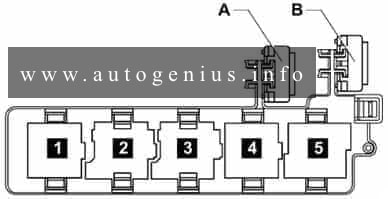
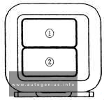
Relay panel 1
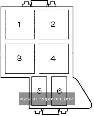
Relay panel 1
| № | Relay |
|---|---|
| 1 | Suspension compressor motor relay |
| 2 | – |
| 3 | – |
| 4 | Horn relay |
| 5 | – |
| 6 | – |
| 7 | Heated rear window relay |
| 8 | – |
| 9 | – |
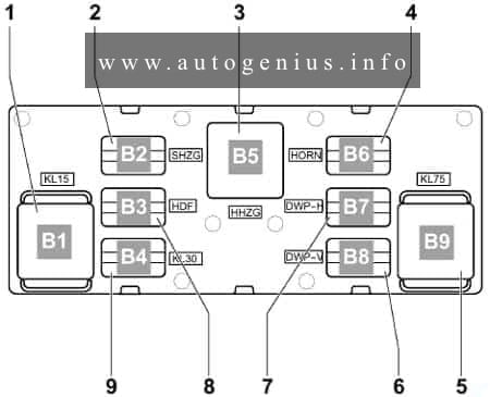
Relay panel 2
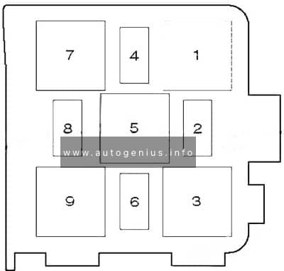
Relay panel 2
| № | Relay |
|---|---|
| 1 | – |
| 2 | – |
| 3 | Auxiliary power socket relay |
| 4 | – |
| 5 | – |
| 6 | Hybrid battery pack cooling fan relay |
WARNING: Terminal and harness assignments for individual connectors will vary depending on vehicle equipment level, model, and market.