VW Jetta (mk4, Type 1J; 1998 – 2005) – fuse and relay box diagram
Year of production: 1998, 1999, 2000, 2001, 2002, 2003, 2004, 2005
The Volkswagen Jetta was a compact family car produced from 1979. In this article, you will find fuse box diagrams for Volkswagen Jetta mk4 models from 1998 to 2005, along with details on the fuse panel locations inside the vehicle and the specific functions of each fuse (fuse layout) and relay.
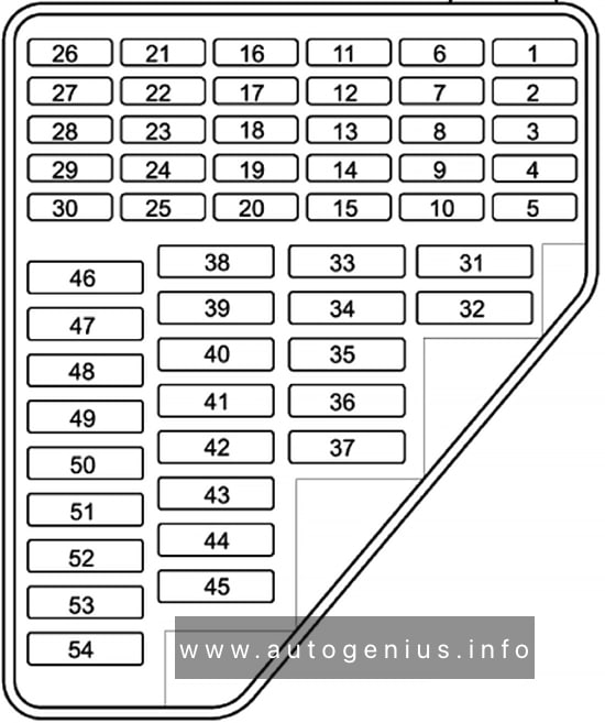
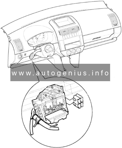
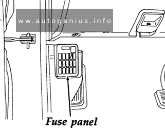
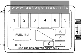
Passenger compartment
Fuse box diagram
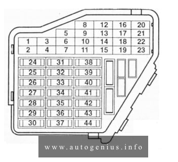
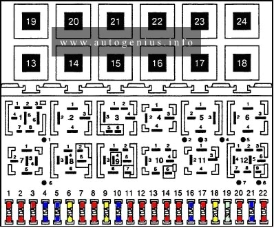
Assignment of the fuses and relays in the passenger comartment
| Fuse | Ampere rating [A] | Description |
| 1 | 10 | Washer nozzle heaters, glove compartment light, memory seat control module |
| 2 | 10 | Turn signal lights |
| 3 | 5 | Fog light relay, instrument panel light dimmer switch |
| 4 | 5 | License plate light |
| 5 | 7,5 | Comfort system, cruise control, Climatronic, A/C, heated seat control modules, automatic day/night interior mirror, control module for multi-function steering wheel, control unit in steering wheel |
| 6 | 5 | Central locking system |
| 7 | 10 | Back-up lights, speedometer vehicle speed sensor (VSS) |
| 8 | — | Open |
| 9 | 5 | Anti-lock brake system (ABS) |
| 10 | 10 | Engine control module (ECM): gasoline engine |
| 5 | Engine control module (ECM): diesel engine, Model Year 2000 | |
| 11 | 5 | Instrument cluster, shift lock solenoid |
| 12 | 7,5 | Data Link Connector (DLC) power supply |
| 13 | 10 | Brake tail lights |
| 14 | 10 | Interior lights, central locking system |
| 15 | 5 | Instrument cluster, transmission control module (TCM) |
| 16 | 10 | A/C clutch, after-run coolant pump |
| 17 | — | Open |
| 18 | 10 | Headlight high beam, right |
| 19 | 10 | Headlight high beam, left |
| 20 | 15 | Headlight low beam, right |
| 21 | 15 | Headlight low beam, left |
| 22 | 5 | Parking lights right, side marker right |
| 23 | 5 | Parking lights left, side marker left |
| 24 | 20 | Windshield and rear window washer pump, windshield wiper motor |
| 25 | 25 | Fresh air blower, Climatronic, A/C |
| 26 | 25 | Rear window defogger |
| 27 | 15 | Motor for rear windshield wiper |
| 28 | 15 | Fuel pump (FP) |
| 29 | 15 | Engine control module (ECM): gasoline engine |
| 10 | Engine control module (ECM): diesel engine | |
| 30 | 20 | Power sunroof control module |
| 31 | 20 | Transmission control module (TCM) |
| 32 | 10 | Injectors: gasoline engine |
| 15 | Injectors: diesel engine | |
| 33 | 20 | Headlight washer system |
| 34 | 10 | Engine control elements |
| 35 | 30 | 12 V power outlet (in luggage compartment) |
| 36 | 15 | Fog lights |
| 37 | 10 | Terminal (86S) on radio, Instrument cluster |
| 38 | 15 | Central locking system (with power windows), luggage compartment light, remote/fuel tank door, motor to unlock rear lid |
| 39 | 15 | Emergency flashers |
| 40 | 20 | Dual tone horn |
| 41 | 15 | Cigarette lighter |
| 42 | 25 | Radio |
| 43 | 10 | Engine control elements |
| 44 | 15 | Heated seats |
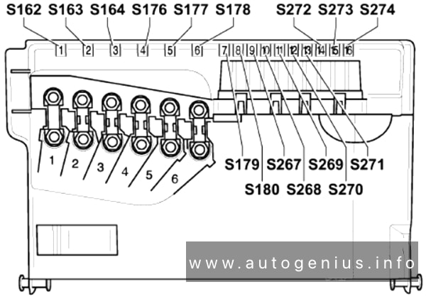
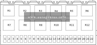
Engine compartment
Fuse box diagram
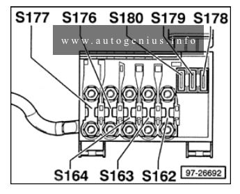
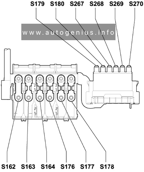
Fuse arangements in fuse bracket/battery
| Fuse | Ampere rating [A] | Description |
| S162 | 50 | Glow plugs (coolant) |
| S163 | 50 | Fuel pump (FP) relay/glow plug relay |
| S164 | 40 | Coolant fan control (FC) control module/coolant fan |
| S177 | 90 / 110 | Generator (GEN) |
| 120 / 150 | ||
| S178 | 30 | ABS (hydraulic pump) |
| S179 | 30 | ABS |
| S180 | 30 | Coolant fan |
WARNING: Terminal and harness assignments for individual connectors will vary depending on vehicle equipment level, model, and market.