The Dodge Ram 3500 (1998–2001) is the heavy-duty version of the Ram truck series, known for its exceptional towing and payload capacity, making it a top choice for those needing a powerful workhorse. As part of the second generation of Dodge Ram trucks, the 3500 was designed to handle the most demanding tasks, from towing heavy trailers to hauling large loads. This truck came with some significant improvements during the late 1990s and early 2000s, especially with the introduction of advanced diesel powertrains and upgrades to the cab and interior configurations.
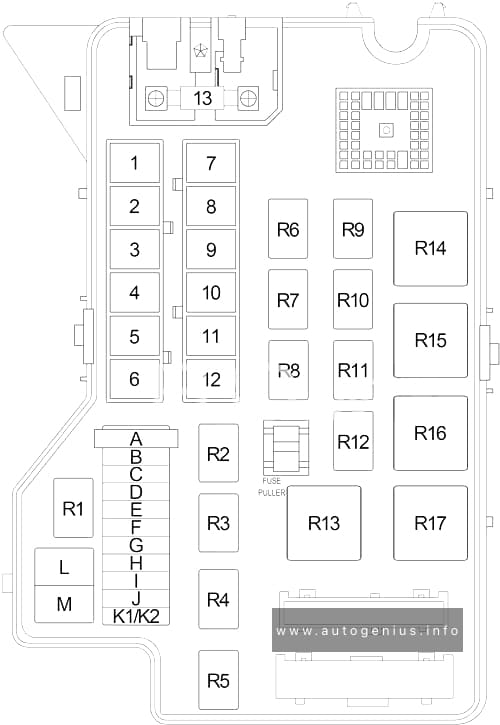
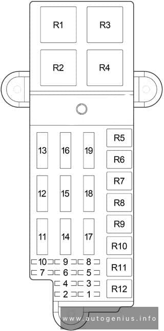
Passenger Compartment Fuse Box
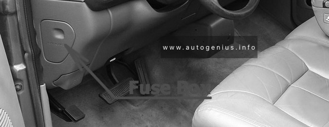
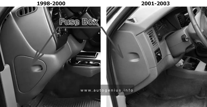
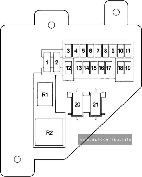
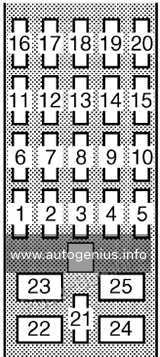
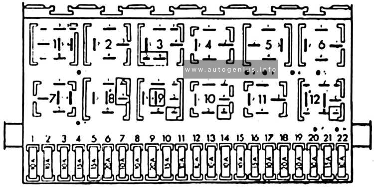
Fuse box location
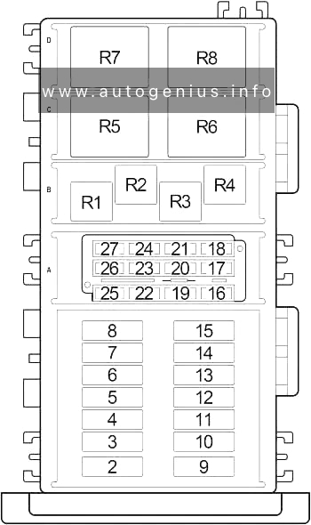
The fuse panel is located behind the cover on the driver’s side of the instrument panel.
Powertrain Control Module, Fuel Pump Relay (Gasoline), Engine Control Module (Diesel)
10
10
Combination Flasher
11
10
Automatic Day/Night Mirror, Overhead Console, Central Timer Module, EVAP/Purge Solenoid, Fuel Heater Relay (Diesel), Air Conditioner Compressor Clutch
12
10
Power Mirror Switch, Dome Lamp, Cargo Lamp, Data Link Connector, Radio, Glove Box Lamp and Switch, Overhead Console, Underhood Lamp, Left Visor/Vanity Lamp, Right Visor/Vanity Lamp
13
10
Driver Door Window/Lock Switch, Passenger Door Window/Lock Switch, Central Timer Module
14
10
Cluster
15
20
Cigar Lighter
16
–
–
17
10
Cluster
18
10
Airbag Control Module
19
10
Airbag Control Module, Passenger Airbag On/Off Switch
20
20
Circuit Breaker: Driver Door Window/Lock Switch, Passenger Door Window/Lock Switch
21
20
Circuit Breaker: Driver Power Seat Switch, Passenger Power Seat Switch
The Dodge Ram 2500 (1998–2001) was part of the second generation of Dodge Ram trucks, which debuted in 1994 and was produced until 2002. The Ram 2500 was the heavy-duty version of the Dodge Ram lineup, offering more towing capacity, payload capability, and durability compared to the half-ton Ram 1500. This truck was particularly popular with those needing a vehicle for heavy work such as towing trailers, hauling heavy loads, or off-roading.
Passenger Compartment Fuse Box
Fuse box location
The fuse panel is located behind the cover on the driver’s side of the instrument panel.
Powertrain Control Module, Fuel Pump Relay (Gasoline), Engine Control Module (Diesel)
10
10
Combination Flasher
11
10
Automatic Day/Night Mirror, Overhead Console, Central Timer Module, EVAP/Purge Solenoid, Fuel Heater Relay (Diesel), Air Conditioner Compressor Clutch
12
10
Power Mirror Switch, Dome Lamp, Cargo Lamp, Data Link Connector, Radio, Glove Box Lamp and Switch, Overhead Console, Underhood Lamp, Left Visor/Vanity Lamp, Right Visor/Vanity Lamp
13
10
Driver Door Window/Lock Switch, Passenger Door Window/Lock Switch, Central Timer Module
14
10
Cluster
15
20
Cigar Lighter
16
–
–
17
10
Cluster
18
10
Airbag Control Module
19
10
Airbag Control Module, Passenger Airbag On/Off Switch
20
20
Circuit Breaker: Driver Door Window/Lock Switch, Passenger Door Window/Lock Switch
21
20
Circuit Breaker: Driver Power Seat Switch, Passenger Power Seat Switch
The Dodge Ram 1500 (1998–2001) was part of the second generation of Dodge Ram trucks, which initially debuted in 1994. During this period, Dodge made incremental updates to the truck’s design, technology, and performance to keep it competitive in the full-size pickup market. This generation is known for its bold design, capable powertrains, and improved comfort and features compared to earlier models.
Passenger Compartment Fuse Box
Fuse box location
The fuse panel is located behind the cover on the driver’s side of the instrument panel.
Powertrain Control Module, Fuel Pump Relay (Gasoline), Engine Control Module (Diesel)
10
10
Combination Flasher
11
10
Automatic Day/Night Mirror, Overhead Console, Central Timer Module, EVAP/Purge Solenoid, Fuel Heater Relay (Diesel), Air Conditioner Compressor Clutch
12
10
Power Mirror Switch, Dome Lamp, Cargo Lamp, Data Link Connector, Radio, Glove Box Lamp and Switch, Overhead Console, Underhood Lamp, Left Visor/Vanity Lamp, Right Visor/Vanity Lamp
13
10
Driver Door Window/Lock Switch, Passenger Door Window/Lock Switch, Central Timer Module
14
10
Cluster
15
20
Cigar Lighter
16
–
–
17
10
Cluster
18
10
Airbag Control Module
19
10
Airbag Control Module, Passenger Airbag On/Off Switch
20
20
Circuit Breaker: Driver Door Window/Lock Switch, Passenger Door Window/Lock Switch
21
20
Circuit Breaker: Driver Power Seat Switch, Passenger Power Seat Switch
Year of production: 2000, 2001, 2002, 2003, 2004,2005, 2006
Volkswagen Lupo was produced mainly in the body of a 3-door hatchback in 1998, 1999, 2000, 2001, 2002, 2003, 2004, 2005 and 2006. Positioned as a city car with low fuel consumption. In this material you will find a designation of the purpose of fuses and relays in Volkswagen Lupo, diagrams of the boxes in which they are located.
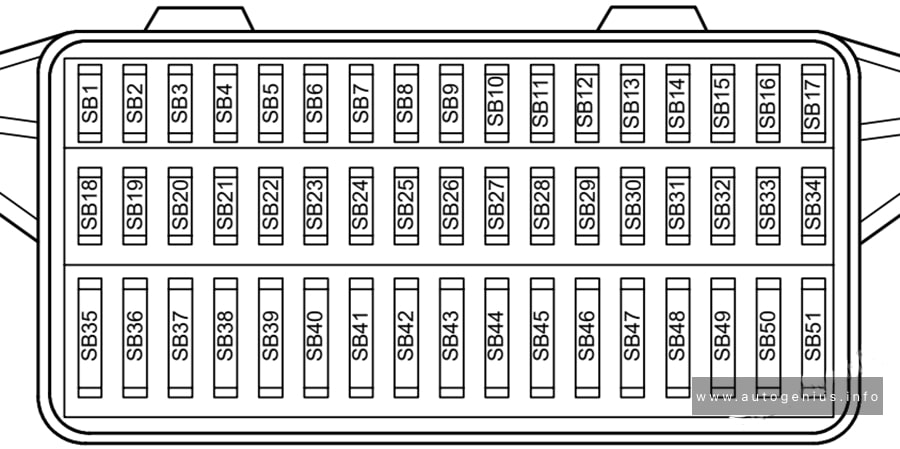
Passenger compartment
Fuse box location
The fuse panel is located behind the cover on the driver’s side of dash panel.
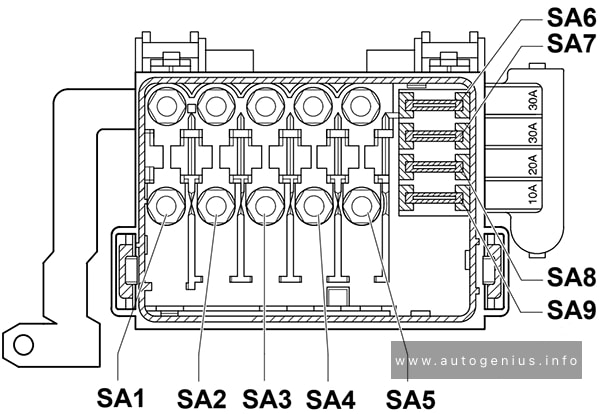
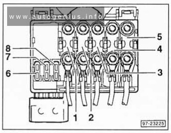
Fuse carrier B Fuse SA2 is located in luggage compartment next to battery
SA3
50A
Engine glow plugs
SA4
80A
Electro-hydraulic power steering motor (ARR, AYZ)
Coolant heater elements (ARR, AYZ)
Radiator fan control unit (only models with air conditioner, ARR, AYZ)
Radiator fan (ARR, AYZ)
SA5
30A
Radiator fan (AMF)
SA6
30A
ABS with EDL control unit
SA7
30A
ABS with EDL control unit
SA8
10A/20A
Radiator fan (AVY, ARR)
Radiator fan control unit (only models with air conditioner, AVY, ARR)
SA9
30A/10A
Radiator fan control unit (only models with air conditioner, AVY, ARR)
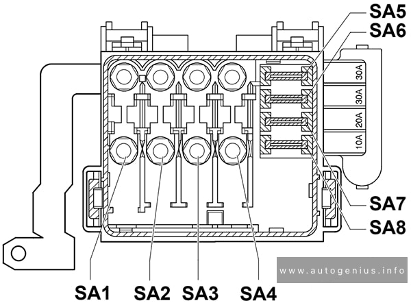
WARNING: Terminal and harness assignments for individual connectors will vary depending on vehicle equipment level, model, and market.
Toyota Land Cruiser (70, AU 78/79; 2000 – 2006) – fuse and relay box diagram
Year of production: 2000, 2001, 2002, 2003, 2004, 2005, 2006
This article provides fuse box diagrams for the Toyota Land Cruiser 78/79 (Australia) models from 2000 to 2006. It also includes details on the location of the fuse panels within the vehicle and explains the function and layout of each fuse.
Passenger Compartment Fuse Boxes
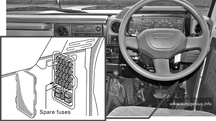
Fuse Box Location
Remove the lid to access.
Toyota Land Cruiser (2000 – 2006) – fuse and relay box – location passenger compartment
Fuse Box Diagrams
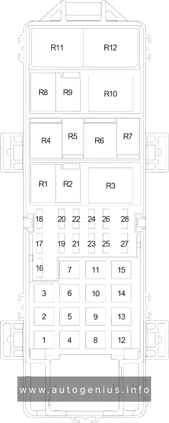
Toyota Land Cruiser (2000 – 2006) – fuse and relay box diagram – passenger compartment
Assignment of the fuses under the instrument panel
№
Name
Amp
Description
1
SPARE
7.5A
Spare fuse
2
SPARE
15A
Spare fuse
3
CHARGE
7.5A
Gasoline: No circuit
IGN
7.5A
1HD-FTE engine: Electronically controlled fuel injection pump system
4
CIG
15A
Cigarette lighter, clock, radio
5
EFI
15A
Gasoline: Multiport fuel injection system / sequential multiport fuel injection system
ECD
15A
1HD-FTE engine: Electronically controlled fuel injection pump system
6
A.C
10A
Air conditioning system
7
TURN
10A
Turn signals lights
8
DEFOG
15A
No circuit
9
WIPER
20A
Windshield wipers and washer, rear window wiper and washer, back-up lights
10
ENGINE
15A
Charging system, emission control system, gauges and meters, service reminder indicators and warning buzzer
11
ST
30A
Diesel: Starting system
12
STOP
10A
Stop lights
13
DOME
10A
Interior light, luggage compartment light, clock, radio
14
RADIO
10A
Diesel: No circuit
15
ECU-B
10A
Diesel; 2003-2006: Exhaust gas recirculation system
In this article, we focus on the post-facelift second-generation Jeep Cherokee (XJ), manufactured between 1997 and 2001. You’ll find fuse box diagrams for the 1997, 1998, 1999, 2000, and 2001 models, along with details on the locations of the fuse panels inside the vehicle and information on the function and layout of each fuse and relay.
Passenger compartment fuse box
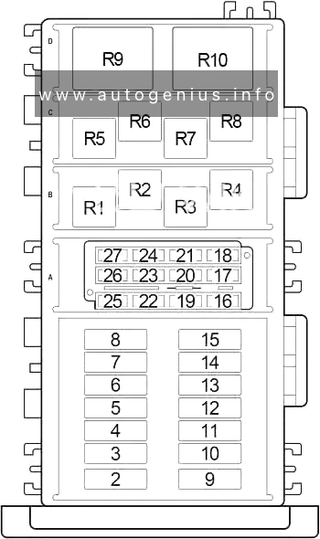
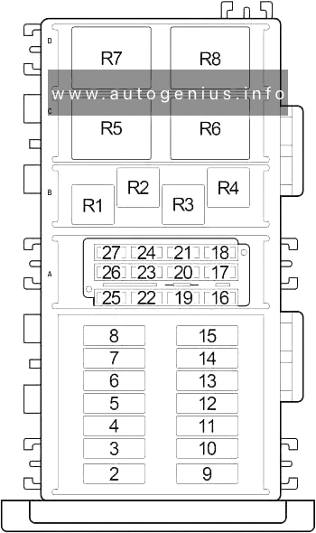
Fuse Box Location
It is located behind the lid under the glove compartment.
Instrument Cluster, Radio, Rear Wiper/Washer Switch, A/C Heater Control or Heater Control, Rear Window Defogger Switch, Extended Idle Switch, Front Fog Lamp Switch, Rear Fog Lamp Switch, Transmission Range Indicator Illumination (PRNDL), Transfer Case Switch Illumination
7
10
Left Tail Lamp, Left Front Park Lamp, Left Side Marker Lamp, Trailer Tow Connector, License Lamp, Front Fog Lamp Relay No.1 (’98-’01), Front Fog Lamp Switch, Fog Lamp Relay
Jeep Grand Cherokee (WJ; 1999 – 2005) – fuse and relay box diagram
Year of production: 1999, 2000, 2001, 2002, 2003, 2004, 2005
In this article, we consider the second-generation Jeep Grand Cherokee (WJ), produced from 1999 to 2005. Here you will find fuse box diagrams of Jeep Grand Cherokee 1999, 2000, 2001, 2002, 2003, 2004 and 2005, get information about the location of the fuse panels inside the car, and learn about the assignment of each fuse (fuse layout) and relay.
Passenger compartment fuse box
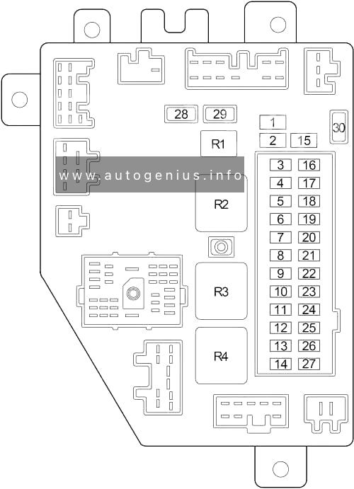
Fuse box location
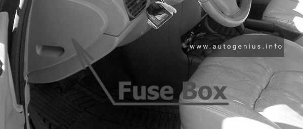
It is located under the instrument panel on the driver’s side, behind a plastic cover near the OBD2 port.
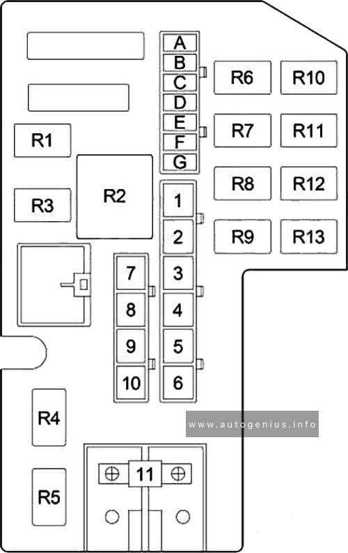
Fuse box diagram
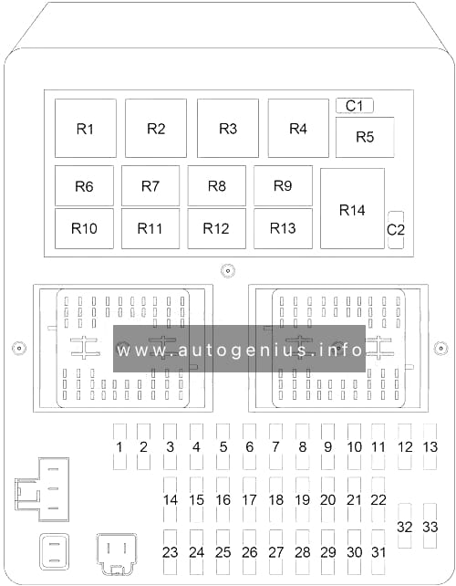
Jeep Grand Cherokee (WJ; 1999 – 2005) – fuse an relay box diagram -passenger compartment
Assignment of the fuses and relay in the instrument panel
No.
A
Description
1
–
–
2
–
–
3
10
Left Headlamp (High Beam)
4
15
Combination Flasher
5
25
Radio, Amplifier
6
15
Park Lamp Relay (Park Lamp, Tail Lamp, License Lamp, Trailer Tow Connector, Headlamp Leveling Switch)
7
10
Body Control Module, Underhood Lamp, Sentry Key Immobilizer Module, Automatic Zone Control Module, Automatic Headlamp Light Sensor/VTSS LED, Remote Keyless Module
8
15
Rear Wiper Motor, Courtesy Lamp, Glove Box Lamp, Cargo Lamp, Overhead Map Lamp, Door Handle Lamp, Vehicle Information Center, Liftgate Flip-Up Push Button Switch, Security System Module, Visor/Vanity Lamp
9
20
Front Power Outlet, Rear Power Outlet, Power Connector
10
20
Adjustable Pedals (?-’04)
11
10
Automatic Zone Control Module (AZC), Manual Temperature Control (MTC)
12
10
Fuel Pump Relay, Automatic Shut Down Relay, Powertrain Control Module, Transmission Control Relay (4.7L)
13
–
–
14
10
Left Headlamp (Low Beam)
15
10
Right Headlamp (Low Beam)
16
10
Right Headlamp (High Beam)
17
10
Data Link Connector, Instrument Cluster
18
20
Trailer Tow Brake Lamp Relay, Electric Brake (’99-’01-?)
30
Trailer Tow Brake Lamp Relay, Electric Brake (?-’04)
19
10
ABS
20
10
Combination Flasher, Automatic Zone Control Module (AZC), Manual Temperature Control (MTC), Temperature Valve Actuator (MTC), Transmission Solenoid/TRS Assembly (4.7L), Park/Neutral Position Switch (4.0L, 3.1L TD), Driver/Passenger Heated Seat Switch
Body Control Module, Instrumeent Cluster, Sentry Key Immobilizer Module, Vehicle Information Center, Automatic Day/Night Mirror, Security System Module
23
15
Stop Lamp Switch
24
15
Front Fog Lamp Relay, Body Control Module
25
20
Sunroof Delay Relay, Body Control Module
26
15
Cigar Lighter
27
15
Rear Fog Lamp Relay
28
10
Body Control Module
29
10
Cigar Lighter Relay, Right Multi-Function Switch
30
15
Radio
31
10
Starter Relay, Transmission Control Module (4.7L)
32
10
Airbag Control Module
33
10
Airbag Control Module
Circuit Breaker
C1
20
Front Wiper Motor, Wiper (On/Off) Relay (Wiper (High/Low) Relay)
C2
20
Power Seat
Relay
R1
Low Beam / Daytime Running Lamp
R2
Cigar Lighter
R3
Combination Flasher
R4
Rear Window Defogger
R5
Rear Fog Lamp
R6
Low Beam
R7
High Beam
R8
Sunroof Delay
R9
–
R10
Front Fog Lamp
R11
–
R12
Park Lamp
R13
–
R14
–
Engine compartment fuse box
Fuse box location
The Power Distribution Center is located near the battery (left or right depending on the version).
Fuse box diagram
Jeep Grand Cherokee (WJ; 1999 – 2005) – fuse an relay box diagram -engine compartment
Assignment of the fuses and relay in power distribution center
Chrysler Cirrus (1995 – 2000) – fuse and relay box diagram
Year of production: 1995, 1996, 1997, 1998, 1999, 2000
The Chrysler Cirrus is a mid-size sedan that was produced by Chrysler from 1995 to 2000. Part of Chrysler’s “Cloud Car” series, the Cirrus shared its platform with the Dodge Stratus and Plymouth Breeze, with each model offering slightly different features and trim levels. The Cirrus was designed to offer a balance of style, performance, and comfort in the competitive mid-size sedan market of the 1990s.
The Chrysler Cirrus was a stylish, comfortable, and reasonably well-equipped sedan for its time. It offered a good blend of power (particularly with the V6 engine), a smooth ride, and modern design cues. While it is no longer in production, the Cirrus remains a memorable part of Chrysler’s history in the mid-size sedan segment.
Passenger Compartment Fuse Box
Fuse Box Location
Chrysler Cirrus (1995 – 2000) – fuse and relay location – passenger compartment
Fuse Box Diagram
Chrysler Cirrus (1995 – 2000) – fuse and relay diagram – passenger compartment
Assignment of fuses in the instrument panel
No.
A
Protected Component
1
30
Blower Motor
2
20
Convertible: Right Headlamp (High Beam), Daytime Running Lamp Module
10
Right Headlamp (High Beam), Daytime Running Lamp Module
3
20
Convertible: Left Headlamp (High Beam)
10
Left Headlamp (High Beam)
4
15
Back-Up Lamp (Back-Up Lamp Switch (M/T), Transmission Range Sensor (A/T)), Power Top Relay (Convertible), Daytime Running Lamp Module, Power Door Lock Switch, Power Mirror Switch, Automatic Day/Night Mirror, Steering Proportional Steering Module
5
10
Dome Lamp, Data Link Connector, Power Antenna, Overhead Map Lamp, Trunk Lamp, Traveler, Body Control Module, Radio, Glove Box Lamp, Visor/Vanity Lamp, Universal Garage Door Opener, Automatic Day/Night Mirror, Illuminated Entry Relay, Courtesy Lamp, Power Door Lock Switch, Door Arm/Disarm Switch, Key-In Halo Lanp, Sunroof Control Module
6
10
Heated Mirror, A/C Heater Control
7
20
’98-’00: Instrument Cluster, Headlamp Switch
15
’95-’97: Headlamp Switch
8
20
Cigar Lighter/Power Outlet, Horn Relay
9
15
Body Control Module
10
20
Rear Fog Lamp Switch, Daytime Running Lamp Module
11
10
Body Control Module, Instrument Cluster, Autostick Switch, Transmission Control Module
12
10
Left Headlamp (Low Beam), Daytime Running Lamp Module
13
20
Right Headlamp (Low Beam), Front Fog Lamp Switch
14
10
Radio
15
10
Combination Flasher, Seat Belt Control Module (Convertible), Intermittent Wiper Relay, Wiper (High/Low) Relay, Rear Window Defogger Relay
16
10
Airbag Control Module
17
10
Airbag Control Module
Circuit Breaker
18
20
Power Seat Switch, Decklid Release Relay
19
20
Power Window, Master Power Window Switch, Window Timer Module, Sunroof Control module
Relay
R1
Headlamp Delay
R2
Horn
R3
Rear Window Defogger
Engine Compartment Fuse Box
Fuse Box Location
Chrysler Cirrus (1995 – 2000) – fuse and relay location – engine compartment
Fuse Box Diagram
Chrysler Cirrus (1995 – 2000) – fuse and relay diagram – engine compartment
Assignment of fuses in the engine compartment
No.
A
Protected Component
1
10
Oxygen Sensor Downstream
2
20
ABS
3
20
Transmission Control Module, Transmission Control Relay
Year of production: 1990, 1991, 1992, 1993, 1994, 1995, 1996, 1997, 1998, 1999, 2000, 2001, 2002, 2003
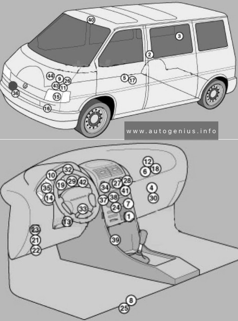
Volkswagen Transporter T4 – represents the 4th generation of the legendary Transporter series. This model was produced in 1990, 1991, 1992, 1993, 1994, 1995, 1996, 1997, 1998, 1999, 2000, 2001, 2002 and 2003 with diesel and gasoline engines with different wheelbases: short and long, and with different roof height. Also on the T4, Volkswagen continued its lineup of luxury Caravelle, California and Multivan models. In this article, we will show the location of all electronic control sides and a detailed designation of the purpose of fuses and relays Volkswagen T4 with box diagrams in which they are located.
Air conditioning control unit 1 – with automatic temperature control – in the heater control panel, front
2
Air conditioning control unit 2 – with automatic temperature control – in the heater control panel, rear – central pillar
3
Evaporator Fan Control Unit (A / C) – With Rear A / C – Behind Right Rear Trim Panel
4
Air conditioning / heater fan motor control unit 1 – with automatic temperature control – front – fan unit
5
Air conditioning / heater blower motor control unit 2- with automatic temperature control – rear- bottom of the body, in the center
6
Aerial amplifier – behind the dash, passenger side
7
Alternator resistor – near additional relays – CV / AUF, with alternator 150A / automatic transmission / automatic temperature control – behind the central part of the dashboard
8
Additional battery – under the driver’s seat
9
Accumulator battery
10
Central locking signal control unit – behind the dashboard
11
Cruise control unit (with throttle motor) – cruise control is controlled by the ECM
12
Electronic cruise control module (without throttle motor) – behind dash, passenger side
13
Diagnostic connector (DLC) – instrument panel, driver’s side
14
Diagnostic unit – 05/99 (except for AAC / ABL / AET / AES / AJA) – in the instrument cluster
15
Cooling Fan Motor Relay – Behind Left Headlight
16
Cooling Fan Motor 1/2 Resistor – Behind Left Headlight
17
Coolant heater control unit (with additional coolant heater – D3W / B4W / D4W) – in the heater – underbody, in the center
18
Coolant heater control unit (with optional coolant heater – B7W / D7W) – behind the dash, passenger side
19
Engine oil pressure warning buzzer – in instrument cluster control unit
Windshield wiper / washer, heaters for windshield washer nozzles (05/01)
6
30
Air conditioning system, heater fan motor
7
10
Front right side / rear right side lamps
8
10
Lamps front left / rear left
9
20
Heated rear window, heated outside mirror
10
15
Fog lights
11
10
Left headlamp-high beam
12
10
RH headlamp-high beam
13
10
Sound signal
14
10
ABS system (with ESP), automatic transmission control system, additional equipment, central locking, cruise control system, power windows, power rear-view mirrors on the doors, reverse light (s)
Heater blower motor relay – automatic temperature control
5
(152)
Heater radiator coolant valve relay (rear heater)
6
(38)
Air intake changeover actuator relay (A / C / heater)
7
(53)
Alternator relay (AES, with 150A alternator)
8
(53)
Alternator relay (ACV / AUF, with alternator 150A / automatic / automatic temperature control)
9
(175)
Start inhibit switch relay / reversing lamp relay
10
(87)
Wheel hub connection control unit
Another unit can be located under the driver’s seat. The following items may be located there: (214/426) Relay for additional battery, (403) Relay for additional heater, (30A) Additional liquid heating system, (5A) Sockets , etc.
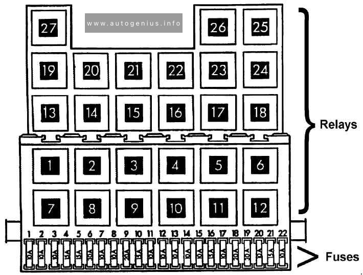
Engine compartment
Fuse box location
This unit is located on the cover in front of the battery.