Dodge RAM 2500 (1998 – 2001) – fuse and relay box diagram
Year of production: 1998, 1999, 2000, 2001
The Dodge Ram 2500 (1998–2001) was part of the second generation of Dodge Ram trucks, which debuted in 1994 and was produced until 2002. The Ram 2500 was the heavy-duty version of the Dodge Ram lineup, offering more towing capacity, payload capability, and durability compared to the half-ton Ram 1500. This truck was particularly popular with those needing a vehicle for heavy work such as towing trailers, hauling heavy loads, or off-roading.
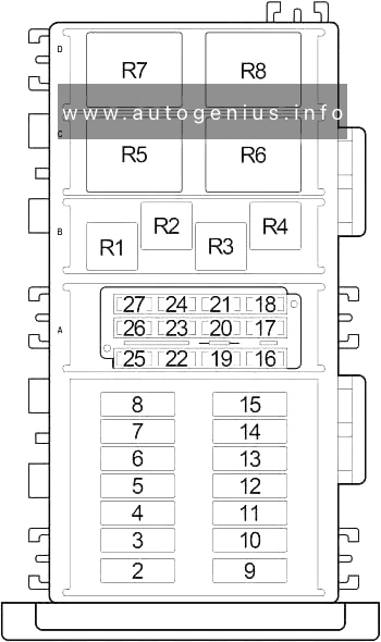
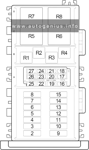
Passenger Compartment Fuse Box
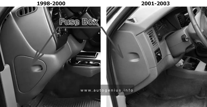
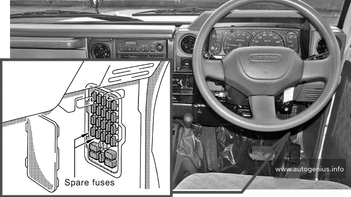
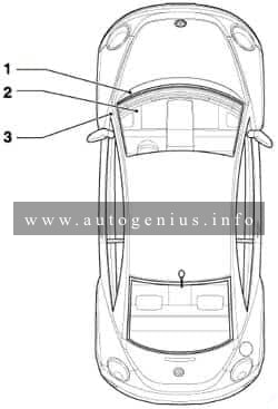
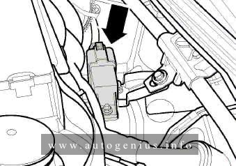
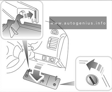
Fuse box location
The fuse panel is located behind the cover on the driver’s side of the instrument panel.
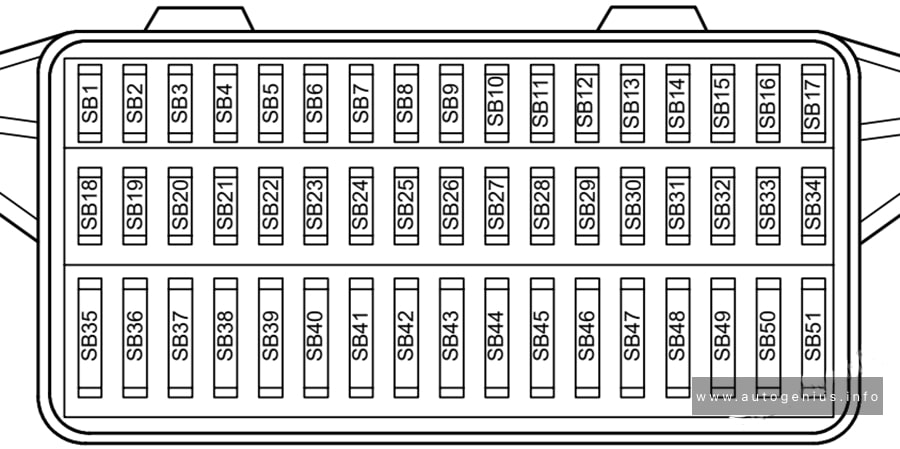
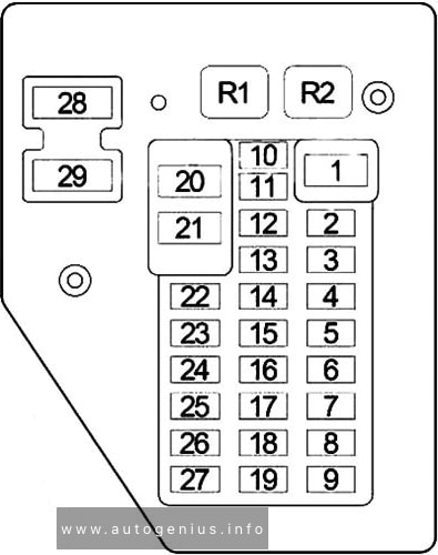
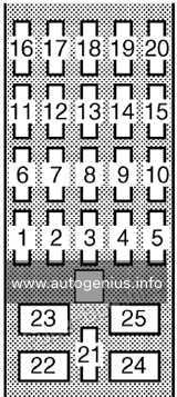
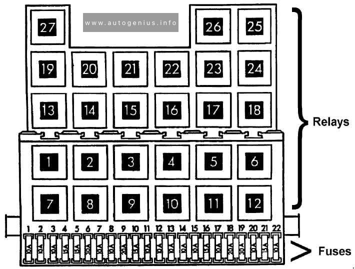
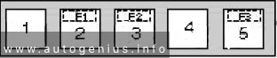
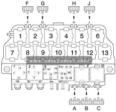
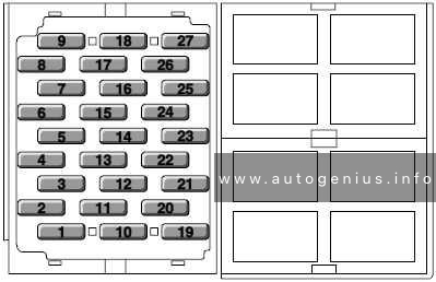
Fuse box diagram

Assignment of fuses in the passenger compartment (1998 – 2001)
| No. |
A |
Protected Component |
| 1 | 15 | Heated Seat Relay, Central Timer Module |
| 2 | 10 | Blower Motor Relay, A/C Heater Temperature Select, Blend Door Actuator, Driver Heated Seat Switch, Passenger Heated Seat Switch, Heated Mirror Switch |
| 3 | 10 | Controller Antilock Brake (ABS) |
| 4 | 10 | Radio Choke Relay |
| 5 | 5 | Radio, Cluster, A/C Heater Control, Cup Holder Lamp, Ash Receiver Lamp, Driver Heated Seat Switch, Passenger Heated Seat Switch |
| 6 | 25 | Intermittent Wiper Switch, Central Timer Module, Windshield Washer Pump, Wiper Motor, Wiper Motor Relay |
| 7 | 10 | Park/Neutral Position (PNP) Switch (A/T), Back-Up Lamp Switch (M/T), Daytime Running Lamp Module |
| 8 | 10 | Radio |
| 9 | 10 | Powertrain Control Module, Fuel Pump Relay (Gasoline), Engine Control Module (Diesel) |
| 10 | 10 | Combination Flasher |
| 11 | 10 | Automatic Day/Night Mirror, Overhead Console, Central Timer Module, EVAP/Purge Solenoid, Fuel Heater Relay (Diesel), Air Conditioner Compressor Clutch |
| 12 | 10 | Power Mirror Switch, Dome Lamp, Cargo Lamp, Data Link Connector, Radio, Glove Box Lamp and Switch, Overhead Console, Underhood Lamp, Left Visor/Vanity Lamp, Right Visor/Vanity Lamp |
| 13 | 10 | Driver Door Window/Lock Switch, Passenger Door Window/Lock Switch, Central Timer Module |
| 14 | 10 | Cluster |
| 15 | 20 | Cigar Lighter |
| 16 | – | – |
| 17 | 10 | Cluster |
| 18 | 10 | Airbag Control Module |
| 19 | 10 | Airbag Control Module, Passenger Airbag On/Off Switch |
| 20 | 20 | Circuit Breaker: Driver Door Window/Lock Switch, Passenger Door Window/Lock Switch |
| 21 | 20 | Circuit Breaker: Driver Power Seat Switch, Passenger Power Seat Switch |
| Relay | ||
| R1 | Combination Flasher | |
| R2 | Heated Seat | |
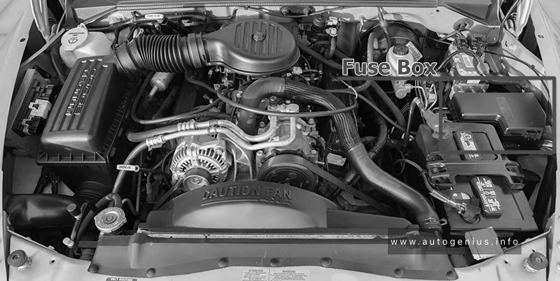
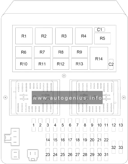
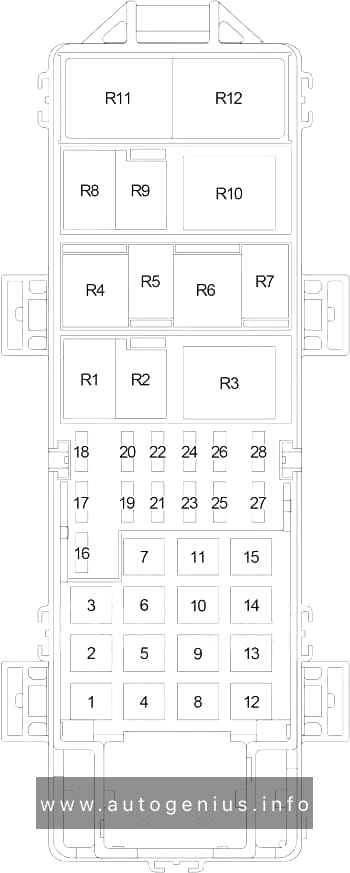
Engine Compartment Fuse Box
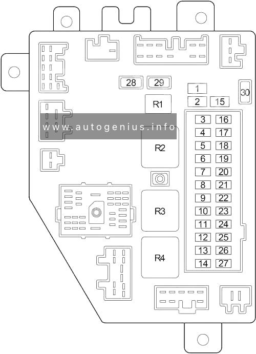
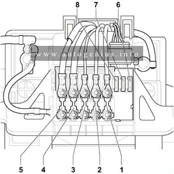
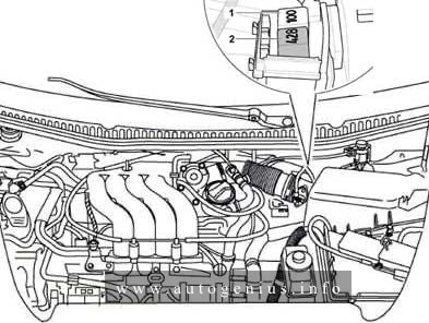
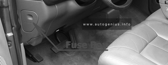
Fuse box location
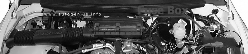
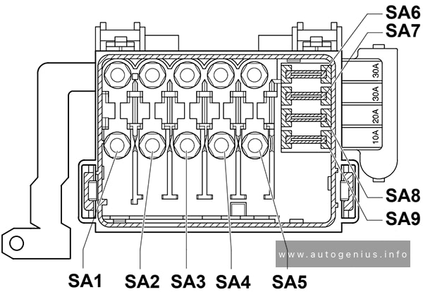
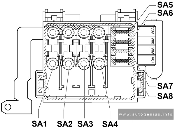
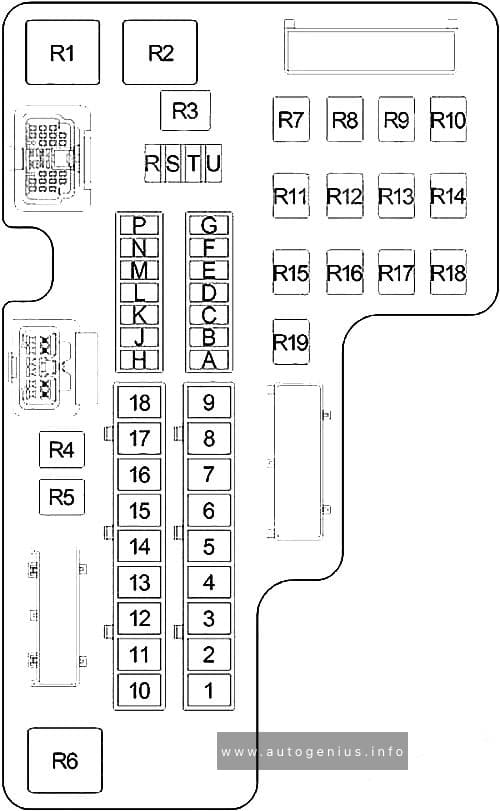
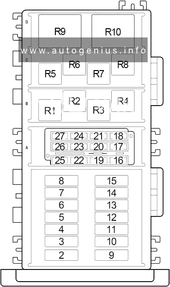
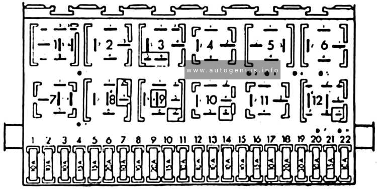
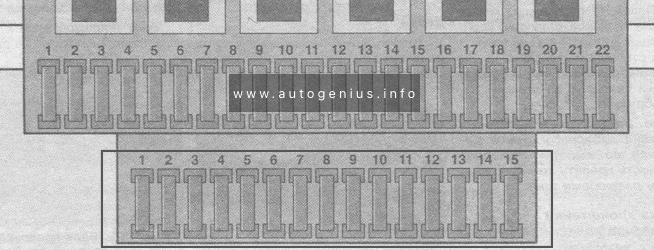
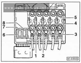
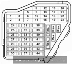
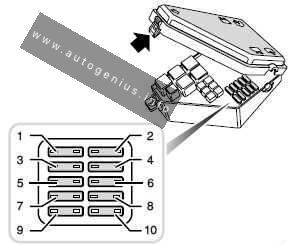
Fuse box diagram
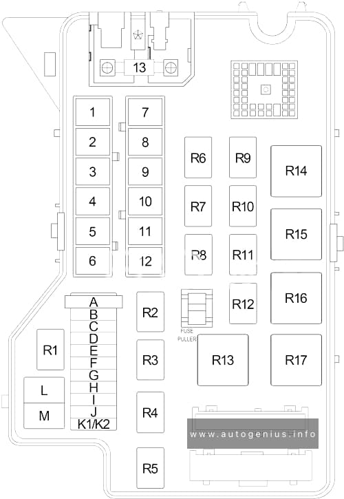
Assignment of fuses and relay in the engine compartment (1998 – 2001)
| No. |
A |
Protected Component |
| 1 | 50 | Junction Block ((Passenger Compartment) Fuse: “1”, “4”, “12”, “13”, “14”, “21”) |
| 2 | 30 | Ignition Switch |
| 3 | 20 | Gasoline: Powertrain Control Module, Fuel Pump Relay |
| 20 | Diesel: Engine Control Module, Powertrain Control Module, Fuel Pump Relay, | |
| 4 | 20 | Junction Block ((Passenger Compartment) Combination Flasher) |
| 5 | 20 | Stop Lamp Switch, Electric Brake Provision, Center High Mounted Stop Lamp, Turn Signal/Hazard Switch |
| 6 | 30 | Automatic Shut Down Relay, Injector, Ignition Coil, Capacitor, Oxygen Sensor, Oxygen Sensor Downstream Relay, Powertrain Control Module |
| 7 | 40 | Fuel Heater Relay |
| 8 | 40 | Trailer Tow Connector, Electric Brake Provision, Trailer Tow Relay |
| 9 | 30 | Starter Motor Relay |
| 10 | 50 | Ignition Switch |
| 11 | 40 | Controller Antilock Brake (ABS) |
| 12 | 40 | Blower Motor Relay |
| 13 | 140 | Generator |
| A | – | – |
| B | 15 | Right Outboard Headlamp |
| C | 15 | Left Outboard Headlamp |
| D | – | – |
| E | 15 | Left Headlamp, Right Headlamp, Quad High Beam Relay |
| F | 20 | Headlamp Switch |
| G | 15 | Security Relay, Daytime Running Lamp Module, Fog Lamp Relay, Headlamp Beam Select Switch, Left Outboard Headlamp, Right Outboard Headlamp |
| H | 20 | Horn Relay, Central Timer Module, Clockspring |
| I | 20 | Transmission Control Relay |
| J | 10 | Air Conditioner Compressor Clutch |
| K1 | 15 | |
| K2 | 15 | |
| L | 20 | Power Outlet |
| M | – | – |
| Relay | ||
| R1 | Fuel Pump | |
| R2 | – | |
| R3 | Horn | |
| R4 | Quad High Beam | |
| R5 | Fog Lamp | |
| R6 | Oxygen Sensor – Rear | |
| R7 | Wiper Motor | |
| R8 | Security | |
| R9 | ASD | |
| R10 | Air Conditioner Compressor Clutch | |
| R11 | – | |
| R12 | Transmission Control | |
| R13 | – | |
| R14 | Fuel Heater | |
| R15 | Starter Motor | |
| R16 | Blower Motor | |
| R17 | Trailer Tow | |
WARNING: Terminal and harness assignments for individual connectors will vary depending on vehicle equipment level, model, and market.