| № |
Amps |
Function/component |
|
|
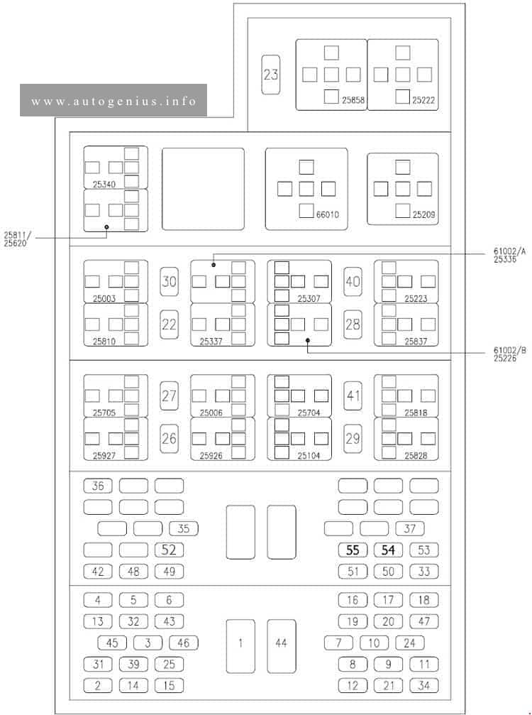
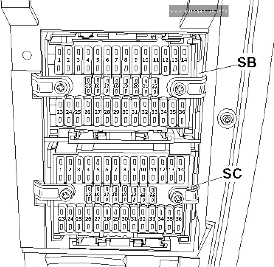
Fuse holder B |
| SB1 |
25A |
Fresh air blower isolation relay |
| SB1 |
30A |
2003:
Rear blower Bitron regulation motor
Fresh air blower isolation relay
X-contact relay
2004-2009:
Rear blower Bitron regulation motor |
| SB2 |
5A |
Steering angle sender |
| SB3 |
10A |
Onboard power supply control unit |
| SB4 |
10A |
Headlight range control regulator
Left headlight range control motor
Right headlight range control motor |
| SB5 |
15A |
Left headlight twin filament bulb
Left headlight dipped beam bulb
Special vehicle fuse 3 |
| SB6 |
15A |
Left headlight twin filament bulb
Left main beam bulb
Special vehicle fuse 6 |
| SB7 |
15A |
Onboard power supply control unit (interior light) |
| SB8 |
5A |
16-pin connector, diagnostic connector |
| SB9 |
10A/15A |
Brake light switch |
| SB10 |
5A/10A |
Intermittent wiper switch
Rear wiper switch |
| SB11 |
5A |
Number plate light
Switches and instruments illumination regulator (2003) |
| SB12 |
15A |
Cigarette lighter |
| SB13 |
5A |
2003-2004: Brake light additional relay
2004-2009: Airbag control unit |
| SB14 |
30A |
2003-2006:
Fresh air blower switch
Air conditioning system switch
Auxiliary coolant heater relay
Front blower Bitron regulation motor
2008-2009:
Headlight dipper/flasher switch |
| SB15 |
7,5A |
Air conditioning system switch
Fresh air/air recirculation flap switch (2004-2009)
Rear fresh air blower switch (2004-2009)
Climatronic control unit
Air conditioning system compressor regulating valve |
| SB16 |
5A |
Onboard power supply control unit |
| SB17 |
5A |
Rear fog light cut-out contact switch
Rear fog light warning lamp
Rear left fog light bulb
Trailer socket |
| SB18 |
5A |
Control unit in dash panel insert |
| SB19 |
5A |
Operating and display unit for camping equipment
Control unit in dash panel insert
Control unit with display for radio and navigation system
Onboard power supply control unit
Roof hydraulics control unit
Radio
Special vehicle fuse 1 |
| SB20 |
5A |
Left side light bulb
Left tail light bulb
Left brake and tail light bulb
10-pin connector, purple
Trailer socket |
| SB21 |
5A |
Right tail light bulb
Right side light bulb
Right brake and tail light bulb
Trailer socket |
| SB22 |
7,5A/10A |
Control unit in dash panel insert
Front passenger side airbag deactivated warning lamp
16-pin connector, diagnostic connector
16-pin connector, diagnostic connector 2 |
| SB23 |
25A/30A/40A |
Starter |
| SB23 |
5A |
Starter inhibitor relay, 10-pin connector, yellow |
| SB23 |
25A |
Trailer socket (2003) |
| SB24 |
5A |
Steering angle sender |
| SB25 |
5A |
Air conditioning system switch
Fresh air/air recirculation flap switch
Climatronic control unit |
| SB26 |
30A |
Lighting switch |
| SB27 |
15A |
Right headlight twin filament bulb
Right headlight dipped beam bulb
Special vehicle fuse 4 |
| SB28 |
15A |
Main beam warning lamp
Right headlight twin filament bulb
Right main beam bulb
Special vehicle fuse 7 |
| SB29 |
10A |
2004-2009: Dual signal inverter relay |
| SB30 |
10A |
Rear window wiper motor
Rear left wing door window wiper motor
Rear right wing door window wiper motor
Left washer jet heater element
Right washer jet heater element |
| SB31 |
30A |
Onboard power supply control unit (signal horn) |
| SB32 |
25A |
Onboard power supply control unit (windscreen wiper motor) |
| SB33 |
15A |
Control unit with display for radio and navigation system
Traffic information control unit
Radio |
| SB34 |
25A |
2003:
Speedometer sender
Air mass meter
Automatic gearbox relay
Engine control unit
2004-2009:
Automatic gearbox relay
Positive connection 1 (15), in engine harness
Fuses on fuse holder D (engine compartment): №3, 12, 14, 15, 16, 17, 19, 20, 24 |
| SB35 |
5A |
Instruments illumination |
| SB36 |
25A |
Onboard power supply control unit (turn signal) |
|
|
Fuse holder C |
| SC1 |
25A/15A |
2003: 12V socket 2
2004-2009: Trailer socket |
| SC2 |
5A |
Interior monitor send and receive module (2003)
Interior monitor send and receive module 2
Anti-theft and tilt system control unit (2004-2009) |
| SC3 |
5A |
2003-2007:
Right auxiliary blower
Left auxiliary blower |
| SC3 |
30A |
2008-2009: Onboard power supply control unit (heated rear window |
| SC4 |
10A/15A |
2003:
12V socket 3
2004-2006:
Four-wheel drive control unit
2007-2009:
Rear differential lock switch
Differential lock control unit
Four-wheel drive control unit |
| SC5 |
10A/15A |
2003: Refrigerator box
2004-2009: 6-pin connector, grey |
| SC6 |
5A |
Oil level and oil temperature sender |
| SC7 |
10A |
2003: Switch-over relay 1 for roof ventilator
2004-2009: Positive connection -6- (30), in main wiring harrness (roof ventilator) |
| SC7 |
15A |
2005-2009: 12V socket 4 |
| SC8 |
5A |
Parking aid control unit |
| SC9 |
5A |
Multifunction steering wheel control unit |
| SC10 |
30A |
Amplifier |
| SC11 |
15A |
2004-2009: Rear lid control unit |
| SC11 |
20A |
Alarm horn (2004-2009)
Convenience system central control unit
Left sliding door control unit
Rear lid control unit
Right sliding door control unit |
| SC12 |
5A/10A |
2003:
Auxiliary coolant heater relay
Brake light additional relay
2004-2009:
Brake light additional relay |
| SC13 |
5A |
Cruise control system switch
Operating unit in steering wheel
Airbag coil connector and return spring with slip ring |
| SC14 |
5A |
Mobile telephone operating electronics control unit |
| SC15 |
5A |
Gearshift indicator control unit |
| SC16 |
5A |
Control unit with display for radio and navigation system
Mobile telephone operating electronics control unit (2004-2006) |
| SC17 |
5A/7,5A |
Onboard power supply control unit (interior light)
Positive connection -1- (30), in main wiring harrness
Rear Climatronic operating and display unit (2003-2004) |
| SC18 |
5A |
Rear fresh air blower switch |
| SC18 |
5A |
2004-2009: Rear Climatronic operating and display unit |
| SC19 |
5A |
Automatic anti-dazzle interior mirror |
| SC20 |
10A |
Onboard power supply control unit (heated exterior mirror) |
| SC21 |
5A |
2003: Interior monitor send and receive module 1
2004-2009: Anti-theft and tilt system control unit |
| SC22 |
5A |
High-pressure sender
Air quality sensor |
| SC23 |
5A/10A |
Operating and display unit for camping equipment
Auxiliary heater operating and display unit
Residual heat relay
Remote control receiver for auxiliary coolant heater |
| SC24 |
5A/7,5A |
2003-2004: Operating and display unit for camping equipment
2004-2009: Positive connection in roof wiring harness (interior lighting) |
| SC25 |
15A/25A |
Heated driver seat regulator
Heated front passenger seat regulator
Heated front seats control unit
Heated front passenger control unit
Front passenger seat temperature sensor (2003) |
| SC26 |
10A |
Tachograph (models with tachograph) |
| SC26 |
15A |
2004-2009: 12V socket 2 (Multivan without tachograph and second battery) |
| SC27 |
15A |
Left fog light bulb
Right fog light bulb
Special vehicle fuse |
| SC28 |
5A |
Mirror adjustment switch
Driver door control unit (2006-2009) |
| SC29 |
25A |
Auxiliary heater control unit |
| SC30 |
5A |
Operating and display unit for camping equipment |
| SC30 |
5A |
Auxiliary coolant heater relay |
| SC31 |
25A |
Sliding sunroof adjustment control unit |
| SC31 |
5A |
2006-2009: Onboard supply charger unit (camper only) |
| SC32 |
20A |
Headlight washer system relay |
| SC33 |
5A |
Tachograph (models with tachograph) |
| SC33 |
15A |
Tachograph (models with tachograph)
Folding exterior mirror control unit (models with tachograph and electric folding exterior mirror) |
| SC33 |
15A |
Folding exterior mirror control unit (2006-2009) |
| SC34 |
10A/15A/20A/25A |
2003:
Vacuum pump for brakes
2004: Trailer socket
2004-2009:
12V socket 3 |
| SC35 |
10A |
Onboard supply control unit (reversing light models with automatic gearbox) |
| SC36 |
5A/15A |
2003-2004:
12V socket 4
2004-2009:
Operating and display unit for camping equipment
10-pin connector, purple (models with electric interface only (UF1)) |