Dodge Ram 5500 Chassis Cab (2018 – 2024) – fuse box diagram
Year of production: 2018. 2019, 2020, 2021, 2022, 2023, 2024
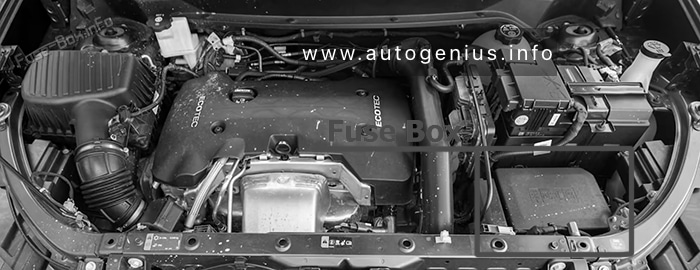
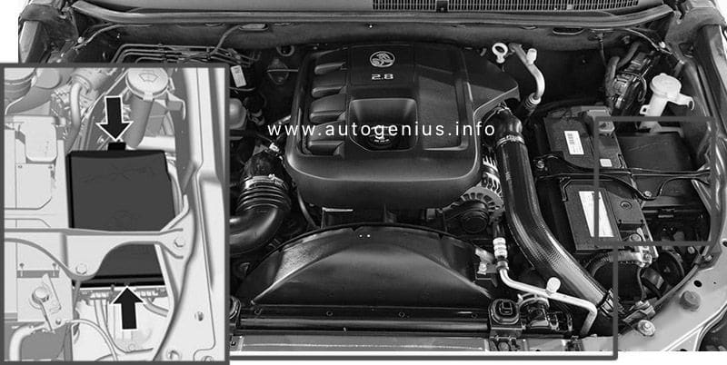
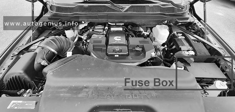
Engine Compartment
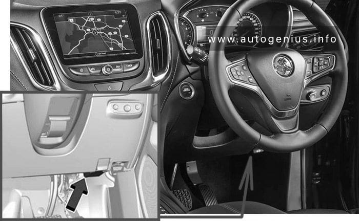
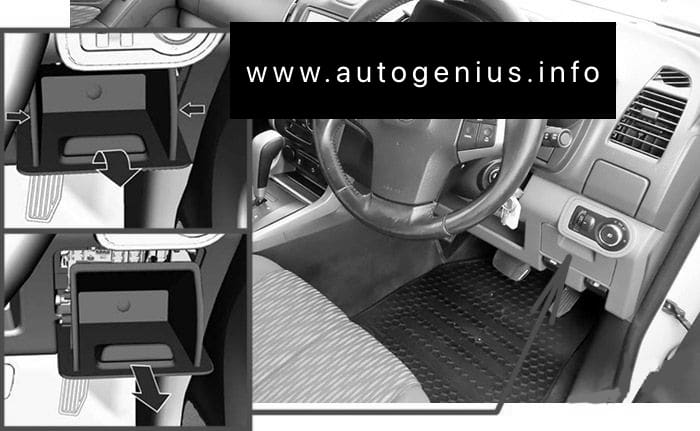
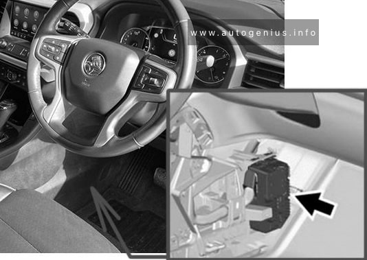
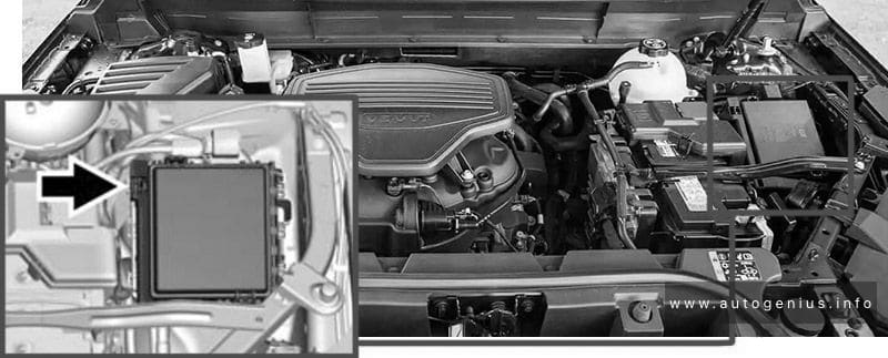
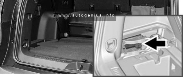
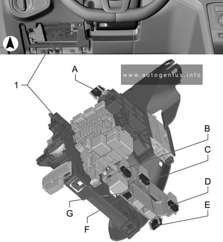
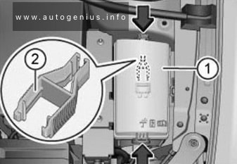
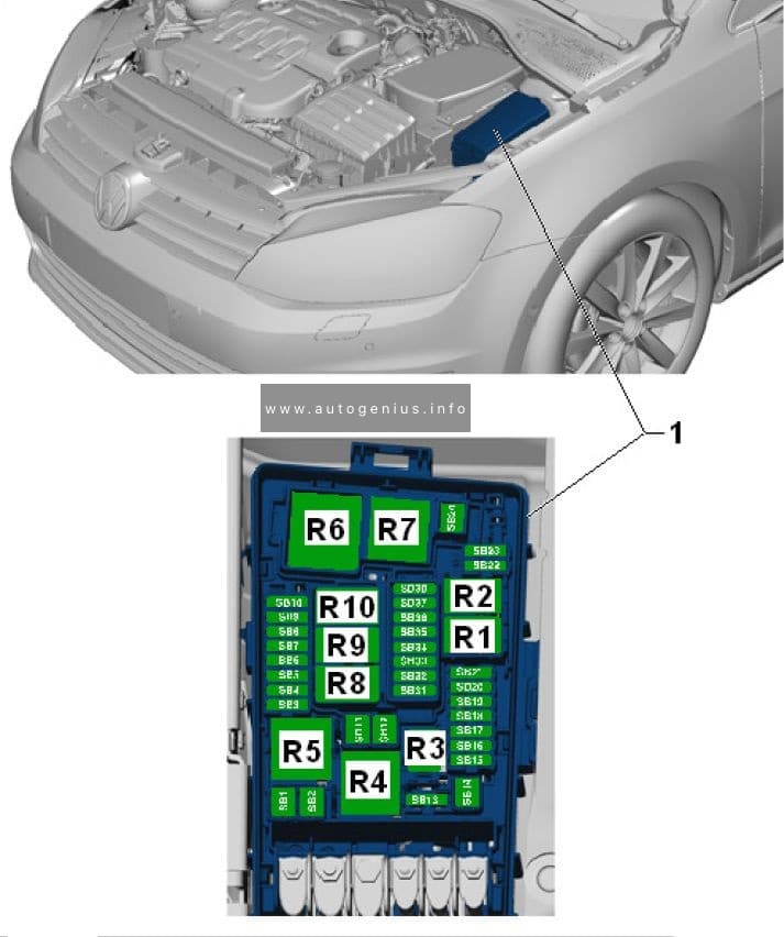
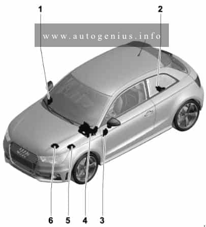
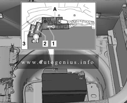
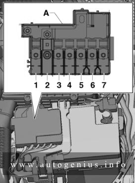
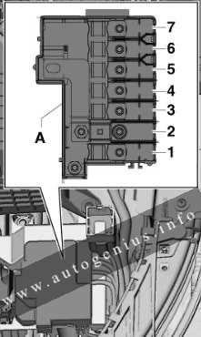
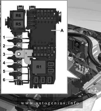
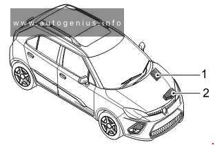
Fuse Box Location
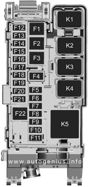
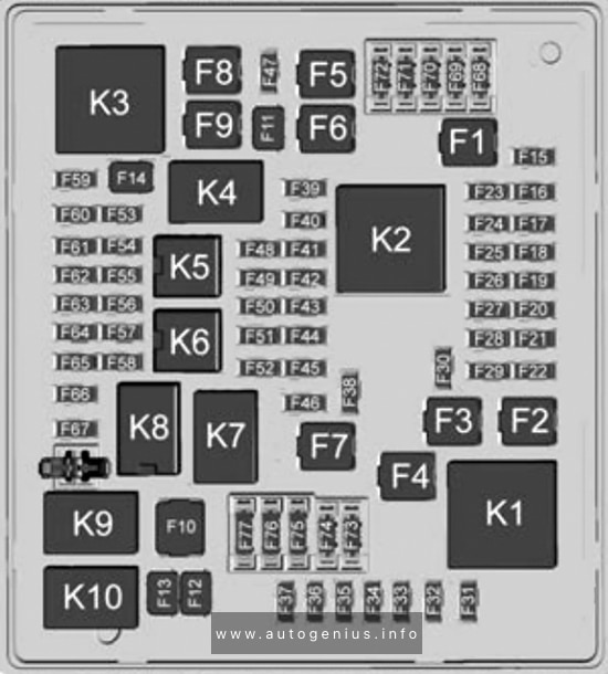
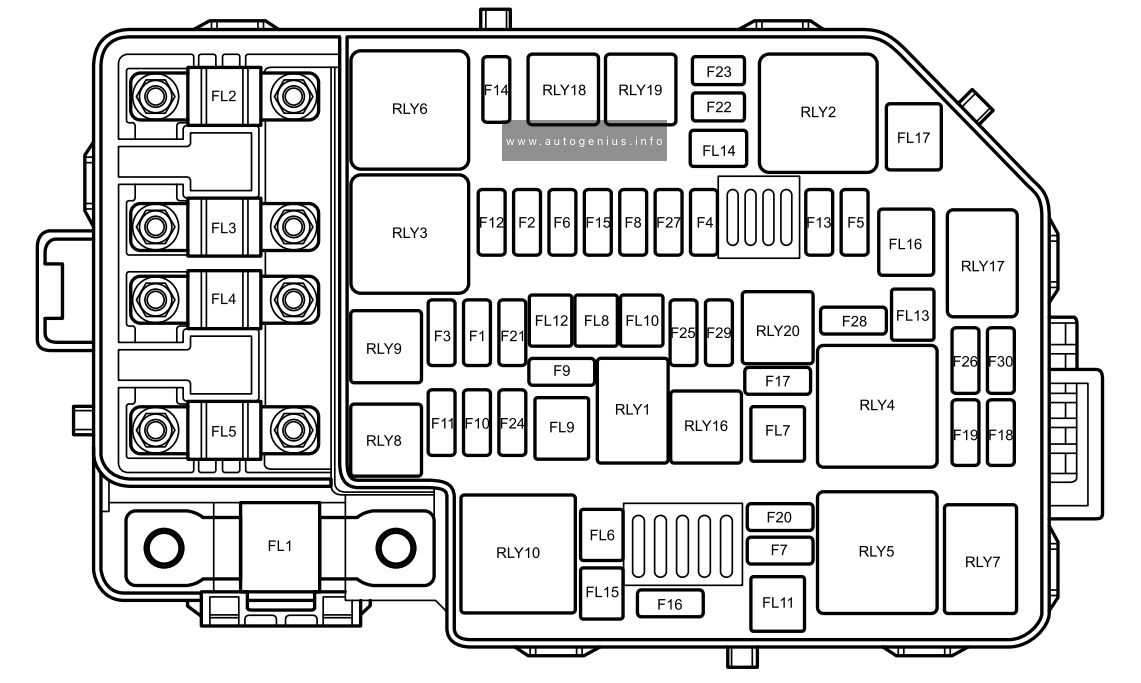
The Power Distribution Center is located in the engine compartment near the battery. This center contains cartridge fuses, micro fuses, relays, and circuit breakers. A description of each fuse and component may be stamped on the inside cover, otherwise the cavity number of each fuse is stamped on the inside cover.
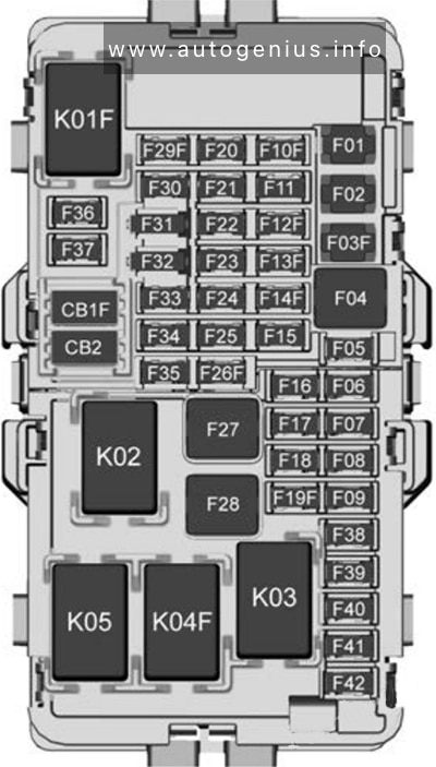
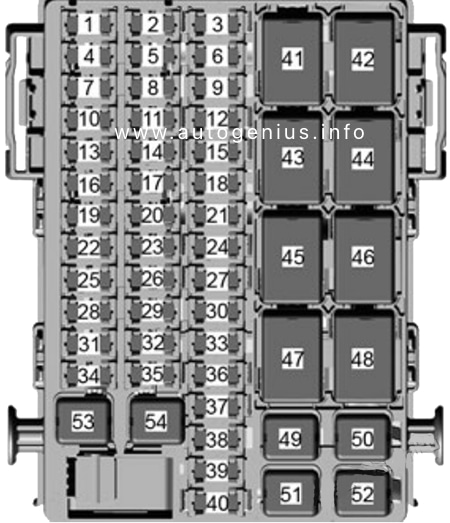
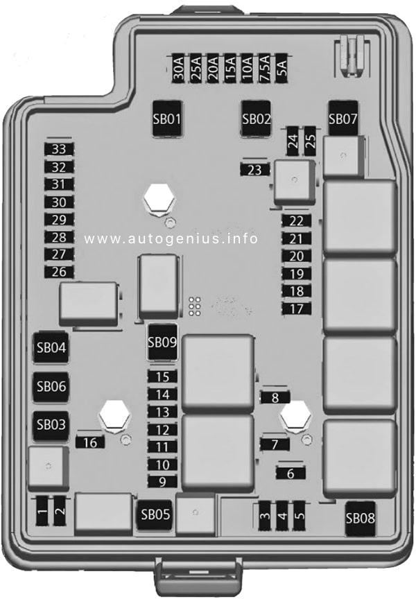
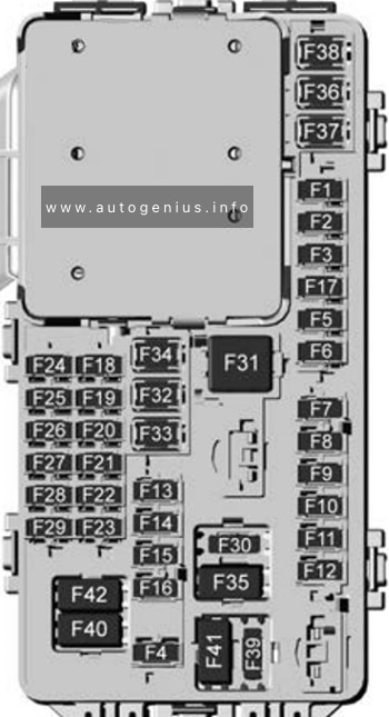
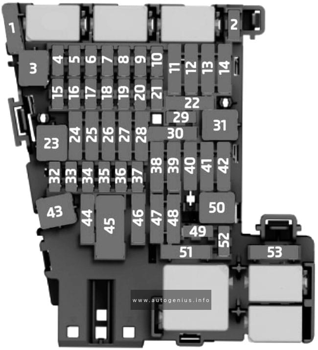
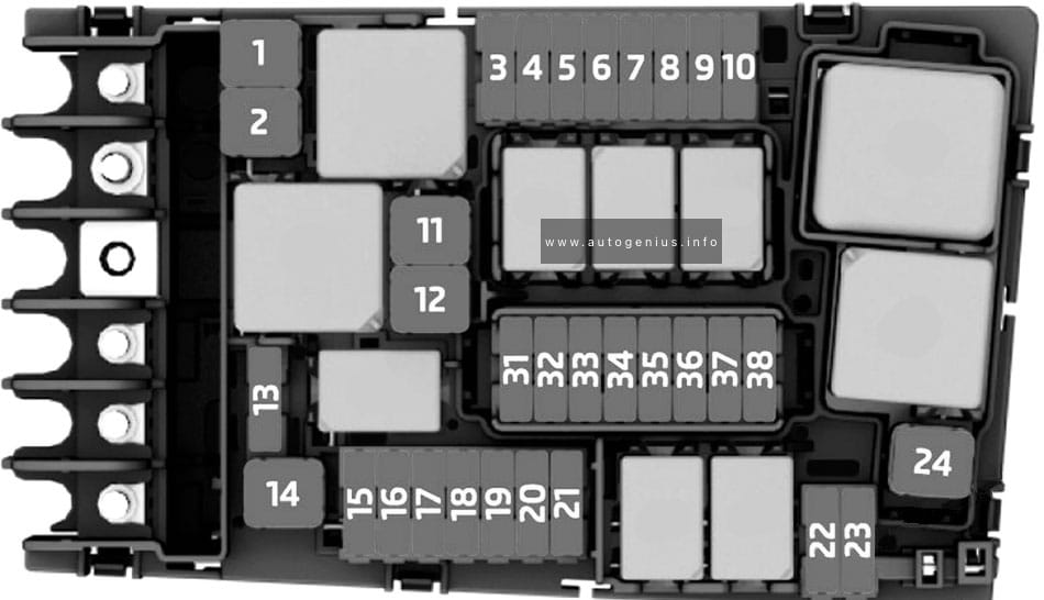
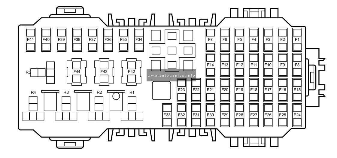
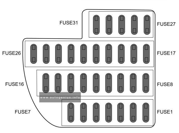
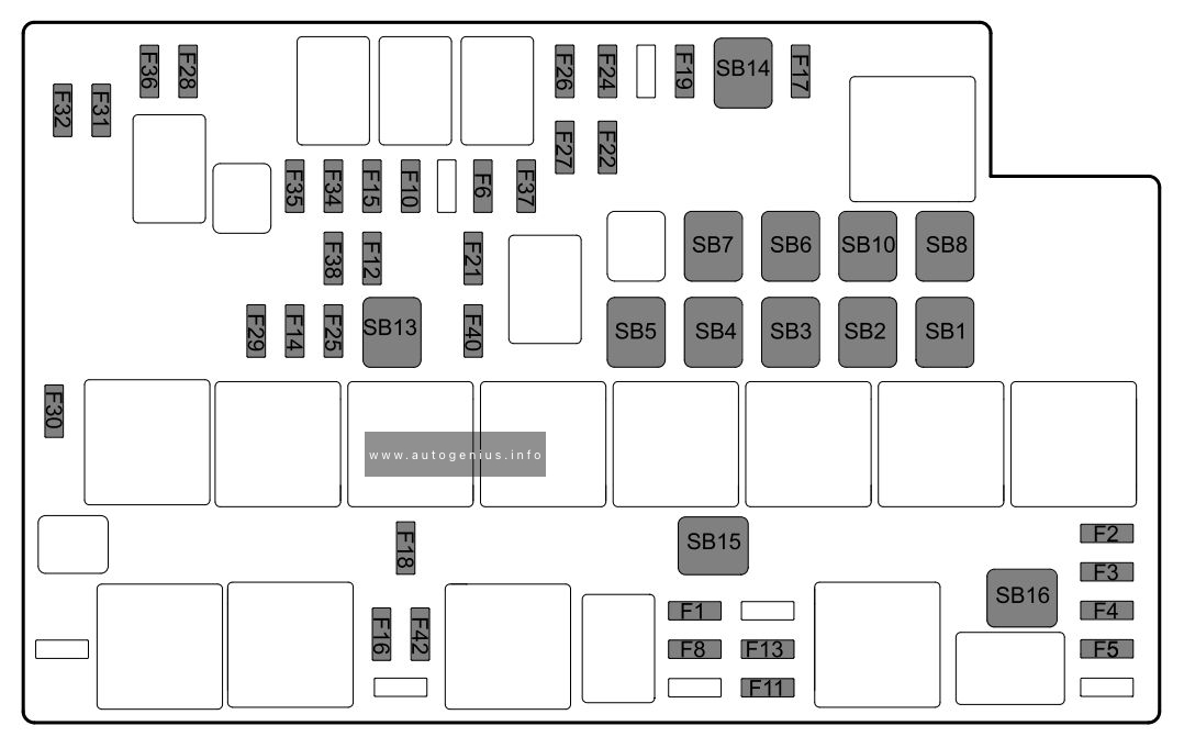
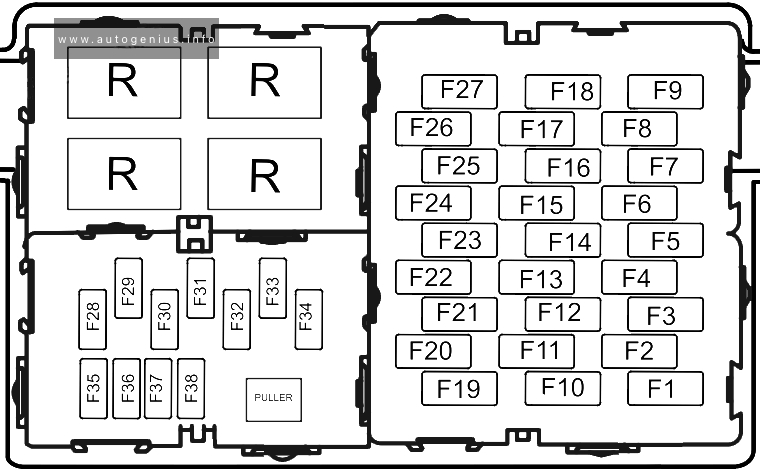
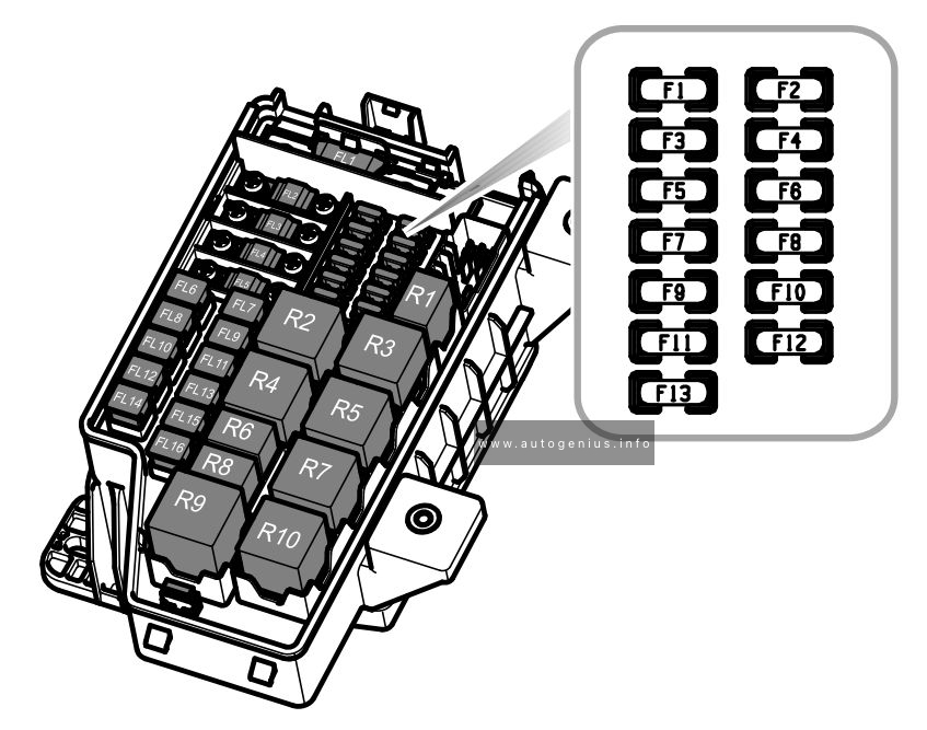
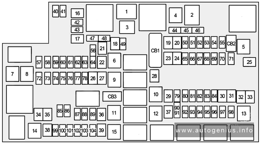
Fuse box diagram (Power Distribution Center)
| № | Cartridge Fuse | Micro Fuse | Description |
|---|---|---|---|
| F01 | 80A Black | 2018-2018: Rad Fan Control Module – If Equipped (DS 1500 Only) 2019-2024: Spare |
|
| F02 | 60A Yellow | 2018-2021: ABS Pump Motor (HD Only) 2022-2024: ABS Pump Mtr |
|
| F03 | 60A Yellow | Rad Fan HI/Lo (if Equipped) | |
| F04 | 50A Red | 2019-2024: 400W Inverter | |
| F05 | 40A Green / 50A Red | Air Suspension Comp | |
| F06 | 40A Green | 2018: Antilock Brakes / Electronic Stability Control Pump 2019: ABS Pump Motor (DS 1500 Only) 2020-2024: Steering Torque Overlay Module (STOM) |
|
| F07 | 40A Green | Starter Solenoid | |
| F08 | 20A Blue | 2018: Emissions Diesel – If Equipped 2019: NOX Sensor – If Equipped; Aux Relay Output – SSV Only 2020-2024: NOX Sensor (if Equipped) |
|
| F09 | 30A Pink / 40A Green | 2018: Diesel Fuel Heater – If Equipped 2019: Aux Relay Output / Diesel Fuel Heater – If Equipped 2020-2024: Gas – Brake Vacuum Pump (if Equipped) / Diesel – Fuel Heater (if Equipped) |
|
| F10 | 40A Green / 50A Red | Body Controller / Exterior Lighting #2 | |
| F11 | 30A Pink / 40A Green | 2018: Integrated Trailer Brake Module – If Equipped 2019-2024: Brake System Module (ECU and Valves) |
|
| F12 | 40A Green | Body Controller #3 / Power Locks | |
| F13 | 40A Green | HVAC Blower Motor | |
| F14 | 40A Green | Body Controller #4 / Exterior Lighting | |
| F15 | 30A Pink | 2019-2024: Power Side Step (if Equipped) | |
| F16 | 30A Pink | Smart-Bar Module (if Equipped) | |
| F17 | 30A Pink | 2019-2024: Winch Control Module – If Equipped | |
| F18 | Spare | ||
| F19 | 20A Blue / 30A Pink | Diesel SCR Feed (if Equipped) | |
| F20 | 30A Pink | Passenger Door Mod | |
| F21 | 30A Pink | Drive Train Control Module | |
| F22 | 20A Blue / 25A White / 30A Pink | 2018: Engine Control Module 2019: Engine Control Module GPEC / Heavy Duty / Other – If Equipped 2020-2024: Gas – ECM (if Equipped) / Diesel – PCM (if Equipped) |
|
| F23 | 30A Pink | Body Controller #1 / Interior Lighting | |
| F24 | 30A Pink | Driver Door Mod | |
| F25 | 30A Pink | Front Wiper | |
| F26 | 30A Pink | 2018-2019: Antilock Brakes / Stability Control Module / Valves – If Equipped 2020-2024: Spare |
|
| F27 | Spare | ||
| F28 | 20A Blue | Trailer Tow Backup Lights – If Equipped | |
| F29 | 20A Blue | Trailer Tow Parking Lights – If Equipped | |
| F30 | 30A Pink | 2018: Trailer Tow Receptacle 2019-2021: Trailer Tow Receptacle / Trailer Tow (Separate E-Brake) / Trailer Tow (BUX) 2022-2024: Trailer Tow |
|
| F31 | 30A Pink | 2018: Urea Heater Control – If Equipped 2019: Diesel Heater Control – If Equipped (DS 1500 LD Diesel) 2020-2024: Spare |
|
| F32 | Spare | ||
| F33 | 20A Blue | 2018: Special Services Vehicle Only 2019-2024: Transmission Control Module (if Equipped) |
|
| F34 | 30A Pink | Vehicle System Interface Module #2 (if Equipped) | |
| F35 | 30A Pink | Sunroof (if Equipped) | |
| F36 | 30A Pink | Rear Defroster (EBL) (if Equipped) | |
| F37 | 30A Pink | 2018: Cummins Diesel Fuel Heater #2 (If Equipped) 2019: Fuel Heater #2, Aux Relay 2 – If Equipped (HD Only); SSV (DS 1500 Only) 2020-2024: Diesel Frame / Fuel Heater (if Equipped) |
|
| F38 | 30A Pink | 2018: Power Inverter 115V AC (If Equipped) 2019: Integrated Trailer Brake Module – If Equipped (HD Only); Power Inverter 115V AC – If Equipped (DS 1500 Only) 2020-2024: Integrated Trailer Brake Module (if Equipped) |
|
| F39 | 20A Blue | 2018-2019: Power Outlet – Special Services Only 2020-2024: Spare |
|
| F40 | 10A Red | 2019-2024: Ventilated Seats (if Equipped) | |
| F41 | 10A Red | 2018: Active Grille Shutter (If Equipped) 2019-2024: Active Grille Shutter / Active Air Dam (if Equipped) |
|
| F42 | 20A Yellow | Horn | |
| F43 | 15A Blue | 2019-2024: Heated Steering Wheel (if Equipped) | |
| F44 | 10A Red | Diagnostic Port | |
| F45 | Spare | ||
| F46 | 10A Red | Upfitters Relay Coils (if Equipped) | |
| F47 | Spare | ||
| F48 | Spare | ||
| F49 | 10A Red / 15A Blue | 2018: Instrument Panel Cluster (Except Fleet Vehicles) 2019: Instrument Panel Cluster / HVAC (DS 1500 Only); Instrument Cluster / MOD CSG (HD Only) 2020-2024: IP Cluster / CSG |
|
| F50 | 20A Yellow | Air Suspension Control Module (if Equipped) | |
| F51 | 10A Red | 2018-2021: Ignition Node Module / Keyless Ignition Node Module, Radio Frequency Hub Module / Electric Steering Column Lock 2022-2024: Ignition Node Module / Keyless Ignition Node Module, Radio Frequency Hub Module |
|
| F52 | 5A Tan | Battery Sensor | |
| F53 | 20A Yellow | Trailer Tow – Left Turn/Stop Lights | |
| F54 | 20A Yellow | Non Memory Adjustable Pedals (if Equipped) | |
| F55 | 10A Red | 2023-2024: Fwd Utility Lamps | |
| F56 | 10A Red / 15A Blue | 2018-2019: Additional Diesel Content (If Equipped) 2020-2024: Fuel Vapor Blocking Valve (VBV) |
|
| F57 | 20A Yellow | TCM / PCM / Solenoid Trans Pressure SW | |
| F58 | 10A Red | 2019-2024: Bed Lighting (LED) | |
| F59 | Spare | ||
| F60 | 15A Blue | 2018: Underhood Lamp 2019: Underhood Lamp / TCM – If Equipped (DS 1500 Only) 2020-2024: Spare |
|
| F61 | 10A Red | 2018: PM Sensor (If Equipped) 2019: UREA Sensor / PM Sensor – If Equipped (DS 1500 LD Diesel & Cummins Diesel) 2020-2024: NH3 Sensor / PM Sensor (if Equipped) |
|
| F62 | 10A Red | Air Conditioning Clutch | |
| F63 | 20A Yellow | 2018: Ignition Coils (Gas), Urea Heater (Cummins Diesel) 2019: Ignition Coils (Gas), Ignition Coils Capacitors (Gas) / Short Runner Valve Actuator / Urea Heater Control Unit (DS 1500 LD Diesel) / RLY Coil Feed-SCR (DS 1500 LD Diesel) 2020-2024: Ignition Coils / CAPS |
|
| F64 | 25A Clear | Fuel Injectors / PCM (if Equipped) | |
| F65 | 10A Red | 2018: Spare 2019-2021: MOD Inverter (Wake Up) / Power Port / USB IP / WCPM – If Equipped (HD Only) 2022: Spare 2023-2024: RVDMP / MOD BLE (if Equipped) |
|
| F66 | 10A Red | 2018: Sunroof / Passenger Window Switches / Rain Sensor 2019: Sunroof / Light and Rain Sensor Module / Inside Rearview Mirror / Passenger Window SW / USB Port Rear / Feed for R/A RLY #2 Coil (If Equipped) 2020-2021: Sunroof / USB Rear (If Equipped) 2022-2024: Sunroof / USB Rear / Inside Rearview Mirror/ Passenger Window SW |
|
| F67 | 10A Red | 2018: CD / DVD / Bluetooth Hands-free Module (If Equipped) 2019: CD / DVD / UCI Port – If Equipped (HD Only); Bluetooth Hands-Free Module / CD – If Equipped (DS 1500 Only) 2020: CDM / UCI Port / USB Front 2021: UCI Port / USB Front 2022: UCI Port / USB Front / Trailer Gateway Module (360 Camera) / Tachograph 2023-2024: UCI Port / Trailer Gateway Module (360 Camera) / Tachograph |
|
| F68 | 10A Red | 2019-2024: AEB RACAM HTR (if Equipped) | |
| F69 | 15A Blue | SCR Mod 12 Volt (if Equipped) | |
| F70 | 30A Green | 2018: Fuel Pump Motor 2019-2021: Fuel Pump Motor / K09 RLY Coil Feed (If Equipped) 2022-2024: Fuel Pump Mtr / Fuel Htr RLY |
|
| F71 | 25A Clear | 2018: Amplifier 2019-2024: Amplifier / Active Noise Cancelation |
|
| F72 | 10A Red | 2018: PCM (If Equipped) 2019: PCM / DC/DC Converter Voltage – If Equipped (DS 1500 Only) 2020-2024: Spare |
|
| F73 | 20A Yellow | Fuel Transfer Pump (if Equipped) | |
| F74 | 20A Yellow / 10A Red | 2018-2019: Brake Vacuum Pump Gas/Diesel (If Equipped) 2020-2024: Backup Alarm |
|
| F75 | 10A Red | 2018: Coolant Temperature Valve Actuator 2019: ATMM / Coil-SCR Module RLY – If Equipped (HD Only); Coolant Temperature Valve – If Equipped (DS 1500 Only) 2020-2024: ATMM / Coil-SCR Module RLY (if Equipped) |
|
| F76 | 10A Red | 2018: Antilock Brakes / Electronic Stability Control 2019: Electronic Stability Control (HD Only); Brake System Module / Stop Lamp Switch / Electric Park Brake / Clutch Pedal Switch (DS 1500 Only) 2020-2024: Electronic Stability Control (ESC) (if Equipped) |
|
| F77 | 10A Red | 2018: Drivetrain Control Module / Front Axle Disconnect Module 2019: Drivetrain Control Module / Front Axle Disconnect Module / TCM (HD Only); Drivetrain Control Module / ELSD / Front Axle Disconnect Module / Transmission Control Relay / RDM / Power Take Off Unit – If Equipped (DS 1500 Only) 2020-2024: Drivetrain Control Module / Front Axle Disconnect Module / TCM / STOM |
|
| F78 | 10A Red / 15A Blue | 2018: Engine Control Module / Electric Power Steering 2019: Engine Control Module / Powertrain Control Module / AEB RACM MOD / Feed To AUX PDC Relay Coils (HD Only) 2020-2021: Engine Control Module / Powertrain Control Module / AEB RACM MOD / Feed To AUX PDC Relay Coils / HRLS 2022-2024: ECM / PCM / IRCM / AUX Relay Feed / HRLS |
|
| F79 | 15A Blue | 2018: Clearance Lights 2019-2024: ID / Clearance Lt |
|
| F80 | 10A Red | 2018: Universal Garage Door Opener / Compass 2019: Universal Garage Door Opener/Compass/Anti-Intrusion Module (DS 1500 Only); ASSY Overhead Console / SW Assist / SW 911 – If Equipped (HD Only) 2020-2024: Overhead Console / Assist / 911 |
|
| F81 | 20A Yellow | Trailer Tow Right Turn/Stop Lights | |
| F82 | 10A Red | Steering Column Control Module / Cruise Control | |
| F83 | 10A Red | 2023-2024: TLR AST / TLR RVS CTL / TLR KNB | |
| F84 | 15A Blue | 2018: Switch Bank / Instrument Cluster 2019-2024: ASBM / HVAC / ICS / Rear Heated Seat Switches |
|
| F85 | 10A Red | ORC (Airbag) | |
| F86 | 10A Red | ORC (Airbag) | |
| F87 | 10A Red | 2018: Air Suspension – If Equipped / Trailer Tow / Steering Column Control Module 2019: Air Suspension / ITBM / Steering Column Control Module / MOD Gateway CAN-C Trailer TPM (HD Only); Air Suspension / Trailer Tow / DC/DC Converter (Voltage Stabilizer) / Steering Column Control Module / Occupant Classification Sensor (DS 1500 Only) 2020-2021: Air Suspension / ITBM / Steering Column Control Module / MOD Gateway CAN-C Trailer TPM 2022-2024: Air Susp / ITBM / SCCM / TLR TPM |
|
| F88 | 15A Blue | Instrument Panel Cluster | |
| F89 | Spare | ||
| F90 | 20A Yellow | Power Outlet / Batt (Customer Selectable) | |
| F91 | 20A Yellow | Power Outlet / Acc (Customer Selectable) | |
| F92 | 10A Red | 2023-2024: Invertor MOD / USB-IP / WCPM (if Equipped) | |
| F93 | 20A Yellow | 2018-2019: Cigar Lighter | |
| F94 | 10A Red | 2018: Shifter / Transfer Case Module 2019: Shift-By-Wire / Transfer Case Switch (DS 1500 Only); Shift-By-Wire/Transfer Case Switch / Module TPM Trailer (HD Only) / Module Gateway Can-C Trailer TPM (HD Only) 2020-2022: Shift-By-Wire / Transfer Case Switch / Module TPM Trailer / Module Gateway Can-C Trailer TPM 2023-2024: SBW / TCASE SW / TRL TPM – GTWY |
|
| F95 | 10A Red | 2018: Rear Camera / Park Assist 2019: Rearview Camera / Park Assist / CHMSL Camera / Blind Spot Sensor / Surround View Camera (HD Only) Rear Camera / Park Assist/ Blind Spot Sensor / Compass (DS 1500 Only) 2020-2024: Rearview Camera / Park Assist / CHMSL Camera / Blind Spot Sensor / Surround View Camera |
|
| F96 | 10A Red | 2018: Rear Seat Heater Switch 2019: Rear Seat Heater Switch / Trunk Lamp With Flashlamp Charger / Truck Lamp – If Equipped (DS 1500 Only); Trailer Camera – If Equipped (HD Only) 2020-2024: Trailer Camera (if Equipped) |
|
| F97 | 20A Yellow / 25A Clear | 2018-2019: Rear Heated Seats & Heated Steering Wheel (If Equipped) 2020-2024: Front Heated Seat Passenger (if Equipped) |
|
| F98 | 20A Yellow / 25A Clear | 2018-2019: Front Heated Seats (If Equipped) 2020-2024: Front Heated Seat Driver (if Equipped) |
|
| F99 | 10A Red | 2018: Climate Control 2019: HVAC / DASM (DS 1500 Only); HVAC/ In-Car Temperature Sensor / CSG MOD / Humidity Sensor (HD Only) 2020-2021: HVAC / In-Car Temperature Sensor / CSG MOD 2022-2024: HVAC / In-Car Temperature Sensor / CSG MOD / Module Gateway Trailer / Tachograph |
|
| F100 | 10A Red | Upfitter Box Feed (if Equipped) | |
| F101 | 20A Yellow | 2018: Electrochromatic Mirror / Smart High Beams (If Equipped) 2019: SSV Only 2020-2024: Rear Heated Seat Right (if Equipped) |
|
| F102 | 20A Yellow | 2019-2024: Rear Heated Seat Left / Run RLY #3 Coil (if Equipped) | |
| F103 | 10A Red | HeadLamp AFLS (if Equipped) | |
| F104 | 20A Yellow | 2018: Power Outlets (Instrument Panel / Center Console) 2019: Power Outlets (Instrument Panel / Center Console) / Trunk – If Equipped (DS 1500 Only); UCI Port / USB Rear (HD Only) 2020-2024: UCI Port / USB Rear |
WARNING: Terminal and harness assignments for individual connectors will vary depending on vehicle equipment level, model, and market.