Buick Century (V; 1995) – fuse and relay box diagram
Year of production: 1995
This article covers the Buick Century. It includes fuse box diagrams for the 5th generation 1995 models, provides details on the location of the fuse panels inside the vehicle, and explains the function and layout of each fuse.
Passenger compartment
Fuse box location
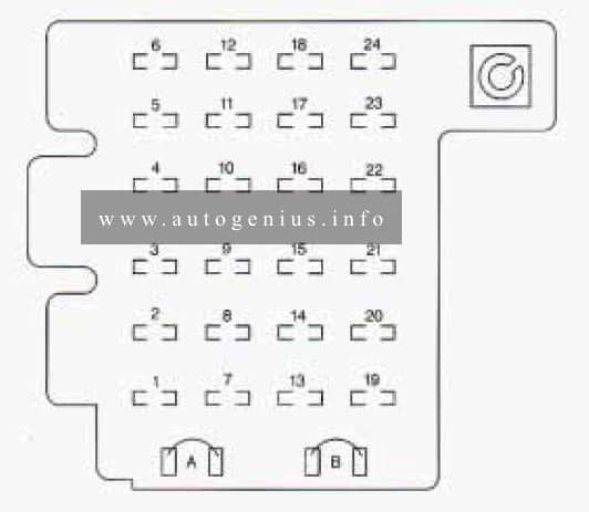
The fuse panel is located inside the glove box, on the left side.
Fuse box diagram
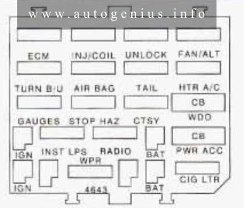
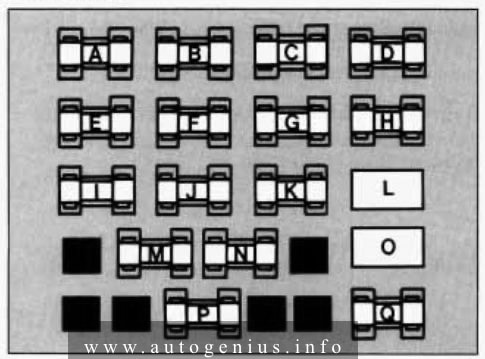
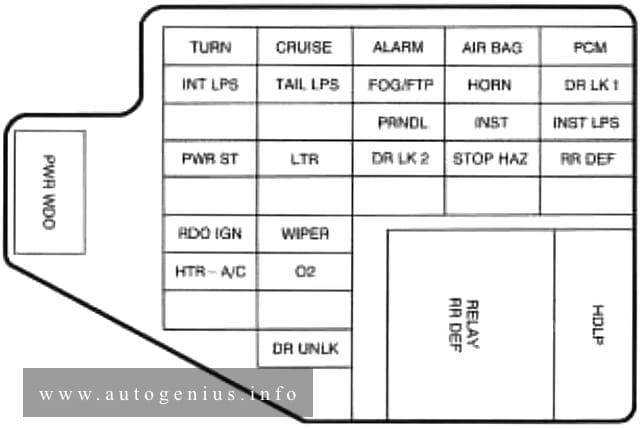
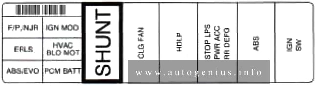
Assignment of the fuses in the passenger compartment (instrument panel)
| Fuse | Usage |
| ECM | Power Train Control Module |
| TNJ/COIL | Fuel Injectors |
| UNLOCK | Auto Door Locks (Remove this fuse to disable the automatic door unlock) |
| FAN/ALT | Electric Fan, Starter and Generator, Seq. Fuel Inj (V6), Cruise Control, Anti-Lock Brakes |
| TURN B/U | Back-up Lamps |
| AIR BAG | Supplemental Inflatable Restraint (Air Bag) |
| TAIL | Tail, Park. Side Marker, License Plate, Stop/Turn Signal |
| HTR A/C | Heater/Air Conditioner Blower Controls |
| GAUGES | I/P Cluster, Warning Indicators, Torque Converter Clutch, Audible Warning System, Trunk Release, Brake Warning Indicator, Rear Defog Switch, Remote Keyless Entry, Headlamps, Air Bag (DERM) |
| STOP HAZ | Stop Lamps, Hazard Flashers |
| CTSY | Interior, Underhood, Courtesy, UP, Trunk Lamps. Door Locks, Horn Relay, Passive Restraint System, Deck Lid Release, Power Antenna Remote Keyless Entry: Vanity Mirror |
| WDO | Power Windows |
| INST LPS | Illumination for: I/P, Radio, Pod Lamps, Ashtray, Console Lamp, Heater-A/C Control, Defog Switch, Headlamp Switch, Power Antenna, Lighted Vanity Mirrors |
| RADIO | Radio |
| PWR | Seats, Door Locks, Rear Defog. Power Seat |
| ACC* | Recliner, Rear Window Wiper, Trunk Release. |
| WPR | Windshield WiperWxher |
| CIG LTR | Cigarette Lighter |
| *Circuit Breaker | |
WARNING: Terminal and harness assignments for individual connectors will vary depending on vehicle equipment level, model, and market.