Buick Century (VI; 2000 – 2001) – fuse box diagram
Year of production: 2000, 2001
This article covers the Buick Century. It includes fuse box diagrams for the 6th generation 2000 and 2001 models, provides details on the location of the fuse panels inside the vehicle, and explains the function and layout of each fuse.
Passenger compartment
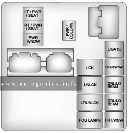
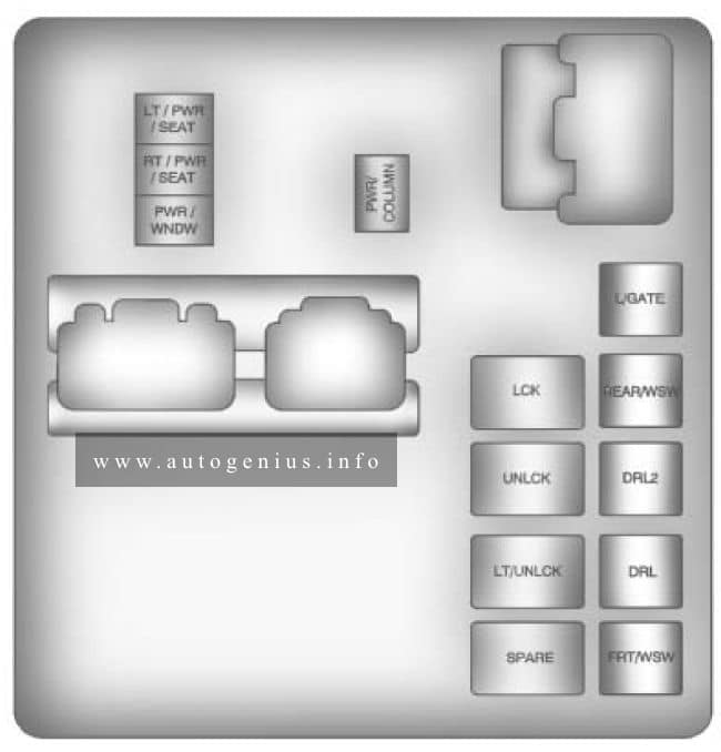
Fuse box location
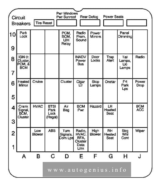
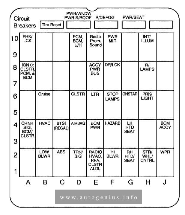
The fuse box is located on right side of the instrument panel, behind the cover.
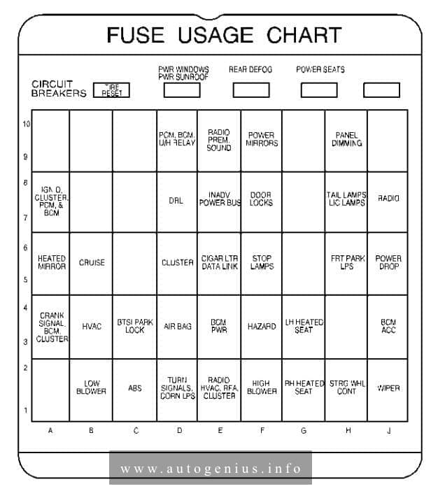
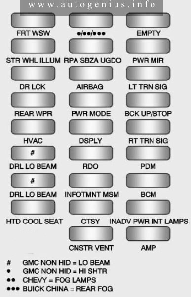
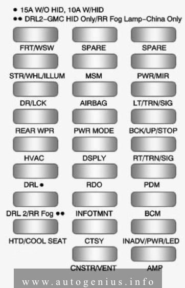
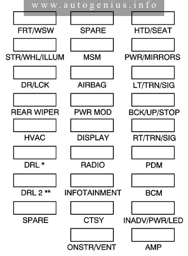
Assignment of the fuses in the passenger compartment
| Circuit Breakers | Usage |
| TIRE RESET | Tire Inflation Monitor Reset Button |
| PWR WINDOWS, PWR SUNROOF | Power Windows, Power Sunroof |
| REAR DEFOG | Rear Window Defogger |
| POWER SEATS | Power Seat |
| Blank | Not Used |
| Fuses | Usage |
| Blank | Not Used |
| Blank | Not Used |
| Blank | Not Used |
| PCM, BCM, U/H RELAY | Ignition Signal: Hot in Run and Start, Powertrain Control Module, Body Control Module, Underhood Relay |
| RADIO PREM. SOUND | Remote Radio Premium Sound |
| POWER MIRRORS | Power Mirrors |
| Blank | Not Used |
| PANEL DIMMING | Panel Dimming |
| Blank | Not Used |
| IGN 0, CLUSTER, PCM, BCM | Ignition Signal: Hot in Run, Unlock and Start; Cluster, Powertrain Control Module, Body Control Module |
| Blank | Not Used |
| Blank | Not Used |
| DRL | Daytime Running Lamps Module |
| INADV POWER BUS | Interior Lamps, Retained Accessory Power |
| DOOR LOCKS | Door Locks |
| Blank | Not Used |
| TAIL LAMPS, LIC LAMPS | Taillamps, License Lamps |
| RADIO | Radio |
| HEATED MIRROR | Heated Mirrors |
| CRUISE | Cruise Control |
| Blank | Not Used |
| CLUSTER | Instrument Panel Cluster |
| CIGAR LTR, DATA LINK | Cigarette Lighter, Auxiliary Power Connection (Power Drop), Data Link |
| STOP LAMPS | Stoplamps |
| Blank | Not Used |
| FRT PARK LPS | Parking Lamps |
| POWER DROP | Auxiliary Power Connection (Power Drop): Hot in ACC and Run |
| CRANK SIGNAL, BCM, CLUSTER | Crank Signal, Body Control Module, Cluster, Powertrain Control Module |
| HVAC | Ignition Signal, HVAC Control Head |
| BTSI PARK LOCK | Shifter Lock Solenoid |
| AIR BAG | Air Bag |
| BCM PWR | Body Control Module |
| HAZARD | Hazard Warning Flashers |
| LH HEATED SEAT | Driver’s Heated Seat |
| Blank | Not Used |
| BCM ACCY | Ignition Signal: Hot in ACCESSORY and RUN, Body Control Module |
| Blank | Not Used |
| LOW BLOWER | Low Blower |
| ABS | Anti-Lock Brakes |
| TURN SIGNALS, CORN LPS | Turn Signals, Cornering Lamps |
| RADIO, HVAC, RFA, CLUSTER | Radio, HVAC Head, Remote Keyless Entry, Cluster |
| HIGH BLOWER | High Blower |
| RH HEATED SEAT | Passenger’s Heated Seat |
| STRG WHL CONT | Audio Steering Wheel Controls |
| WIPER | Wipers |
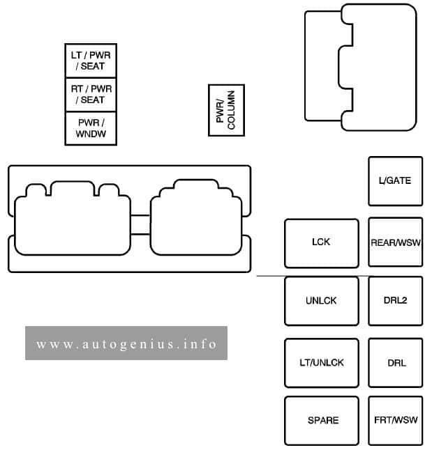
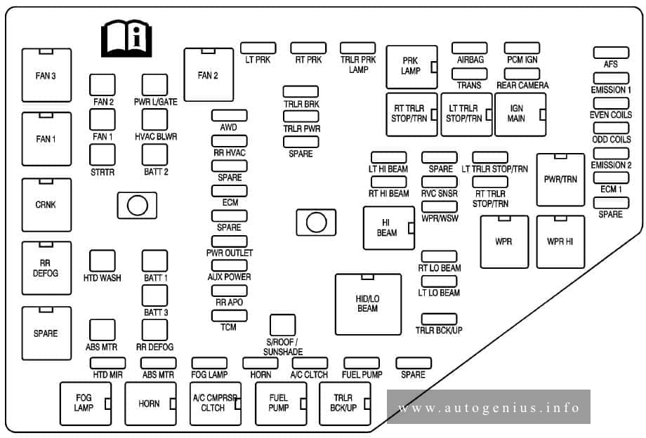
Engine compartment
Fuse box location
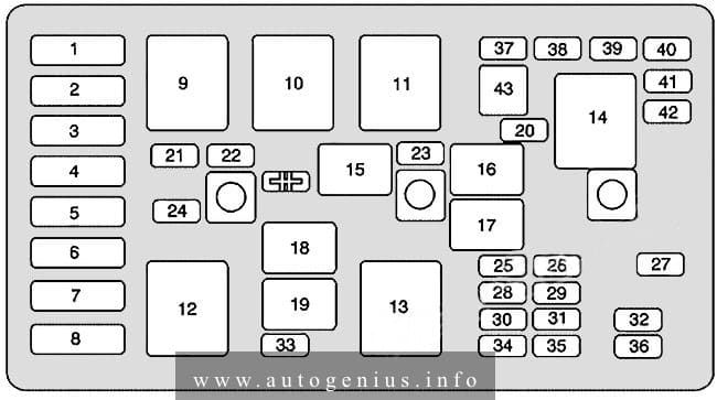
Some fuses and relays are located in the underhood fuse block on the passenger’s side of the vehicle in the engine compartment.
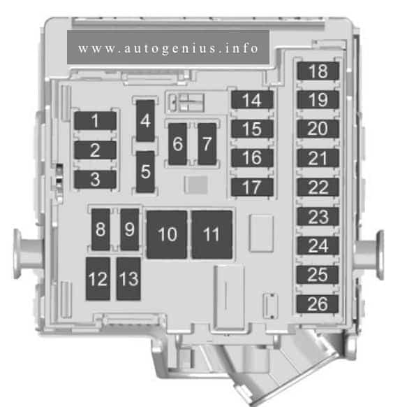
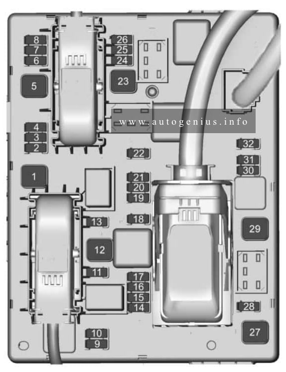
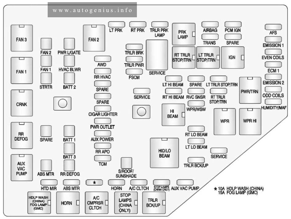
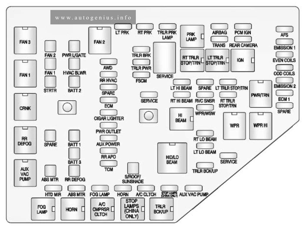
Fuse box diagram

Assignment of the fuses in the engine compartment
| Maxi Fuses | Usage |
| 1 | ABS |
| 2 | Starter Solenoid |
| 3 | Power Seats, Rear Defog |
| 4 | High Blower, Hazard Flasher, Stoplamps, Power Mirror, Door Locks |
| 5 | Ignition Switch, BTSI, Stoplamps, ABS, Turn Signals, Cluster, Air Bag, DRL Module |
| 6 | Cooling Fan |
| 7 | Interior Lamps, Retained Accessory Power, Keyless Entry, Data Link, HVAC Head, Cluster, Radio, AUX Power (Power Drop), Cigarette Lighter |
| 8 | Ignition Switch, Wipers, Radio, Steering Wheel Controls, Body Control Module, AUX Power (Power Drop), Power Windows, Sunroof, HVAC Controls, DRL, Rear Defog Relay |
| Mini Relays | Usage |
| 9 | Cooling Fan 2 |
| 10 | Cooling Fan 3 |
| 11 | Starter Solenoid |
| 12 | Cooling Fan 1 |
| 13 | Ignition Main |
| 14 | Air Pump (Optional) |
| Micro Relays | Usage |
| 15 | A/C Clutch |
| 16 | Horn |
| 17 | Not Used |
| 18 | Not Used |
| 19 | Fuel Pump |
| Mini Fuses | Usage |
| 20 | Air Pump (Optional) |
| 21 | Generator |
| 22 | ECM |
| 23 | A/C Compressor Clutch |
| 24 | Cooling Fan |
| 25 | Electronic Ignition |
| 26 | Transaxle |
| Mini Relay | Usage |
| 27 | Horn |
| 28 | Fuel Injector |
| 29 | Oxygen Sensor |
| 30 | Engine Emissions |
| 31 | Not Used |
| 32 | Headlamp (Right) |
| 33 | Rear Compartment Release |
| 34 | Parking Lamps |
| 35 | Fuel Pump |
| 36 | Headlamp (Left) |
| 37 | Spare |
| 38 | Spare |
| 39 | Spare |
| 40 | Spare |
| 41 | Spare |
| 42 | Spare |
| 43 | Fuse Puller |
| SYMBOL | Air Conditioner Compressor Clutch Diode |
WARNING: Terminal and harness assignments for individual connectors will vary depending on vehicle equipment level, model, and market.