Holden Acadia (2018 – 2020) – fuse and relay box diagram
Year of production: 2018, 2019, 2020
The Holden Acadia (AC), a mid-size crossover SUV, was manufactured between 2018 and 2020. This article provides fuse box diagrams for the 2018, 2019, and 2020 Holden Acadia models, details the locations of the fuse panels within the vehicle, and explains the function and layout of each fuse and relay.
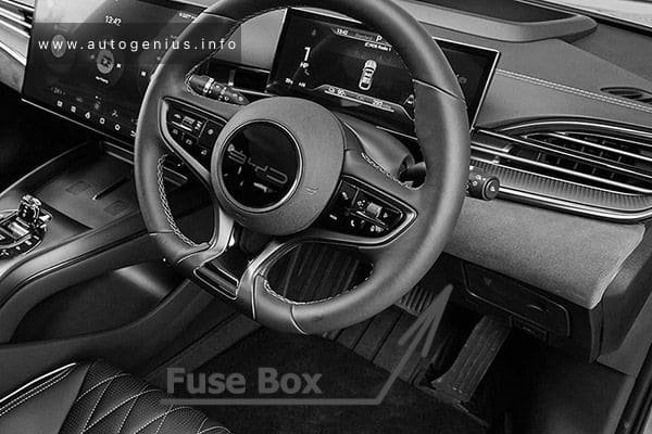
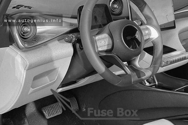
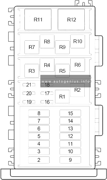
Passenger Compartment Fuse Box
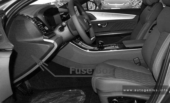
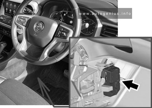
Fuse Box Location
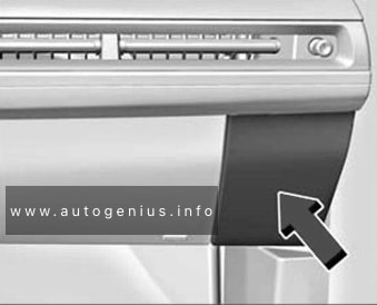
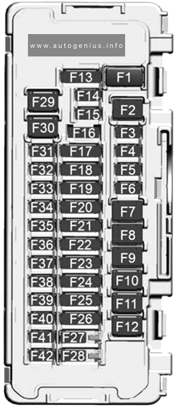
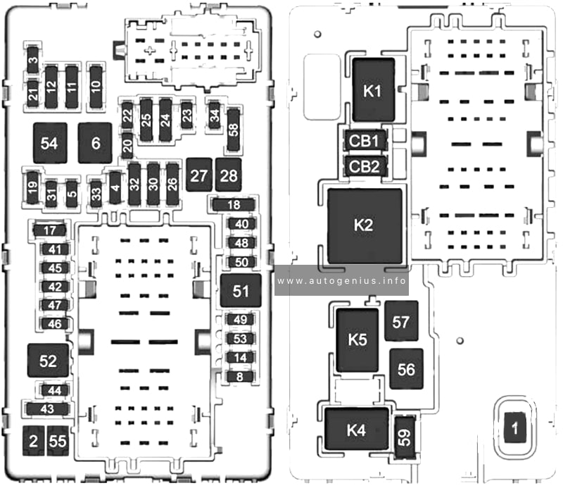
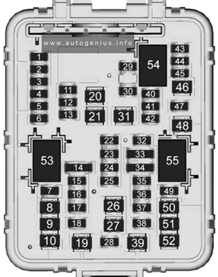
The instrument panel fuse block is inside the centre console on the right-hand side of the vehicle.
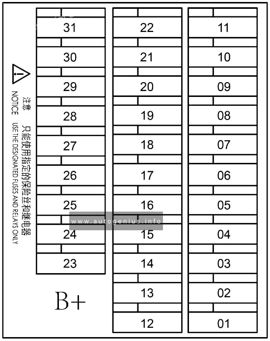
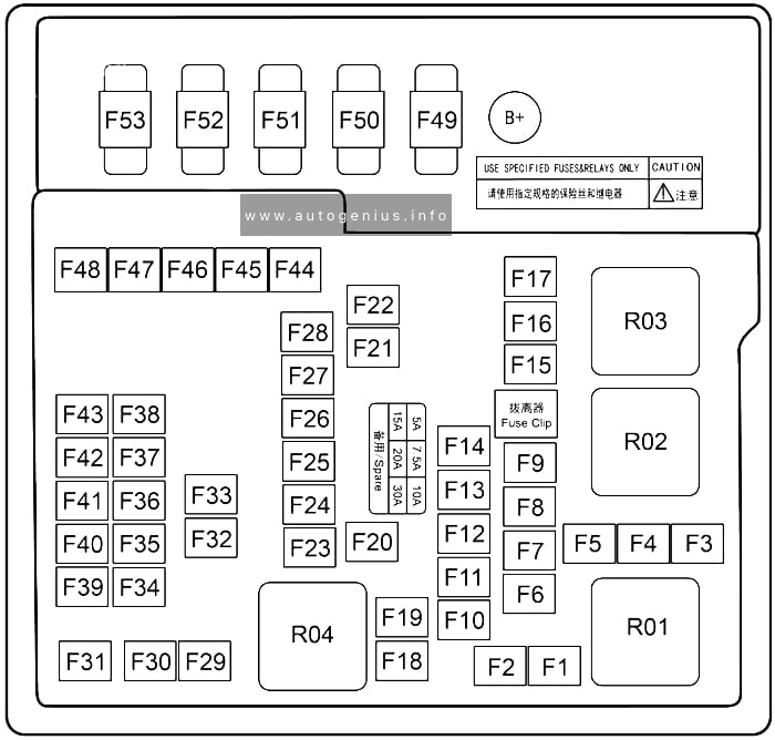
Fuse Box Diagram
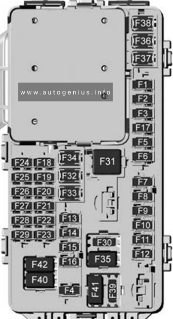
Assignment of the fuses in passenger compartment
| № | Usage |
|---|---|
| F1 | Body control module 6 |
| F2 | Diagnostic link / Central gateway module |
| F3 | Electric steering column lock |
| F4 | – |
| F5 | – |
| F6 | Heating, ventilation, and air conditioning |
| F7 | Body control module 3 |
| F8 | – |
| F9 | Right front heated seat |
| F10 | Airbag / Seat belt |
| F11 | – |
| F12 | Amplifier / Noise control module |
| F13 | Body control module 7 |
| F14 | Left front heated seat |
| F15 | – |
| F16 | Sunroof |
| F17 | – |
| F18 | Instrument cluster |
| F19 | Body control module 1 |
| F20 | Rear seat entertainment |
| F21 | Body control module 4 |
| F22 | Infotainment USB data / Aux jack |
| F23 | Body control module 2 |
| F24 | USB charger / Wireless charging |
| F25 | Ultrasonic park aid |
| F26 | CIM |
| F27 | – |
| F28 | Heating, ventilation, and air conditioning display |
| F29 | Radio |
| F30 | Steering wheel adjustment controls |
| F31 | 2018-2019: Front blower 2020: Electronic brake control module electric brake booster |
| F32 | DC AC inverter |
| F33 | Driver power seat |
| F34 | Passenger power seat |
| F35 | Battery IEC 1 feed |
| F36 | Electric power steering |
| F37 | Rear seat entertainment / USB charge / Wireless charging module / Auxiliary power outlet |
| F38 | Body control module 8 |
| F39 | – |
| Circuit Breakers | |
| F40 | – |
| F41 | – |
| F42 | Auxiliary power outlet / Lighter |
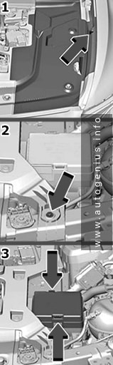
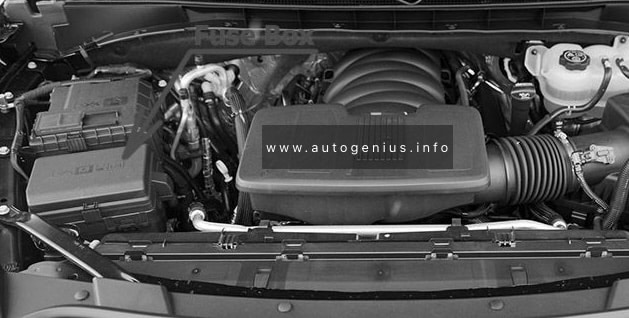
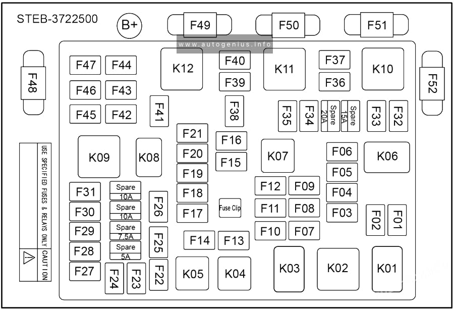
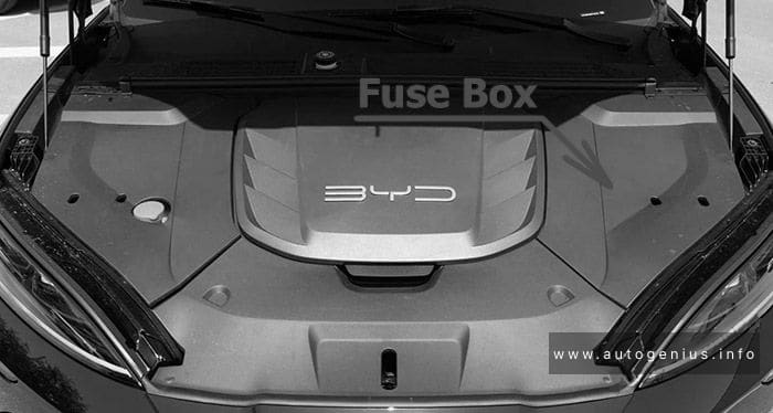
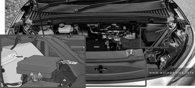
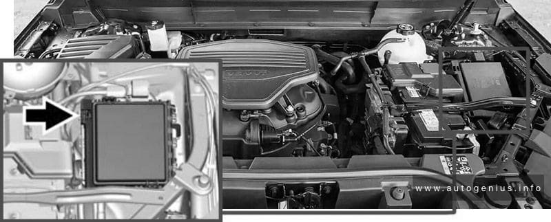
Engine Compartment Fuse Box
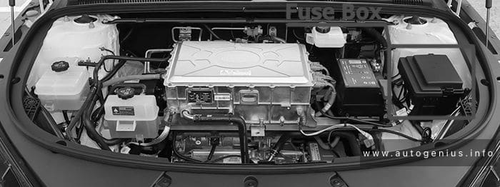
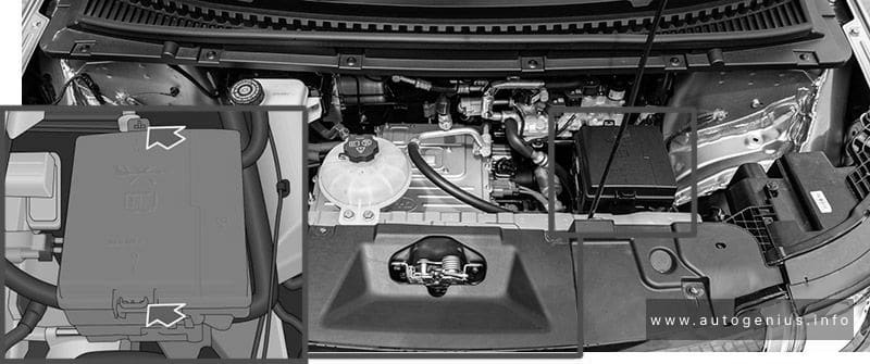
Fuse Box Location
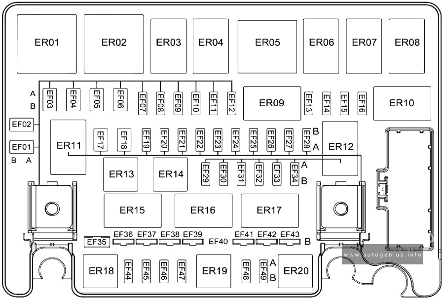
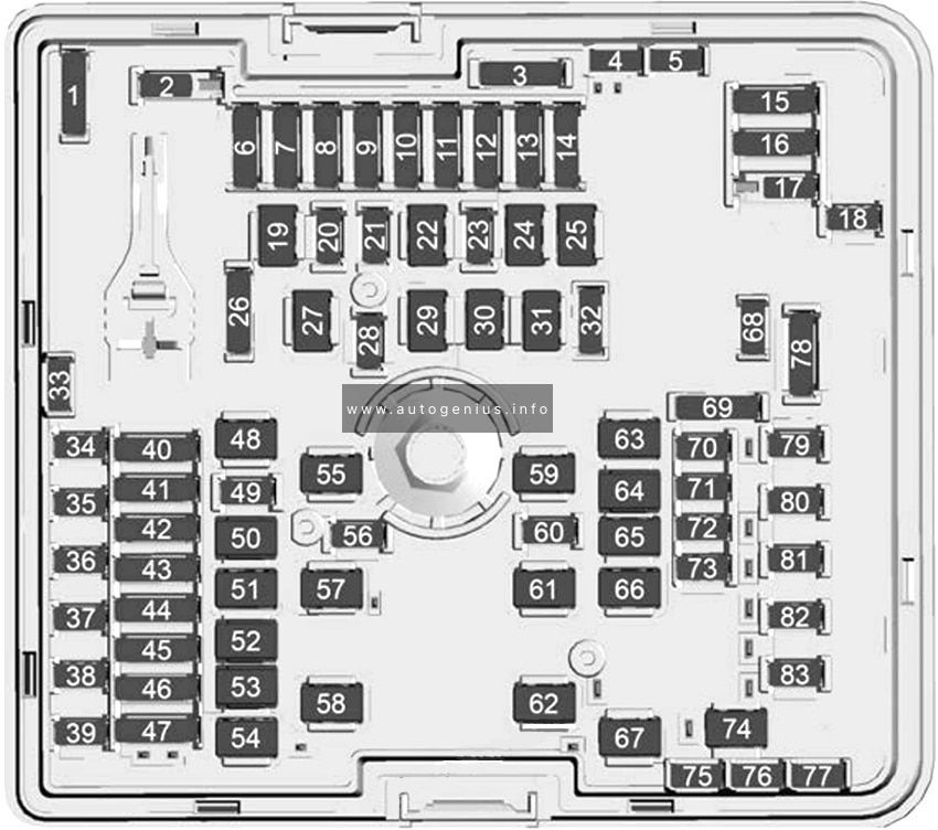
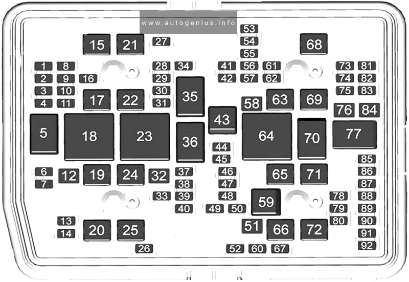
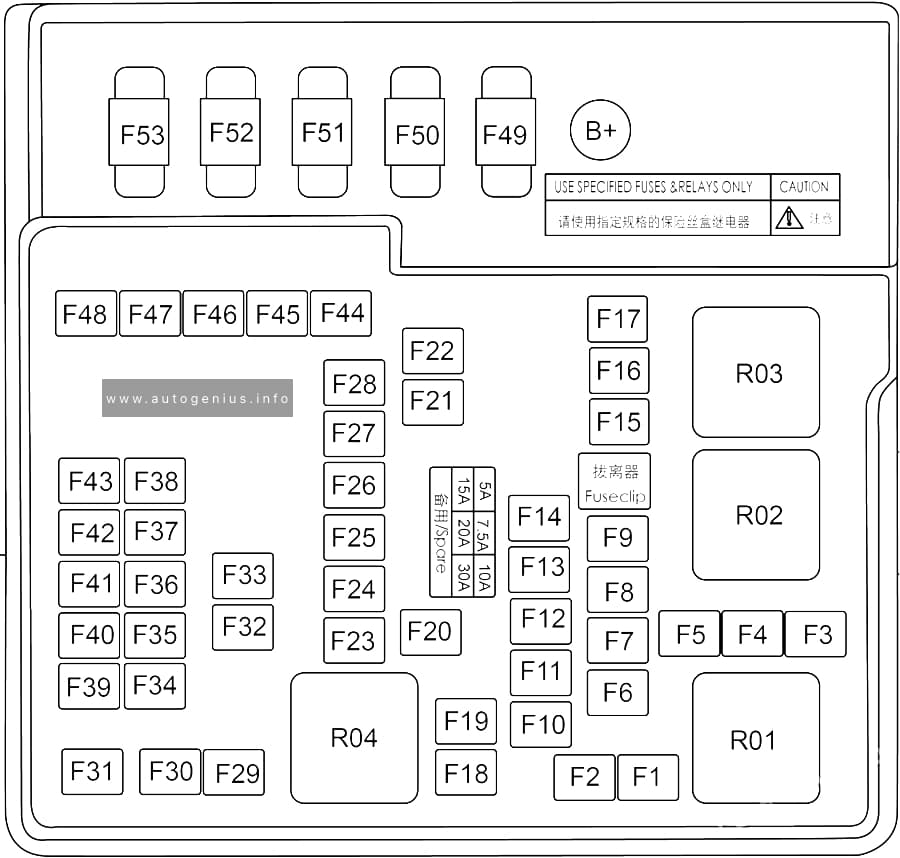
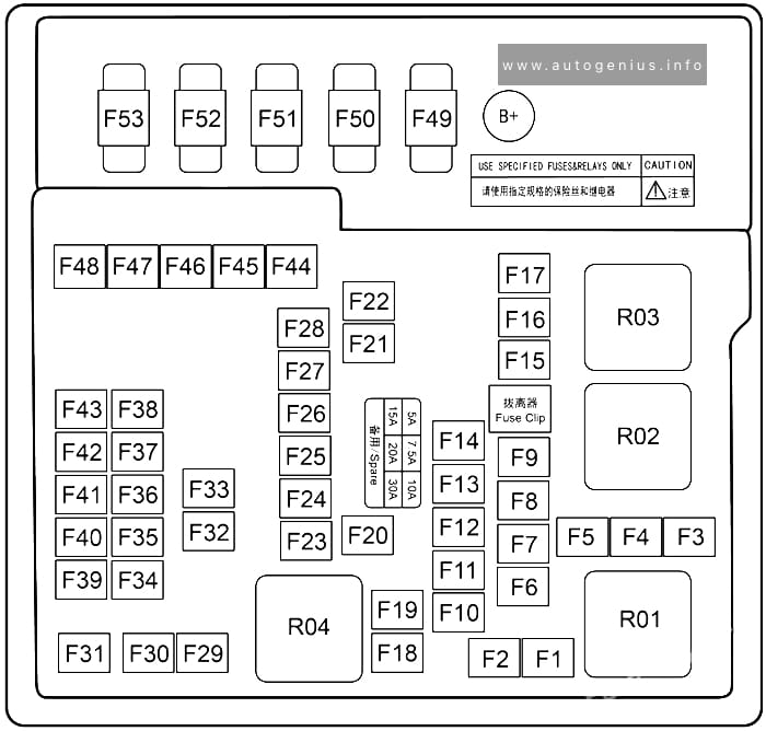
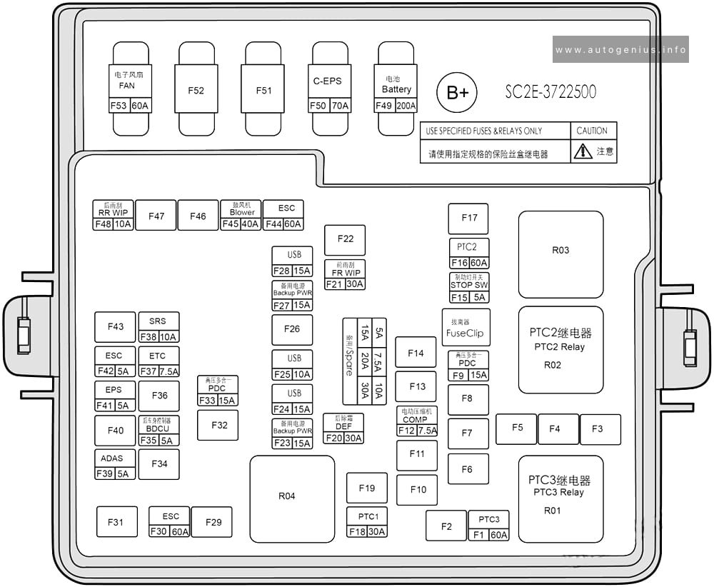
Fuse Box Diagram
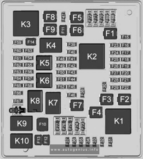
Assignment of the fuses in the engine compartment
| № | Usage |
|---|---|
| F1 | Antilock brake system |
| F2 | Starter 1 |
| F3 | DC/DC transformer 1 |
| F4 | – |
| F5 | DC/DC transformer 2 |
| F6 | – |
| F7 | 2018-2019: Electronic brake control module eboost 2020: Front blower |
| F8 | Starter 3 |
| F9 | – |
| F10 | 2020: Brake lamp trailer |
| F11 | – |
| F12 | Front wiper |
| F13 | 2020: Starter 2 |
| F14 | – |
| F15 | Rear wiper |
| F16 | – |
| F17 | – |
| F18 | – |
| F19 | – |
| F20 | – |
| F21 | – |
| F22 | Electronic brake control module |
| F23 | Parking / Trailer lamps |
| F24 | Right trailer stop lamp / lndicator lamp |
| F25 | Steering column lock |
| F26 | – |
| F27 | Left trailer stop lamp / Indicator lamp |
| F28 | – |
| F29 | – |
| F30 | Washer pump |
| F31 | Spare / Headlamp low-beam right |
| F32 | Headlamp low-beam left |
| F33 | Headlamp hi-beam shutter / Fog lamps |
| F34 | Horn |
| F35 | – |
| F36 | Headlamp low-beam right / Headlamp high-beam left |
| F37 | Spare / Headlamp high-beam right |
| F38 | Automatic headlamp levelling motor |
| F39 | Transmission control module |
| F40 | Left rear bus electrical centre / Ignition |
| F41 | Instrument cluster |
| F42 | Heating, ventilation, and air conditioning / Central gateway module run/crank |
| F43 | Reflective light alert display |
| F44 | Electronic brake control module eboost run/crank |
| F45 | – |
| F46 | – |
| F47 | – |
| F48 | – |
| F49 | Interior rear view mirror / Trailer |
| F50 | Fuel system control module / Fuel tank zone module run / crank |
| F51 | Heated steering wheel |
| F52 | Air conditioning clutch |
| F53 | – |
| F54 | Coolant pump |
| F55 | – |
| F56 | |
| F57 | Engine control module / lgnition |
| F58 | Transmission control module / lgnition |
| F59 | Engine control module battery |
| F60 | – |
| F61 | O2 sensor 1 / Aero shutter / Mass air flow sensor |
| F62 | Engine control module – odd |
| F63 | O2 sensor 2 |
| F64 | Engine control module – even |
| F65 | Engine control module powertrain 1 |
| F66 | Engine control module powertrain 2 |
| F67 | Engine control module powertrain 3 |
| F68 | – |
| F69 | – |
| F70 | – |
| F71 | – |
| F72 | – |
| F73 | – |
| F74 | – |
| F75 | – |
| F76 | – |
| F77 | – |
| Relays | |
| K1 | Starter 1 |
| K2 | Run/Crank |
| K3 | Starter 3 |
| K4 | – |
| K5 | – |
| K6 | Coolant pump |
| K7 | Engine control module |
| K8 | Air conditioning |
| K9 | 2020: Brake trailer lamp |
| K10 | 2020: Starter 2 |
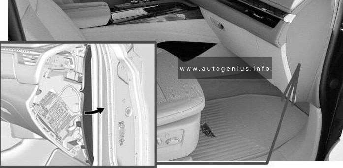
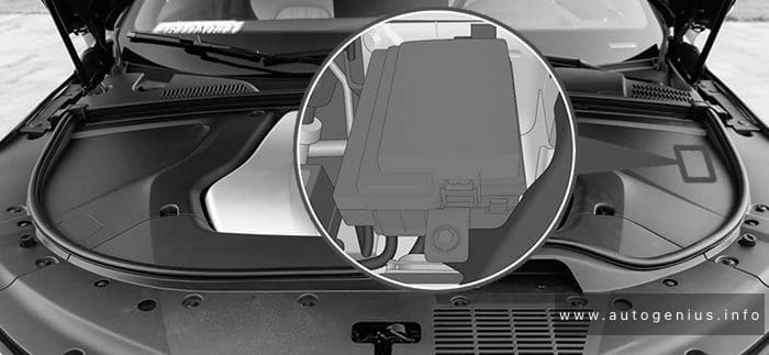
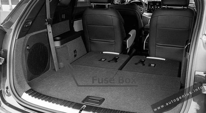
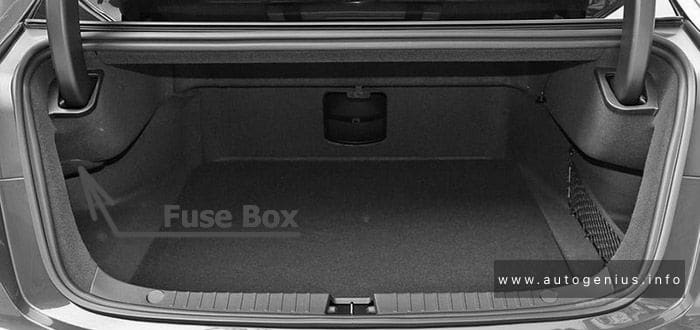
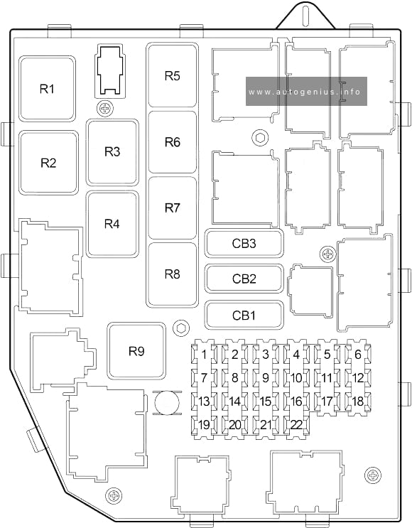
Rear Compartment Fuse Box
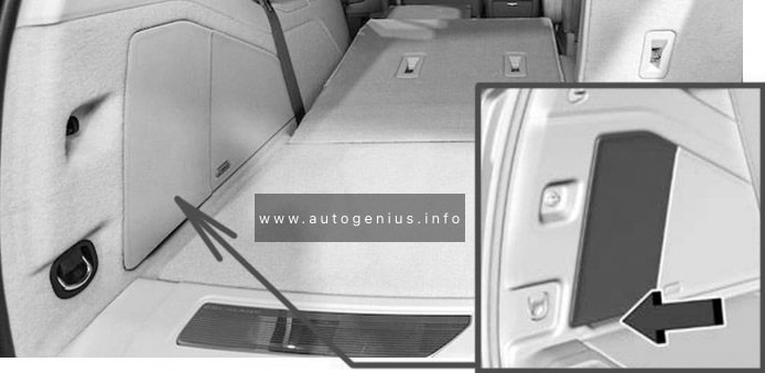
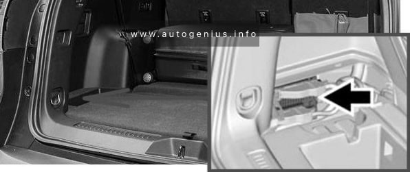
Fuse Box Location
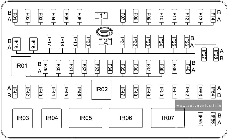
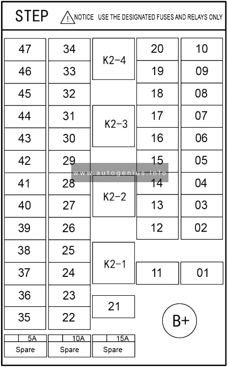
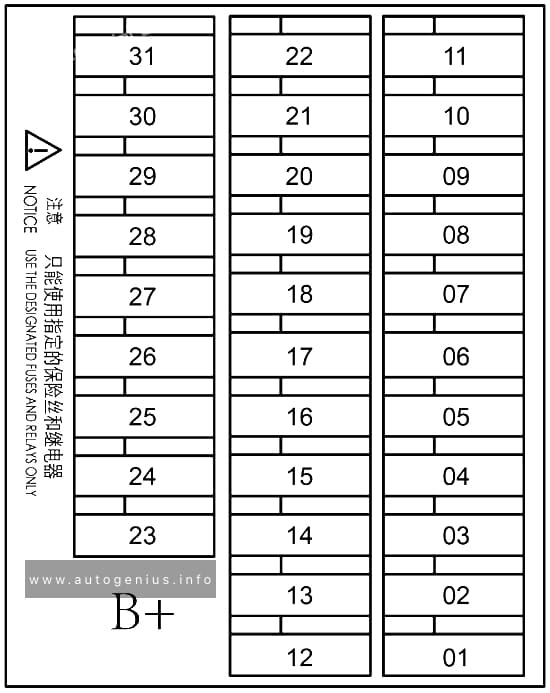
The rear fuse panel is located below the left-hand side trim panel in the rear compartment.
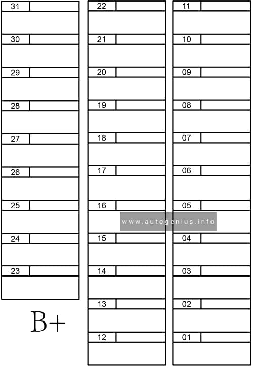
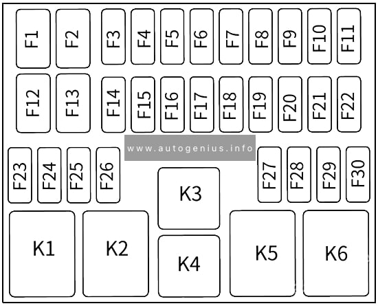
Fuse Box Diagram
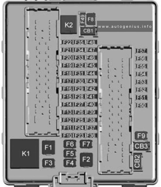
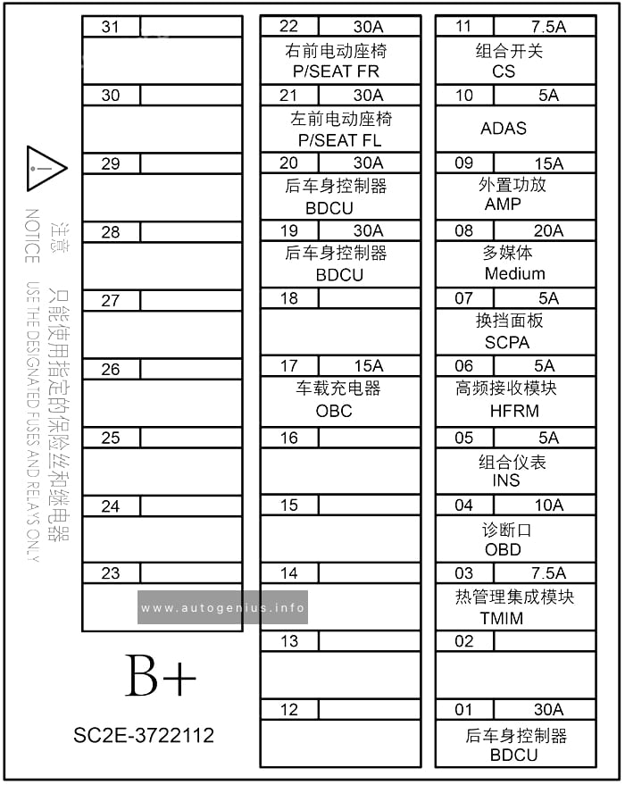
Assignment of the fuses in the rear compartment
| № | Usage |
|---|---|
| F1 | – |
| F2 | Trailer battery |
| F3 | – |
| F4 | Rear blower |
| F5 | Rear drive control 1 |
| F6 | – |
| F7 | Right window |
| F8 | Rear demister |
| F9 | Left window |
| F10 | – |
| F11 | Trailer reverse |
| F12 | – |
| F13 | – |
| F14 | – |
| F15 | – |
| F16 | – |
| F17 | – |
| F18 | – |
| F19 | – |
| F20 | Glove box door / Trailer brake lamp |
| F21 | – |
| F22 | – |
| F23 | – |
| F24 | – |
| F25 | – |
| F26 | Trailer brake |
| F27 | Driver ventilated seat / Lumbar |
| F28 | Passive entry / Passive start |
| F29 | – |
| F30 | Canister vent |
| F31 | – |
| F32 | Heated mirror |
| F33 | – |
| F34 | Liftgate module |
| F35 | Fuel system control module / Fuel tank zone module |
| F36 | Passenger ventilated seat / Lumbar |
| F37 | – |
| F38 | Window module |
| F39 | Rear closure |
| F40 | Memory seat module |
| F41 | Automatic occupancy sensor |
| F42 | – |
| F43 | – |
| F44 | – |
| F45 | Liftgate motor |
| F46 | Rear heated seats |
| F47 | – |
| F48 | – |
| F49 | – |
| F50 | – |
| F51 | – |
| F52 | Rear drive control 2 / Active dampening system module |
| F53 | Video |
| F54 | External object calculating / Side blind zone alert |
| F55 | – |
| F56 | Universal garage door opener / Rain sensor |
| F57 | Theft deterrent |
| Circuit Breakers | |
| CB1 | – |
| CB2 | – |
| CB3 | Rear auxiliary power outlet |
| Relays | |
| K1 | – |
| K2 | – |
WARNING: Terminal and harness assignments for individual connectors will vary depending on vehicle equipment level, model, and market.