The pre-facelift MG ZS, a subcompact crossover, was produced from 2017 to 2020. This article includes fuse box diagrams for the 2017 through 2020 models, provides details on the locations of the fuse panels inside the vehicle, and explains the function of each fuse (fuse layout).
Fuse Box Location
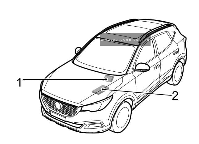
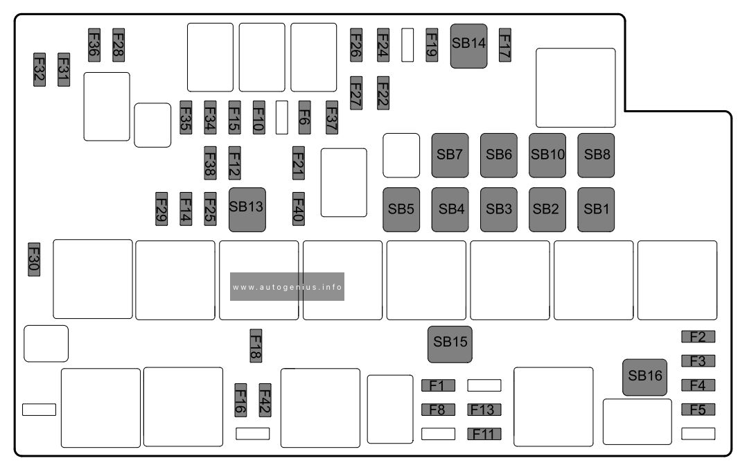
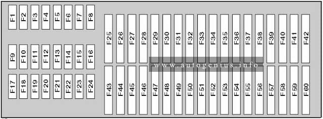
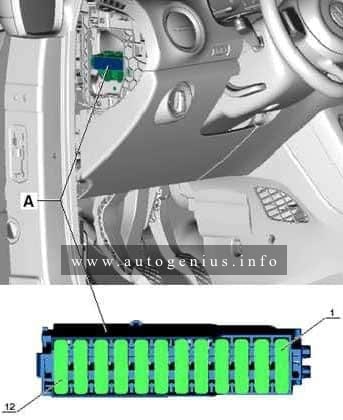
MG ZS (2017 – 2020) – fuse and relay box location
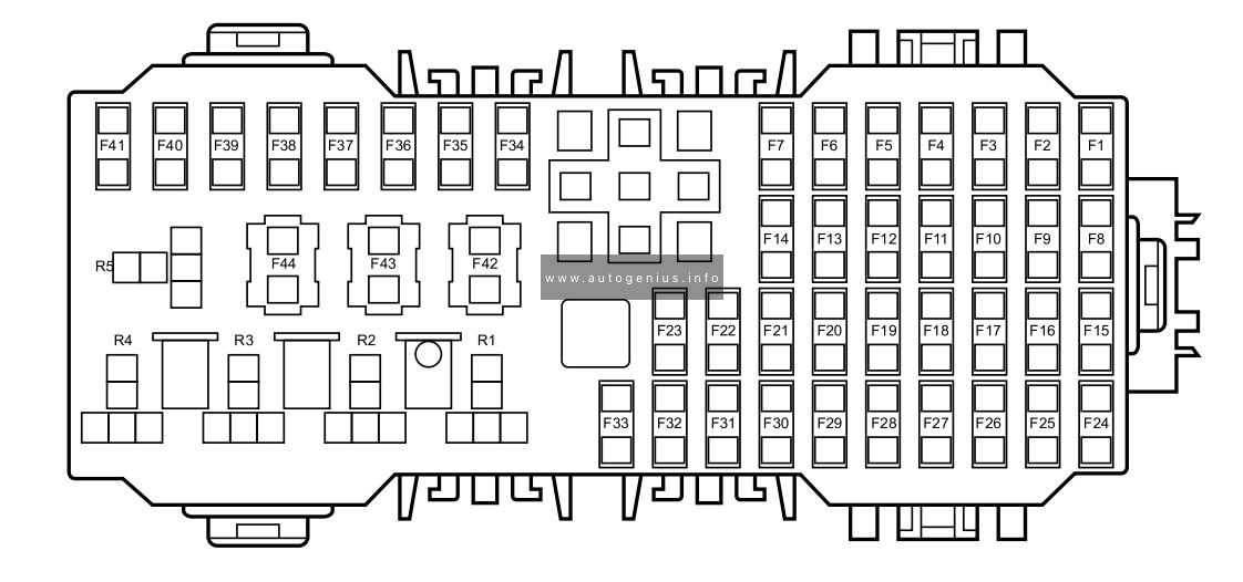
Passenger Compartment Fuse Box(below the glove box at the front passenger side
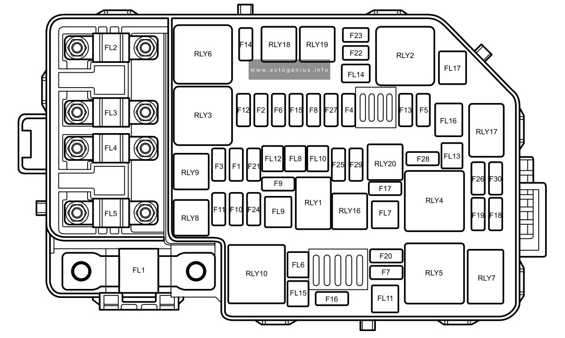
Engine Compartment Fuse Box(at the left side of the Engine Compartment
This article focuses on the facelifted first-generation MG MG6, produced from 2014 to 2016. It includes fuse box diagrams for the 2014, 2015, and 2016 models, provides information on the locations of the fuse panels inside the vehicle, and outlines the function of each fuse (fuse layout).
The MG GS, a compact crossover, was manufactured from 2015 to 2019. This article includes fuse box diagrams for the 2015 through 2019 models, provides information on the locations of the fuse panels inside the vehicle, and details the function of each fuse (fuse layout).
Lincoln Navigator (UN173; 1998) – fuse and relay box diagram
Year of production: 1998
This article covers the first-generation Lincoln Navigator, manufactured between 1998 and 2002. It includes fuse box diagrams for the 1998 models, provides details on the locations of the fuse panels within the vehicle, and explains the function and layout of each fuse and relay.
Engine compartment fuse panel
Fuse box location
The power distribution box is located in the engine compartment (on the driver’s side).
Fuse box diagram
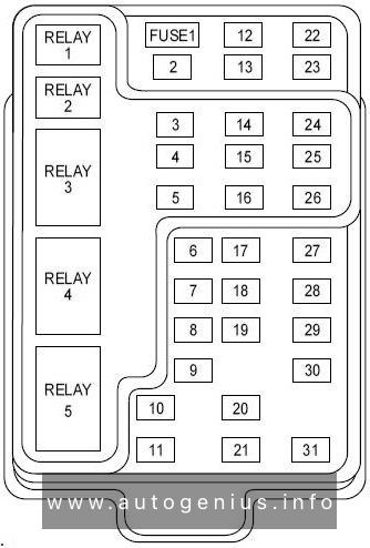
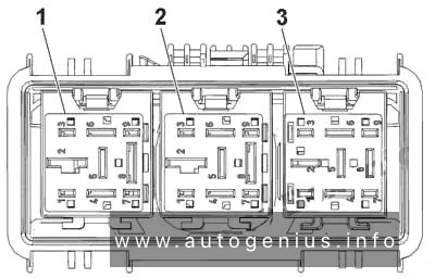
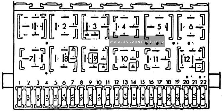
Lincoln Navigator (UN173; 1998) – fuse and relay box diagram – engine compartment
Assignment of the fuses and relays in the engine compartment (1998)
No.
A
Circuit Protected
1
15A
Flasher Relay
2
5A
Instrument Cluster, Overhead Trip Computer (OTC) Module, Redundant Steering Control Module, Electronic Automatic Temperature Control (EATC) Module, Clock
3
25A
Cigar Lighter
4
5A
Park Lamp Relay, Headlamp Relay, Autolamp Module, Remote Anti-theft Personality (RAP) Module, Power Mirror Switch, Memory Seat and Mirror Module, Driver Power Seat Control Switch, Memory Seat Switch
5
15A
Digital Transmission Range (DTR) Sensor, Daytime Running Lamps (DRL) Module, Speed Control Servo/Amplifier Assembly, EATC Clutch Relay
Heated Backlite Switch, Left Power/Heated Signal Mirror, Right Power/Heated Signal Mirror
18
5A
Main Light Switch, Generic Electronic Module (GEM), Instrument Illumination, (Power supplied through Main Light Switch), Park Lamp Relay, Trailer Electronic Brake Control, Trailer Tow Running Lamp Relay, Left Side Marker Lamps, Right Side Marker Lamps, Left Front Park/Turn Lamp, Right Front Park/Turn Lamp, Left Stop/Park/Tum Lamp, Right Stop/Park/Tum Lamp, Left License Lamp, Right License Lamp
19
10A
Instrument Cluster, Air Bag Diagnostic Monitor
20
5A
4 Wheel Air Suspension 4WAS Generic Electronic Module (GEM), Memory Seat and Mirror Module
21
15A
Digital Transmission Range (DTR) Sensor, Junction Box Fuse/Relay Panel (Fuse 20)
22
10A
Air Bag Diagnostic Monitor, Ignition Swatch
23
10A
Trailer Tow Battery Charge Relay, 4X4 Center Axle Disconnect Solenoid, 4X2 Center Axle Disconnect Solenoid, Electronic Day/Night Mirror, Rear Integrated Control Panel, Auxiliary A/C Mode Actuator, Auxiliary A/C Control Module, Auxiliary A/C Blend Actuator Flasher Relay
24
10A
Electronic Automatic Temperature Control (EATC) Module, Console Blower Relay, Auxiliary A/C Relay
25
5A
4 Wheel Anti-Lock Brake System (4WABS) Module 4WABS Relay
26
10A
Daytime Running Lamps (DRL) Module, Right Headlamp (Powder supplied through Multi-Function Swatch)
27
5A
Main Light Swatch, Fog Lamp Relay
28
10A
Left Headlamp
29
5A
Autolamp Module, Instrument Cluster, Transmission Control Swatch (TCS)
30
30A
Radio Noise Capacitor, PCM Power Diode, Coil on Plugs, PCM Powder Relay, SecuriLock
31
–
Not Used
31
10
Rear Integrated Control Panel (Audio), CD Player, Cell Phone
Engine Compartment Fuse Box
Power fuse box
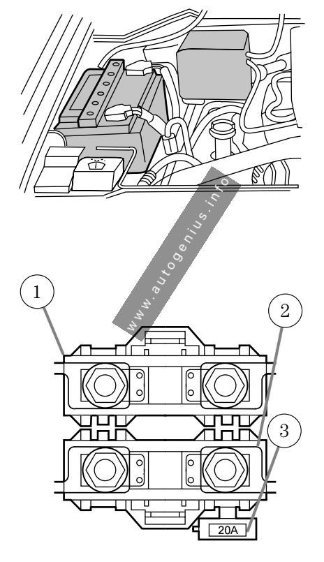
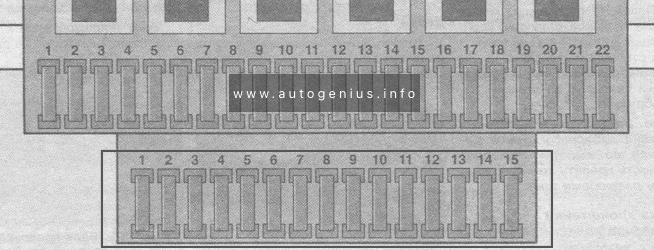
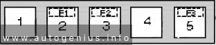
Lincoln Navigator (UN173; 1998) – fuse and relay box diagram – passenger compartment (power fuse box)
Assignment of the fuses and relays in the power fuse box (1998)
Location
Amperage
Description
1
175
Power Network Box Megafuse
2
175
Alternator Megafuse
3
20
Alternator Field Minifuse
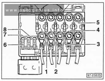
Additional fuse panel
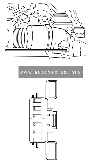
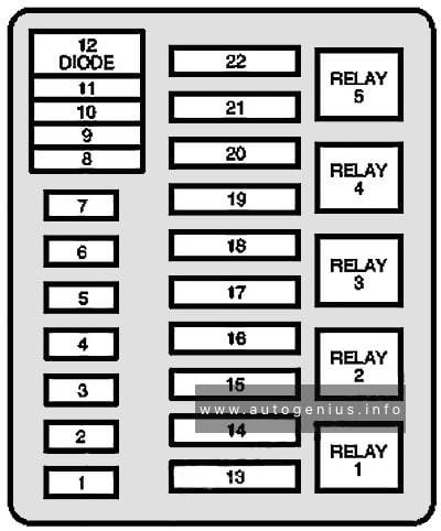
Lincoln Navigator (UN173; 1998) – fuse and relay box diagram – passenger compartment (engine mini fuse box)
Assignment of the fuses and relays in the additional fuse panel (1998)
Slot number
Ampere rating [A]
Circuit protected
1
5
Powertrain Control Module (PCM)
2
20
Trailer Tow Stop/Turn Lamps
3
10
Audio Rear Integrated Control Panel (RICP), Compact Disc Changer, Radio
4
10
Running Board Lamps
5
20
Amplifier, Subwoofer Amplifier
6
—
Not used
Passenger compartment box
Fuse box location
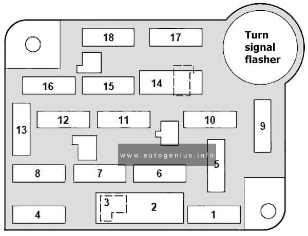
The fuse panel is located below and to the left of the steering wheel behind the cover.
Fuse box diagram
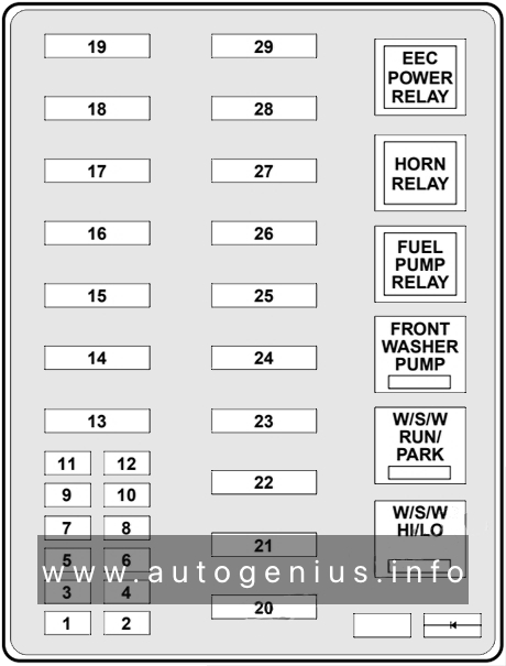
Lincoln Navigator (UN173; 1998) – fuse and relay box diagram – passenger compartment
Assignment of the fuses and relays in the passenger compartment (1998)
№
Amp Rating
Description
1
20A
Trailer Tow Running Lamp Relay, Trailer Tow Backup Lamp Relay
2
10A
Air Bag Diagnostic monitor
3
30A
All Unlock Relay, All Lock Relay, Driver’s Unlock Relay
4
15A
Air Suspension Sendee Switch
5
20A
Horn Relay
6
30A
Radio, Premium Sound Amplifier, CD Changer, Rear Integrated Control Panel, Sub-Woofer power
7
15A
Main Light Switch, Park Lamp Relay
8
30A
Main Light Switch, Headlamp Relay, Multi-Function Switch
9
15A
Daytime running lamps (DRL) Module, Fog Lamp Relay
10
25A
I/P Auxiliary Power Socket
11
25A
Console Auxiliary Power Socket
12
10A
Rear Wiper Up Motor Relay, Rear Wiper Down Motor Relay
13
30A
Auxiliary A/C Relay
14
60A
4 Wheel Anti-Lock Brake System (4WABS) Module
15
50A
Air Suspension Solid State Compressor Relay
16
40A
Trailer tow battery Charge Relay, Mini Fuse Block (fuse 2), Trailer Tow Right Turn Relay, Trailer tow Left Turn Relay
17
30A
Transfer Case Shift Relay, Torque on Demand Relay
18
30A
Memory Seat Module
19
20A
Fuel Pump Relay
20
50A
Ignition Switch
21
50A
Ignition Switch
22
50A
Junction Box Fuse/Relay Panel Battery Feed
23
40A
I/P Blower Relay
24
30A
PCM Power Relay, Mini Fuse Block (fuse 1), Powertrain Control Module
25
30A (CB)
Junction Box Fuse/Relay Panel, ACC Delay Relay
26
30A
Passenger Power Seat Control Switch
27
40A
Junction Box Fuse/Relay Panel, Heated Grid Relay
28
30A
Trailer Electronic Brake Control
29
30A
RPO Relay Block, Vent Window/Moonroof Relay
WARNING: Terminal and harness assignments for individual connectors will vary depending on vehicle equipment level, model, and market.
Chevrolet Cruze (J300; 2008 – 2016) – fuse and relay box diagram
Year of production: 2008, 2009, 2010, 2011, 2012, 2013, 2014, 2015, 2016
This article focuses on the first-generation Chevrolet Cruze (J300), manufactured between 2008 and 2016. It includes fuse box diagrams for the 2008 to 2016 models, provides details on the locations of the fuse panels inside the vehicle, and explains the function and layout of each fuse and relay.
Engine compartment fuse box
Fuse box diagram
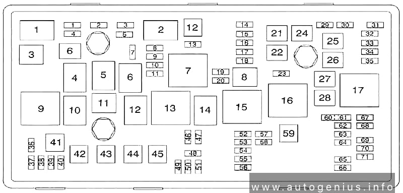
Chevrolet Cruze (J300; 2008 – 2016) – fuse and relay box diagram – engine compartment
Assignment of the fuses and relay in the engine compartment
No.
A
Description
1
15
Transmission Control Module
2
15
Engine Control Module
3
N/A
Not Used
5
15
Transmission Control Module, Engine Control Module, Mass Air Flow/Intake Air Temperature Sensor, Output Speed Sensor
Ford F-150 (1992 – 1997) – fuse and relay box diagram
Year of production: 1992, 1993, 1993, 1994, 1995, 1996, 1997
This article focuses on the ninth-generation Ford F-Series, produced from 1992 to 1997. It provides fuse box diagrams for the 1992, 1993, 1994, 1995, 1996, and 1997 Ford F-150, F-250, and F-350 models, along with information on the locations of the fuse panels within the vehicle and the assignment of each fuse and relay (fuse layout).
Passenger Compartment Fuse Panel
Fuse box location
The fuse panel is located behind the cover to the left of the steering wheel. Remove the cover from the lower edge of the instrument panel by pulling on handle to disengage the fasteners.
Fuse box diagram
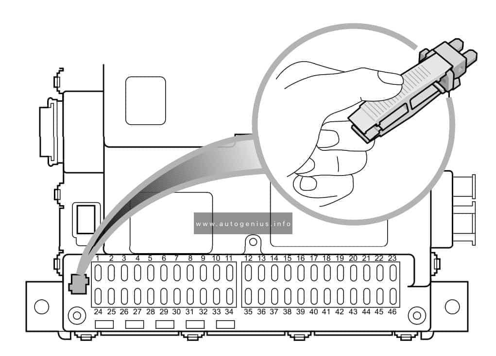
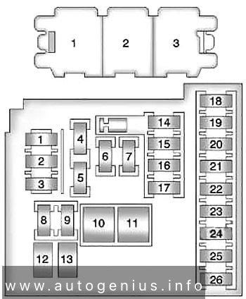
Ford F-150 – fuse and relay box diagram – passenger compartment
Volkswagen Tiguan (2008-2017) – fuse and relay box diagram
Year of production: 2008, 2009, 2010, 2011, 2012, 2013, 2014, 2015, 2016, 2017
This article covers the first-generation Volkswagen Tiguan, manufactured from 2007 to 2017. It includes fuse box diagrams for the 2008 to 2017 models, provides details on the location of the fuse panels inside the vehicle, and explains the function and layout of each fuse and relay.
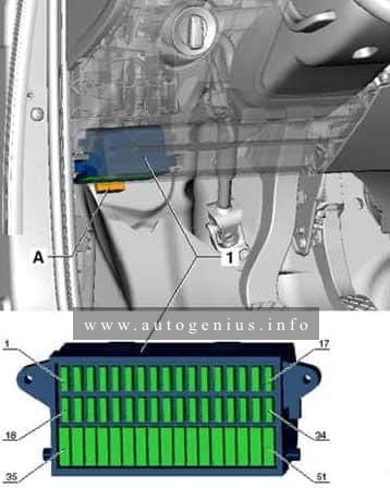
Passenger compartment
Fuse box location
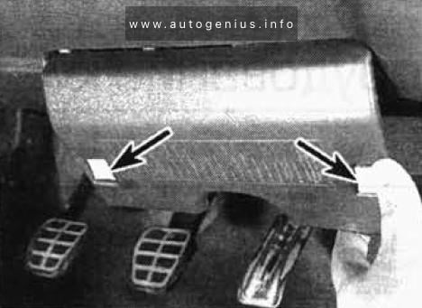
The fuse box is located behind the storage compartment below the steering wheel.
Assignment of the fuses in the instrument panel (fuse panel)
№
A
Circuits protected
1
–
2
–
3
–
4
–
5
–
6
–
7
–
8
–
9
5
Supplementary restraint system (SRS) control module
10
10
Four wheel drive control module
11
5
Parking aid control module, self-parking system control module
12
10
Gas discharge headlamp control module (LH)
13
5
ABS/ESP system, AC system, anti-dazzle interior mirror, heated windscreen washer jets, seat occupation control module, transmission control module (TCM), reversing lamps, engine management system
14
10
ABS control module, engine control module (ECM), heated seats, power steering control module, suspension control module, trailer control module, AC control module, instrumentation control module, CAN data bus gateway control module
15
10
Auxiliary heater, data link connector (DLC), parking brake control module, engine management, headlamp direction control module
16
10
Gas discharge headlamp control module (RH)
17
5
Instrument panel
18
10
Mobile telephone control module, multimedia control module
19
10
Steering column function control module 2
20
5
ABS control module, AC system, transmission control module (TCM)
21
15
Door function control module, left rear, door function control module, right rear, multifunction control module 2
22
5
Alarm system, multifunction control module 2
23
10
ABS/ESP system, AC system, data link connector (DLC), rear view camera control module, headlamp switch
24
10
Door function control module, driver, door function control module, passenger
25
20
Transmission control module (TCM)
26
–
27
–
28
40
AC control module, auxiliary heater
29
15
Rear screen wiper motor
30
–
31
20
Auxiliary power sockets, cigarette lighter
32
–
33
–
34
–
35
–
36
–
37
–
38
10
Steering column function control module 1
39
20
Headlamp washers
40
15
Trailer control module
41
15
Trailer control module
42
20
Trailer control module
43
25
Sunroof control module
44
25
Parking brake control module
45
25
Heater blower motor, heated rear window
46
30
Door function control module, driver, door function control module, passenger
47
30
Door function control module, driver, door function control module, right rear
Year of production: 19991, 1992, 1993, 1994, 1995, 1996, 1997
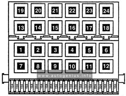
The 3rd generation Volkswagen Golf compact car was produced in 1991, 1992, 1993, 1994, 1995, 1996, 1997, 1998, 1999, 2000, 2001 and 2002 with gasoline and diesel engines. Delivered worldwide in various body styles: convertible, sedan, station wagon and hatchback. In this article you will find a designation of the fuse and relay boxes diagram of the 3rd generation Volkswagen Golf.
Passenger compartment
Fuse box location
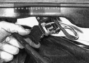
It is located at the bottom of the dashboard on the driver’s side, behind the protective cover. To remove it, press the buttons – latches.
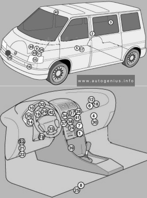
Year of production: 1990, 1991, 1992, 1993, 1994, 1995, 1996, 1997, 1998, 1999, 2000, 2001, 2002, 2003
Volkswagen Transporter T4 – represents the 4th generation of the legendary Transporter series. This model was produced in 1990, 1991, 1992, 1993, 1994, 1995, 1996, 1997, 1998, 1999, 2000, 2001, 2002 and 2003 with diesel and gasoline engines with different wheelbases: short and long, and with different roof height. Also on the T4, Volkswagen continued its lineup of luxury Caravelle, California and Multivan models. In this article, we will show the location of all electronic control sides and a detailed designation of the purpose of fuses and relays Volkswagen T4 with box diagrams in which they are located.
Air conditioning control unit 1 – with automatic temperature control – in the heater control panel, front
2
Air conditioning control unit 2 – with automatic temperature control – in the heater control panel, rear – central pillar
3
Evaporator Fan Control Unit (A / C) – With Rear A / C – Behind Right Rear Trim Panel
4
Air conditioning / heater fan motor control unit 1 – with automatic temperature control – front – fan unit
5
Air conditioning / heater blower motor control unit 2- with automatic temperature control – rear- bottom of the body, in the center
6
Aerial amplifier – behind the dash, passenger side
7
Alternator resistor – near additional relays – CV / AUF, with alternator 150A / automatic transmission / automatic temperature control – behind the central part of the dashboard
8
Additional battery – under the driver’s seat
9
Accumulator battery
10
Central locking signal control unit – behind the dashboard
11
Cruise control unit (with throttle motor) – cruise control is controlled by the ECM
12
Electronic cruise control module (without throttle motor) – behind dash, passenger side
13
Diagnostic connector (DLC) – instrument panel, driver’s side
14
Diagnostic unit – 05/99 (except for AAC / ABL / AET / AES / AJA) – in the instrument cluster
15
Cooling Fan Motor Relay – Behind Left Headlight
16
Cooling Fan Motor 1/2 Resistor – Behind Left Headlight
17
Coolant heater control unit (with additional coolant heater – D3W / B4W / D4W) – in the heater – underbody, in the center
18
Coolant heater control unit (with optional coolant heater – B7W / D7W) – behind the dash, passenger side
19
Engine oil pressure warning buzzer – in instrument cluster control unit
Windshield wiper / washer, heaters for windshield washer nozzles (05/01)
6
30
Air conditioning system, heater fan motor
7
10
Front right side / rear right side lamps
8
10
Lamps front left / rear left
9
20
Heated rear window, heated outside mirror
10
15
Fog lights
11
10
Left headlamp-high beam
12
10
RH headlamp-high beam
13
10
Sound signal
14
10
ABS system (with ESP), automatic transmission control system, additional equipment, central locking, cruise control system, power windows, power rear-view mirrors on the doors, reverse light (s)
Heater blower motor relay – automatic temperature control
5
(152)
Heater radiator coolant valve relay (rear heater)
6
(38)
Air intake changeover actuator relay (A / C / heater)
7
(53)
Alternator relay (AES, with 150A alternator)
8
(53)
Alternator relay (ACV / AUF, with alternator 150A / automatic / automatic temperature control)
9
(175)
Start inhibit switch relay / reversing lamp relay
10
(87)
Wheel hub connection control unit
Another unit can be located under the driver’s seat. The following items may be located there: (214/426) Relay for additional battery, (403) Relay for additional heater, (30A) Additional liquid heating system, (5A) Sockets , etc.
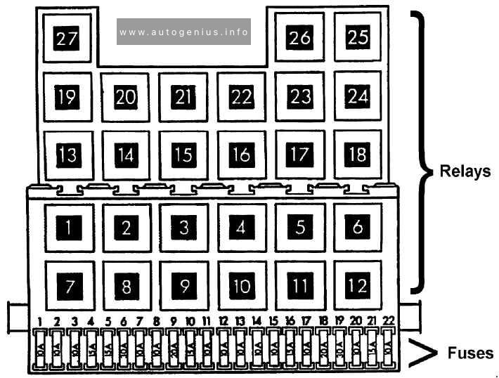
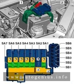
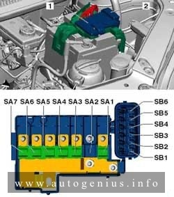
Engine compartment
Fuse box location
This unit is located on the cover in front of the battery.
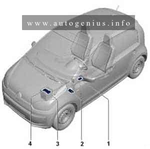
Year of production: 2011, 2012, 2013, 2014, 2015, 2016, 2017
The city car Volkswagen Up is available from 2011 to the present. In this article, you will find fuse box diagrams of Volkswagen Up 2011, 2012, 2013, 2014, 2015, 2016 and 2017, get information about the location of the fuse panels inside the car, and learn about the assignment of each fuse (fuse layout).
Onboard supply control unit -J519-
• Light switch -E1- Dipped beam/daytime running lights/main beam
5
5
7.5*1
Onboard supply control unit -J519-
• Ignition/starter switch -D-
CCS switch -E45-
6
5
7.5*1
Headlight range control regulator -E102-
Left headlight range control motor -V48-
Right headlight range control motor -V49-
Mirror adjustment switch -E43-
7
10
Selector lever -E313-
8
7.5
Automated manual gearbox control unit -J514-
Selector lever -E313-
9
7.5
Airbag control unit -J234-
Centre switch module 2 in dash panel -EX35-
10
5
7.5*1
Parking aid control unit -J446-
11
10
Right headlight dipped beam bulb -M31-
12
5
7.5*1
Dash panel insert -K-
Rear left fog light bulb -L46-
Control unit in dash panel insert -J285-*1
Onboard supply control unit -J519-*1
13
10
Left headlight dipped beam bulb -M29-
14
15
Rear window wiper motor -V12-
15
15
Light switch -E1-
16
5
7.5*1
Terminal 15 voltage supply relay -J329-
Power steering control unit -J500-
17
15
Washer pump switch (automatic wash/wipe and headlight washer system) -E44-