MG MG3 (2013 – 2018) – fuse and relay box diagram
Year of production: 2013, 2014, 2015, 2016, 2917, 2018
This article covers the second-generation MG MG3, following its first facelift, produced from 2013 to 2018. It includes fuse box diagrams for the 2013 to 2018 models, provides information on the locations of the fuse panels inside the vehicle, and details the function of each fuse (fuse layout).
Location
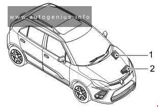
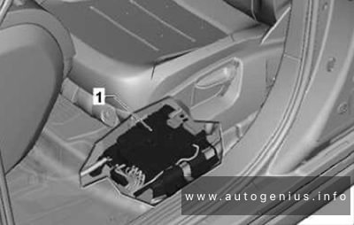
- Passenger Compartment Fuse Box (below the glove box at the front passenger side).
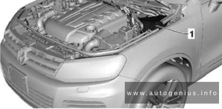
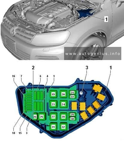
- Engine Compartment Fuse Box (at the left side of the Engine Compartment
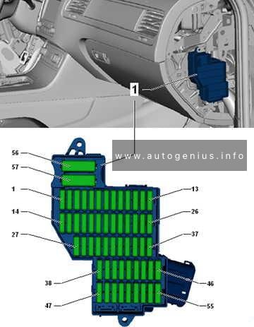
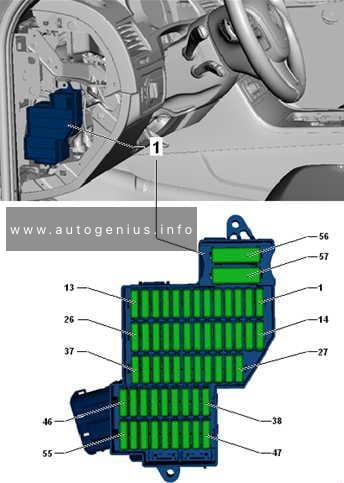
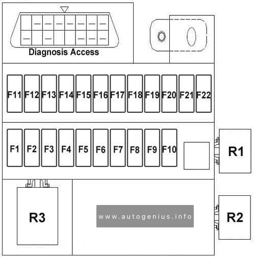
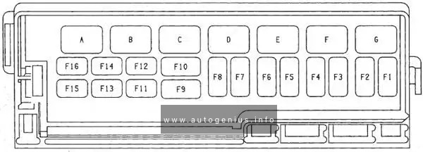
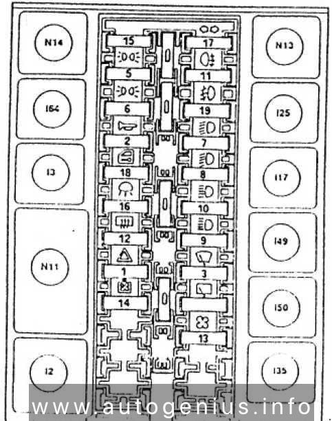
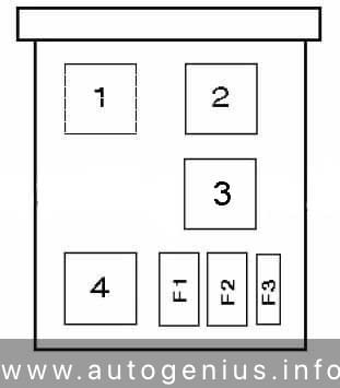
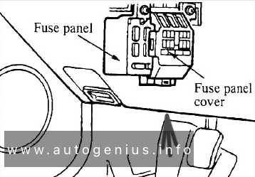
Passenger Compartment Fuse Box
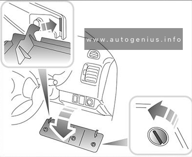
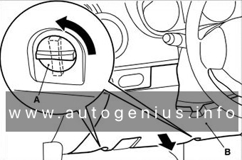
Fuse Box Location
The fuses are located below the glove box at the front passenger side.
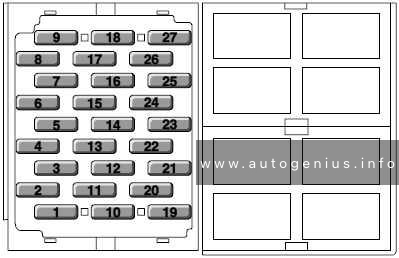
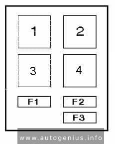
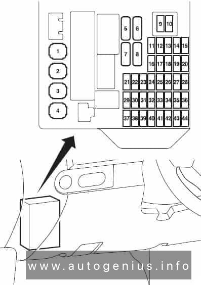
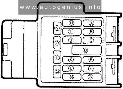
Fuse Box Diagram
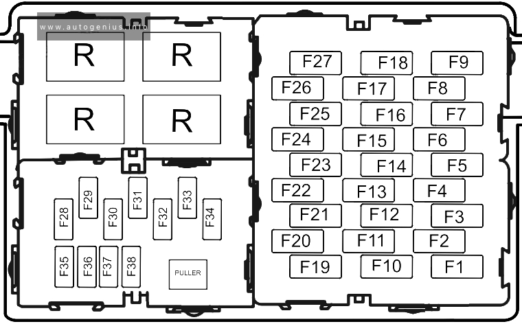
Assignment of the fuses in the passenger compartment
| No. |
А |
Function |
| F1 | 20 | Rear Wiper Relay, Rear Washer Relay (LHD) |
| F2 | 15 | Centre Console Power Socket |
| F3 | 5 | Diagnostic Socket |
| F4 | 5 | ABS, IPK, DC/DC, ECM, BCM, SAS, Yaw Rate Sensor |
| F5 | 10 | Rear Washer Relay (RHD) |
| F6 | 5 | Air Condition, Blower Relay, Centre Console Power Socket Relay, Heated Rear Window Relay, Headlamp Levelling Switch , Passenger Side Airbag Disabled Indicator |
| F7 | 15 | Super Lock Relay |
| F8 | 10 | SRS DCU |
| F9 | 10 | Inertia Switch |
| F10 | 5 | Left Position Lamp, Switch Illumination, Left Tail Lamp |
| F11 | 5 | Front Interior/Map Lamp |
| FI2 | 5 | Rear License Plate Lamp, Right Tail Lamp, Switch Illumination, Right Position Lamp |
| F13 | 20 | Brake Pedal Switch, Reverse Lamp Switch |
| F14 | 15 | CDL Motor (Lock), Tailgate Motor (Lock) |
| FI5 | 10 | Reserve Fuse |
| FI6 | 15 | CDL Motor (Unlock), Tailgate Motor (Unlock) |
| F17 | 10 | Horn |
| FI8 | 10 | BCM, Rear Washer Relay, Driver Door Combination Switch, IPK , In Car Entertainment |
| FI9 | 5 | Left Brake Lamp, High Mounted Brake Lamp |
| F20 | 20 | Left Rear Window Lift Switch |
| F2I | 5 | Right Brake Lamp |
| F22 | 20 | Right Rear Window Lift Switch |
| F23 | 5 | ECM, BCM |
| F24 | 25 | Passenger Window Lift Switch |
| F2S | 20 | Rear Screen ideating |
| F26 | 25 | Driver Door Combination Switch |
| F27 | 10 | Exterior Rear View Mirror Heating |
| F28 | 15 | In Car Entertainment |
| F29 | – | – |
| F30 | 10 | Air Condition |
| F3I | – | – |
| F32 | 10 | IPK |
| F33 | – | – |
| F34 | 5 | DAB |
| F35 | 5 | Reserve Fuse |
| F36 | 10 | Reserve Fuse |
| F37 | 15 | Reserve Fuse |
| F38 | 20 | Reserve Fuse |
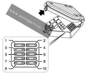
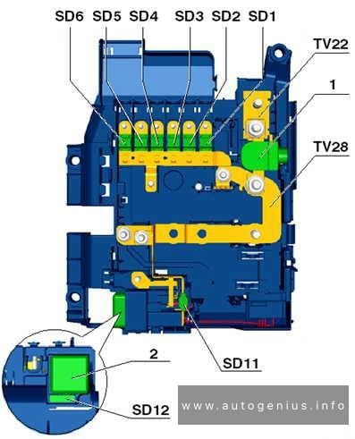
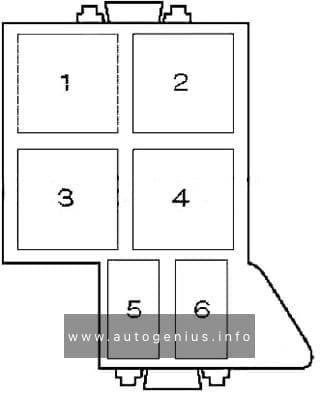
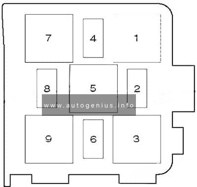
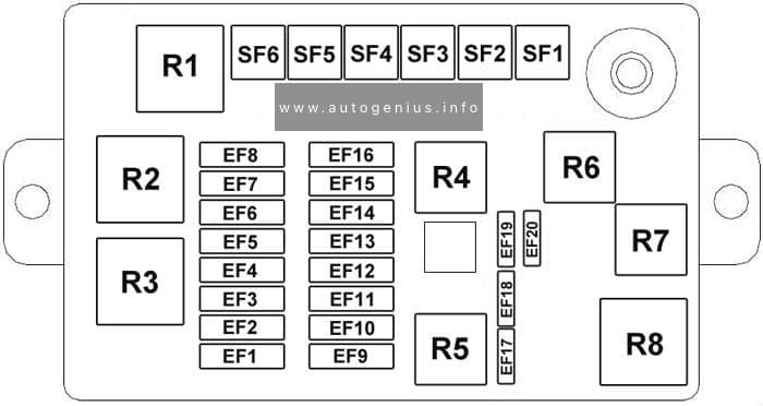
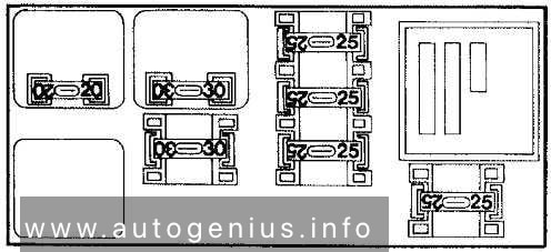
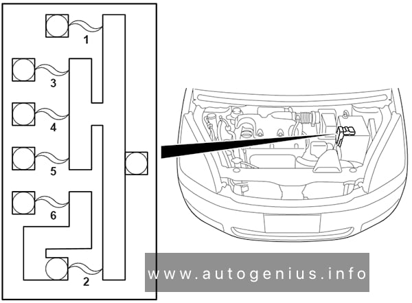
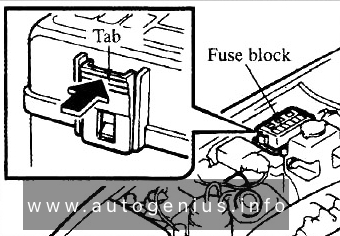
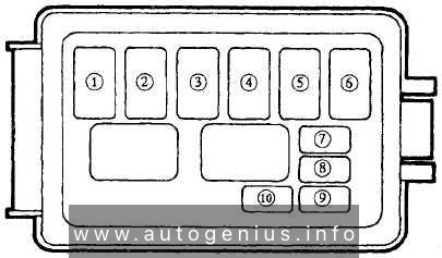
Engine Compartment Fuse Box
Fuse Box Diagram
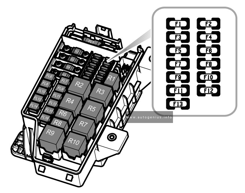
Assignment of the fuses in the engine compartment
| No. |
А |
Function |
| F1 | 10 | Right Front Low Beam Lamp |
| F2 | 5 | Post-Oxygen Sensor, Inlet Cam Solenoid, Exhaust Cam Solenoid |
| F3 | 10 | Left Front Low Beam Lamp |
| F4 | 10 | Air Condition Compressor Clutch |
| F5 | 5 | ECM |
| F6 | 5 | Cooling Fan Relay, Purge Control Valve, Air Condition Compressor Clutch Relay, Fuel Pump Relay, Stop Start Switch |
| F7 | 30 | Front Wiper Enable Relay, Front Wiper Speed Control Relay |
| F8 | 5 | Pre-Oxygen Sensor |
| F9 | 15 | Day Time Running Lamp, IPK Illumination |
| F10 | 10 | Right Front High Beam Lamp, IPK Illumination |
| F11 | 10 | Left Front High Beam Lamp |
| F12 | 30 | Ignition Coils, Injectors, ECM |
| F13 | 30 | – |
| FL1 | 20 | Alternator, Passenger Compartment Fuse Box Fuse F4, FLI 1 |
| FL2 | 50 | SCS ECU (Pump) |
| FL3 | 40 | Cooling Fan |
| FL4 | 60 | Passenger Compartment Fuse Box Fuse F20, F22, F24, F26 |
| FL5 | 80 | Passenger Compartment Fuse Box Fuse FI, F3, F4, F5, F7, F9, F25, F27, Rear Screen Heating Relay |
| FL6 | 25 | SCS ECU (Valve) |
| FL7 | 50 | Ignition Switch |
| FL8 | 25 | Common Unlock and Lock Relays |
| FL9 | 30 | DC/DC Converter |
| FL10 | 25 | Horn Relay, Washer Pump Relay |
| FL11 | 30 | Blower Motor, Air Conditioning |
| FL12 | 25 | Dipped Beam Relay |
| FL13 | 30 | Starter Relay |
| FL14 | 25 | BCM Indicators & Rear Fog Lamp |
| FL15 | 30 | Position Lamp Relay, Day Time Running Lamp Relay, Engine Compartment Fuse Box Fuse F9, FIO, FI 1, Passenger Compartment Fuse Box Fuse FI0, FI2 |
| FL16 | – | – |
WARNING: Terminal and harness assignments for individual connectors will vary depending on vehicle equipment level, model, and market.