Volkswagen e-Golf (2014 – 2020) – fuse and relay box diagram
Year of production: 2014, 2015, 2016, 2017, 2018, 2019, 2020
This article provides the Volkswagen e-Golf, produced from 2014 to the 2020. It provides fuse box diagrams for the Volkswagen e-Golf models from 2014, 2015, 2016, 2017, 2018, 2019, 2029, 2021, and 2022, along with details on the location of the fuse panels within the vehicle. Additionally, it explains the fuse and relay assignments (fuse layout).
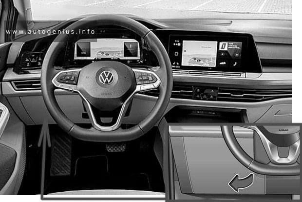
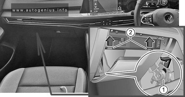
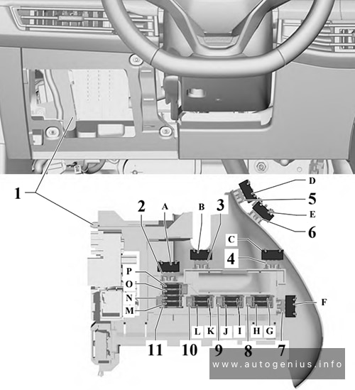
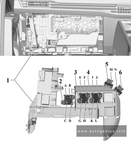
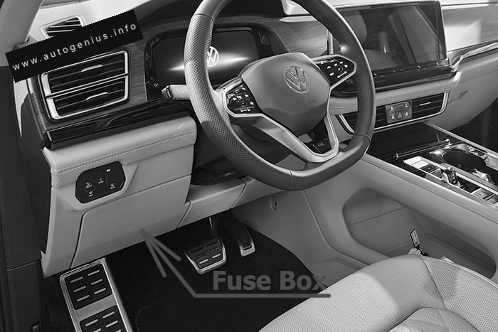
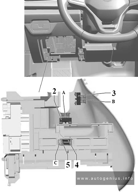
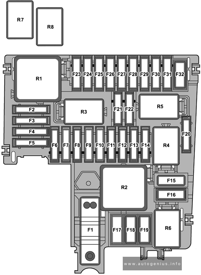
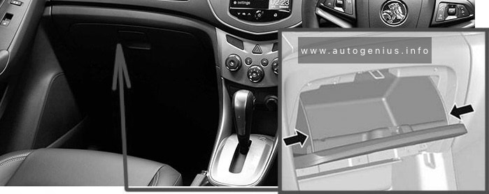
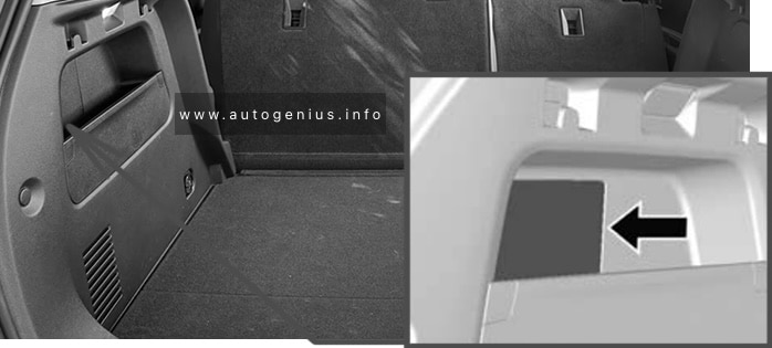
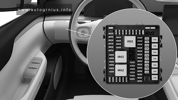
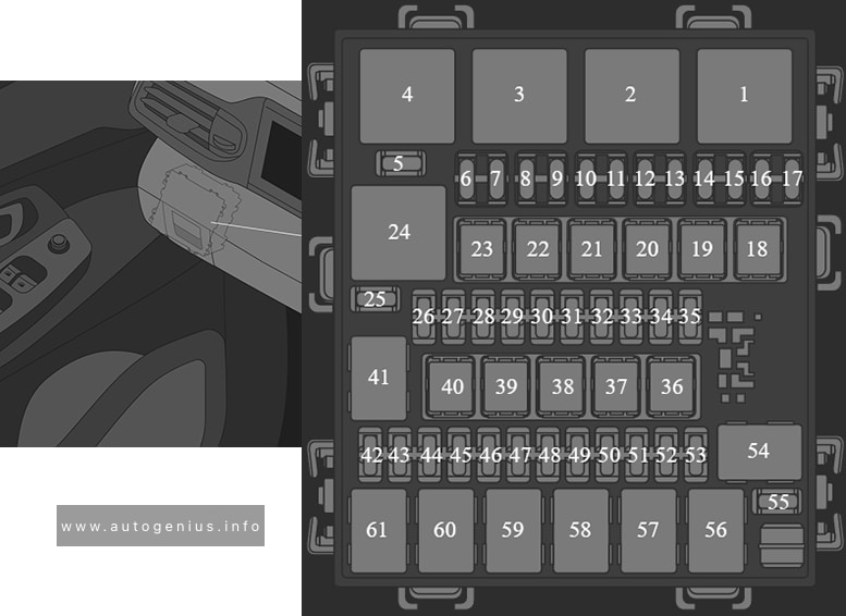
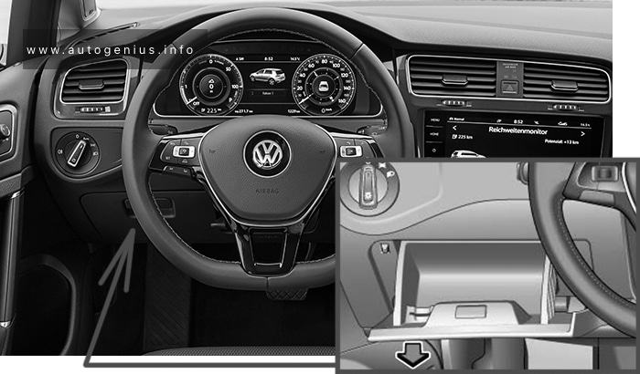
Passenger Compartment Fuse Box
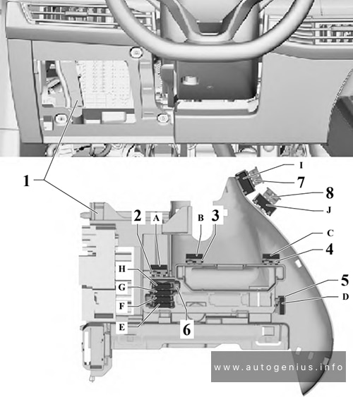
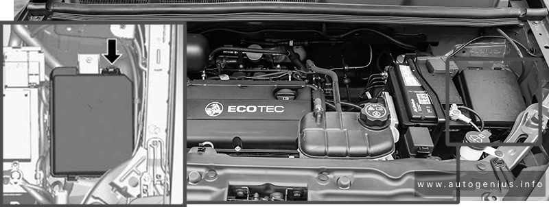
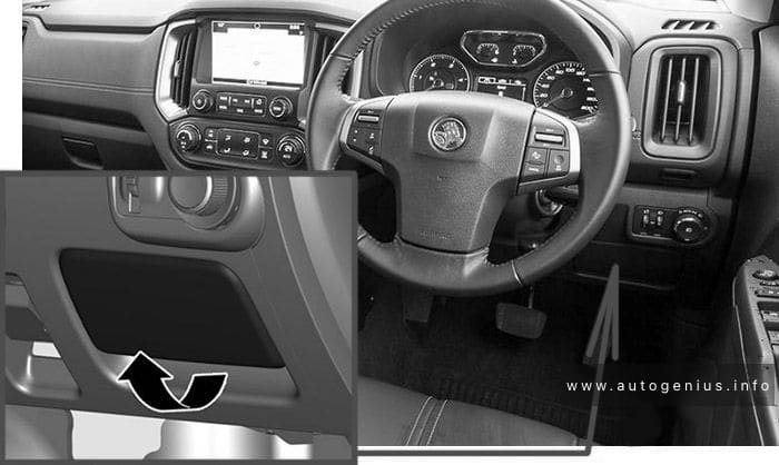
Fuse Box Location
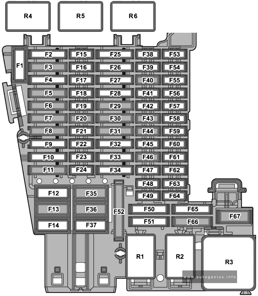
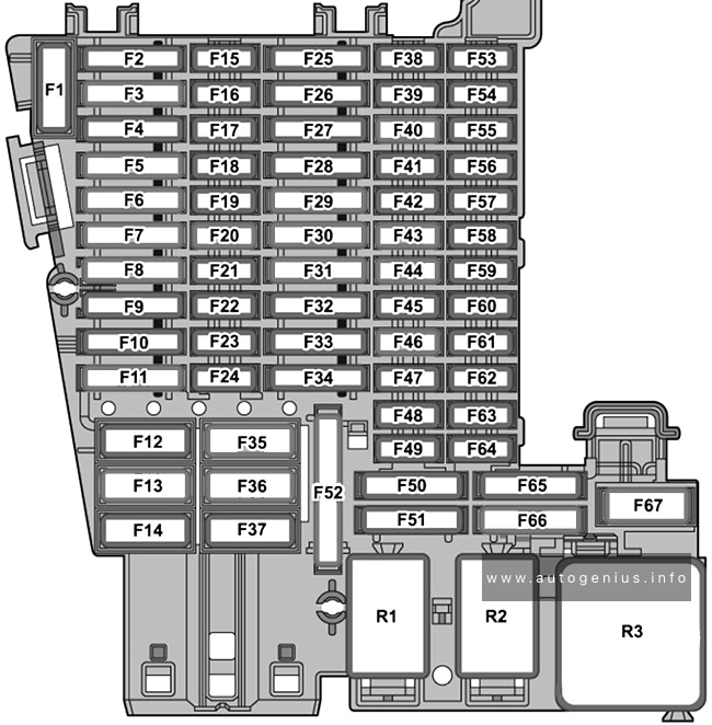
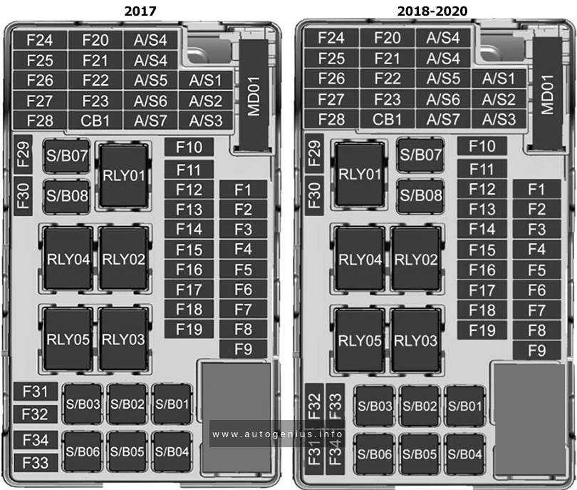
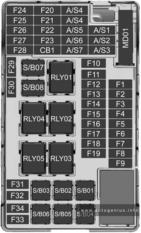
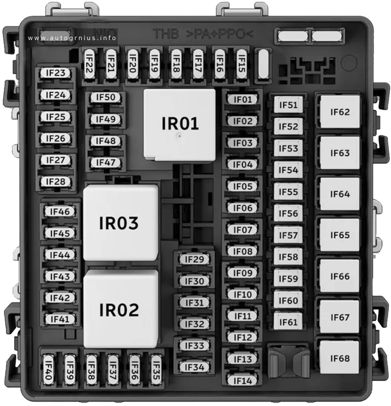
Fuse Box Diagram
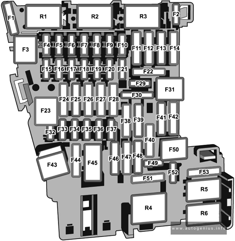
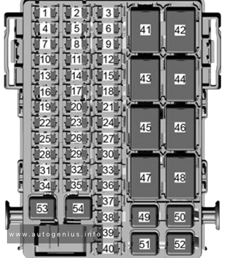
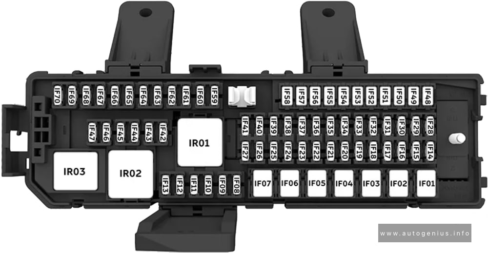
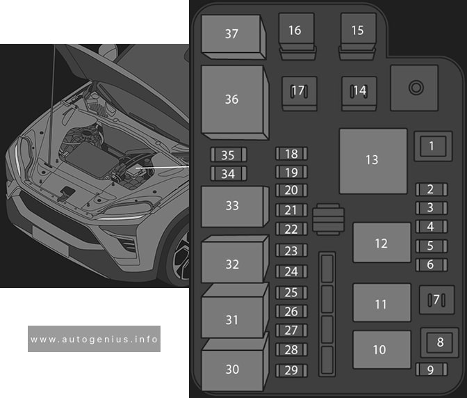
Assignment of the fuses in the passenger compartment (instrument panel -SC-)
| № | Amps | Function / Component |
|---|---|---|
| SC1 | – | – |
| SC2 | – | – |
| SC3 | – | – |
| SC4 | 10A | 2014-2017: Vehicle electrical system control module – Anti-theft alarm system |
| SC4 | 7.5A/10A | 2018-2020: Alarm horn |
| SC5 | 5A/7.5A | Data bus on board diagnostic interface |
| SC6 | 5A | 2014-2015: Anti-theft alarm system sensor2015-2020: Selector lever |
| SC7 | 10A | 2014-2015: Heater and A/C controls Climatronic control module Selector lever Rear window defogger relay2015-2020: Heater and A/C controls Climatronic control module Rear window defogger relay |
| SC8 | 7.5A/10A | 2014-2015: Rotary light switch Electromechanical parking brake button Rain/light recognition sensor Diagnostic connection2015-2020: Rotary light switch Electromechanical parking brake button Rain/light recognition sensor Anti-theft alarm system sensor Diagnostic connection |
| SC9 | 5A/7.5A | Steering column electronics control module |
| SC10 | 10A | Front information display control head |
| SC11 | 25A | 2014-2017: Left front seat belt tensioner control module |
| SC11 | 40A | 2017-2020: Vehicle electrical system control module – Left front headlamp |
| SC12 | 20A | Information electronics control module 1 |
| SC13 | 10A | 2014-2017: High-voltage battery 1 High-voltage system maintenance connector |
| SC13 | 25A | 2017-2020: Left front seat belt tensioner control module |
| SC14 | 30A | Fresh air blower control module |
| SC15 | 10A | Electronic steering column lock control module |
| SC16 | 7.5A | Mobile communication 2-way signal amplifier Telephone baseplate Voltage converter for USB charge module (2014-2015) USB distributor Chip card reader control module TV tuner |
| SC17 | 5A | Instrument cluster Control module for emergency call module and communication unit Telematics Control Module for Real-Time Monitoring (2018-2020 vehicles with China equipment) |
| SC18 | 7.5A | Rearview camera Release button in rear lid handle |
| SC19 | 7.5A | Access/start system interface |
| SC20 | 5A | High-voltage battery charging voltage control module |
| SC21 | – | – |
| SC22 | – | – |
| SC23 | 40A | 2014-2017: Vehicle electrical system control module – Right front headlamp |
| SC24 | 40A | 2017-2020: Vehicle electrical system control module – Right front headlamp |
| SC25 | 30A | Driver Door Control Module (LHD) Left Rear Window Regulator Motor (LHD) Front Passenger Door Control Module (RHD) Right Rear Window Regulator Motor (RHD) |
| SC26 | 30A | Vehicle electrical system control module – Front heated seat |
| SC27 | 30A | 2014-2017: Digital sound system control module2017-2020: Vehicle electrical system control module – Terminal 30 |
| SC28 | – | – |
| SC29 | – | – |
| SC30 | 10A | 2017-2020: High-voltage battery 1 High-voltage system maintenance connector |
| SC31 | 40A | 2014-2017: Vehicle electrical system control module – Left front headlamp |
| SC32 | 7.5A/10A | Driver assistance systems front camera Distance regulation control module Parking Aid Control Module Parallel Parking Assistance Control Module Blind spot detection control module Blind spot detection control module 2 |
| SC33 | 5A/7.5A | Airbag control module Front passenger airbag -disabled- indicator lamp |
| SC34 | 7.5A | Rotary light switch Interior rearview mirror Sockets relay Air quality sensor Electromechanical parking brake button |
| SC35 | 7.5A/10A | Diagnostic connection Headlamp Range Control and Instrument Illumination Regulator Cornering lamp and headlamp range control module |
| SC36 | 5A | 2014-2018: Right LED headlamp power output module 1 |
| SC36 | 10A | 2018-2020: Right front headlamp – Right LED headlamp power output module 1 – Right Headlamp Power Output Module – Left Light Control Module |
| SC37 | 5A | 2014-2018: Left LED headlamp power output module 1 |
| SC37 | 10A | 2018-2020: Left front headlamp – Left LED headlamp power output module 1 – Left Headlamp Power Output Module – Right Light Control Module |
| SC38 | – | – |
| SC39 | 30A | Front Passenger Door Control Module (LHD) Right Rear Window Regulator Motor (LHD) Driver Door Control Module (RHD) Left Rear Window Regulator Motor (RHD) |
| SC40 | 20A | Cigarette Lighter 12V socket -U5- 12V socket 2 -U18- From the factory, fuse SC40 is supplied by terminal 15 and can be supplied by terminal 30 instead, if equipment is connected to the socket or the cigarette lighter, make sure the equipment is disconnected from the power supply when the engine is off to prevent the battery from draining. |
| SC41 | 25A | Right front seat belt tensioner control module |
| SC42 | 40A | Vehicle electrical system control module – Central locking system |
| SC43 | 30A | 2014-2017: Vehicle electrical system control module – Terminal 302017-2020: Digital sound system control module |
| SC44 | – | – |
| SC45 | 15A | Left Front Seat Adjustment Control Head |
| SC46 | – | – |
| SC47 | 15A | Rear window wiper motor |
| SC48 | 7.5A | Engine sound generator control module |
| SC49 | 5A/7.5A | High-voltage battery charging voltage control module |
| SC50 | – | – |
| SC51 | – | – |
| SC52 | – | – |
| SC53 | 30A | Rear window defogger relay |
| Relays | ||
| R1 | – | |
| R2 | – | |
| R3 | – | |
| R4 | Power supply (terminal 15) | |
| R5 | Rear Window Defogger | |
| R6 | Sockets |
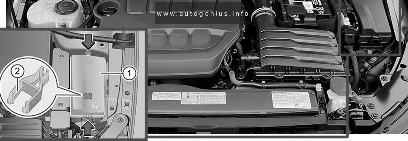
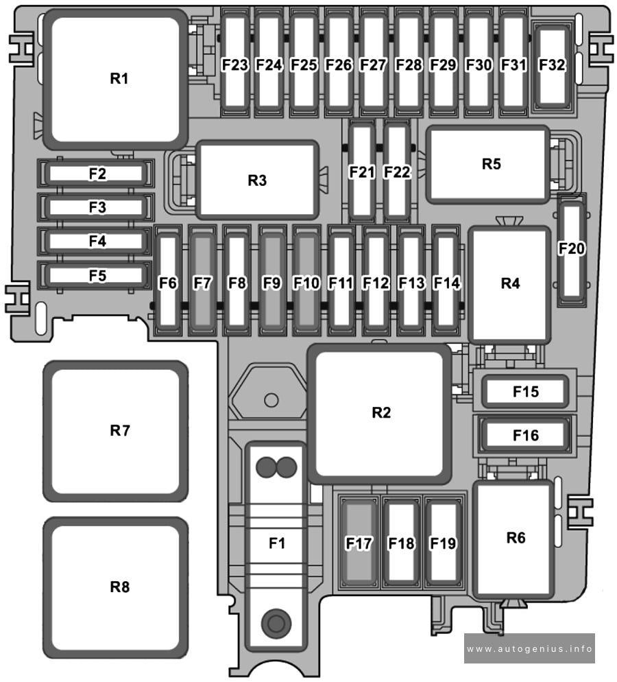
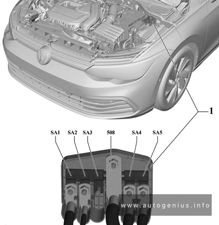
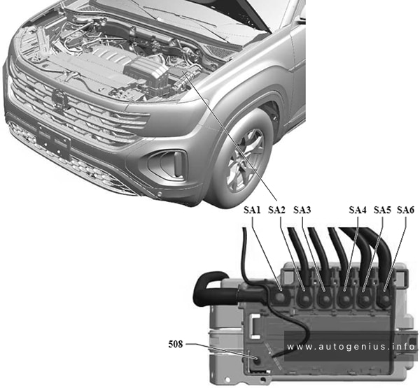
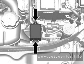
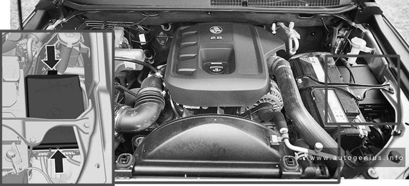
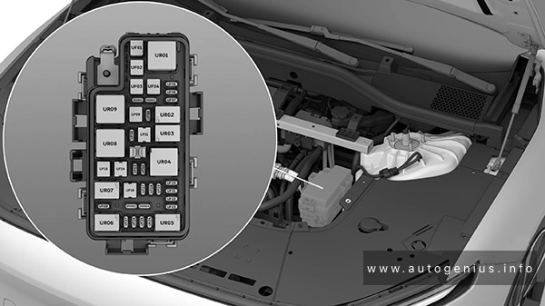
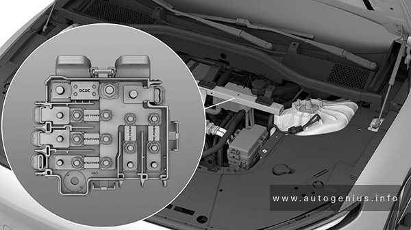
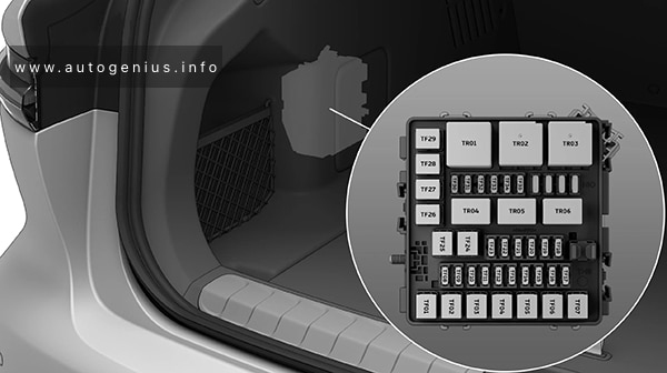
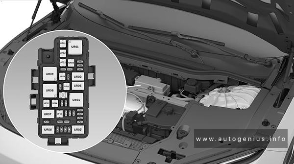
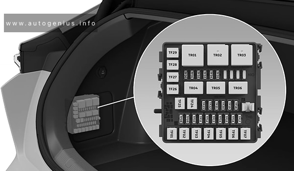
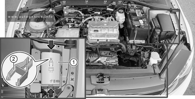
Engine Compartment Fuse Box
Fuse Box Location
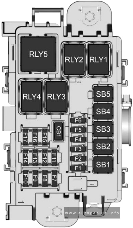
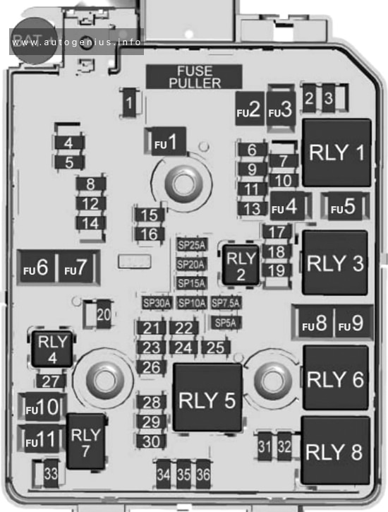
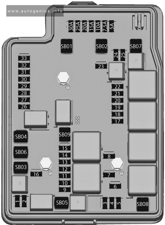
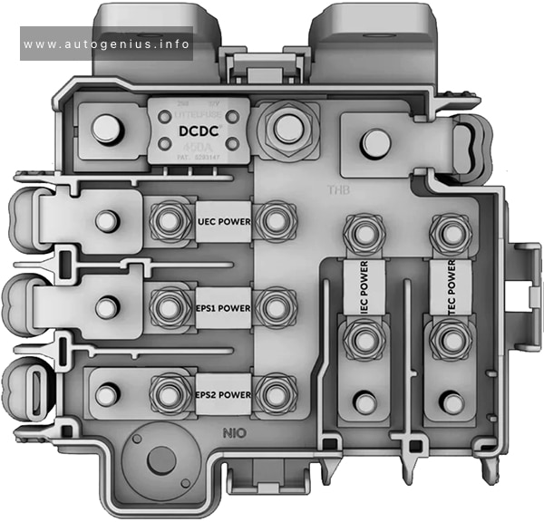
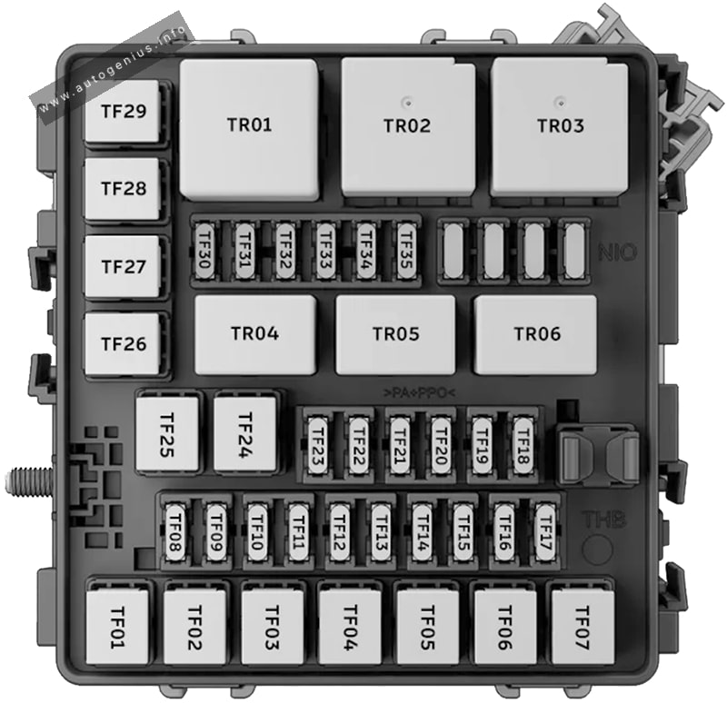
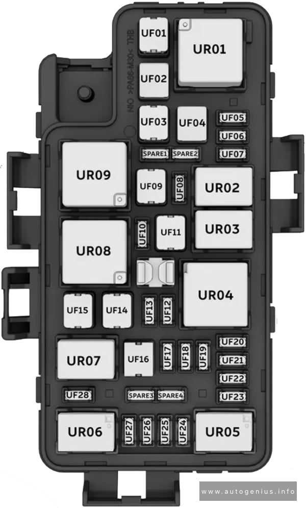
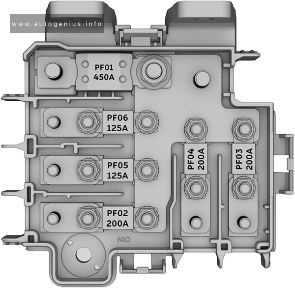
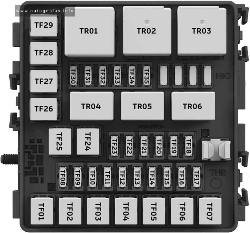
Fuse Box Diagram
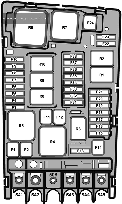
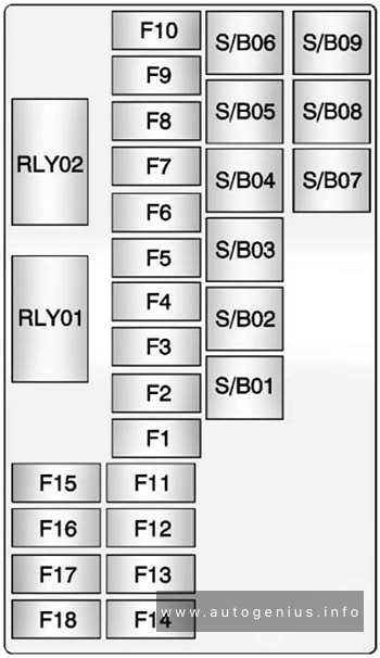
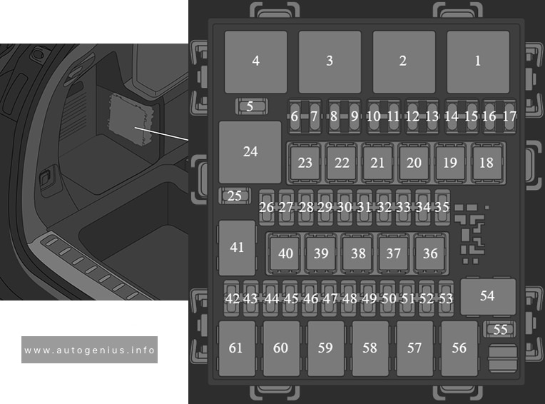
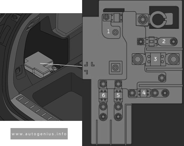
Assignment of the fuses in the engine compartment fuse box (-SA-, -SB-)
| № | Amps | Function / Component |
|---|---|---|
| SA1 | 125A | Fuses (Instrument panel): 4, 5, 6, 7, 8, 9, 10, 11, 12, 13, 14, 31, 39, 41, 42, 53 Sockets relay Power supply relay terminal 15 |
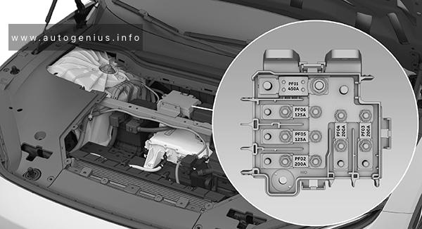
| SA2 | 400A | Electric drive power and control electronics |
| SA3 | 80A | Power steering control module |
| SA4 | 80A | Fuses (Instrument panel): 15, 16, 17, 18, 19, 20, 23, 24, 25, 26, 27, 43 |
| SA5 | 50A | Radiator fan |
| 508 | – | Battery Positive terminal |
| SB1 | 25A/40A | ABS control module |
| SB2 | 40A | ABS control module – ABS hydraulic pump |
| SB3 | 15A | Engine control module |
| SB4 | 5A | Radiator fan Radiator bypass switch-over valve |
| SB5 | – | – |
| SB6 | – | – |
| SB7 | 10A | Radiator shutter motor Water pump Coolant pump in front of high-voltage heater (PTC) |
| SB8 | – | – |
| SB9 | – | – |
| SB10 | – | – |
| SB11 | 40A | Brake booster |
| SB12 | – | – |
| SB13 | 7.5A | 2018-2020: Brake booster |
| SB14 | 40A | Windshield defogger relay |
| SB15 | 15A | Horn relay |
| SB16 | 10A | High-voltage battery charger 1 Electric drive power and control electronics |
| SB17 | 7.5A | Motronic engine control module power supply relay Engine control module ABS control module Windshield defogger relay Terminal 15 load reduction relay (2014-2016) |
| SB18 | 5A | Battery monitoring control module |
| SB19 | 30A | Wiper motor control module |
| SB20 | 10A | Alarm horn |
| SB21 | – | – |
| SB22 | – | – |
| SB23 | – | – |
| SB24 | – | – |
| SB25 | – | – |
| SB26 | – | – |
| SB27 | – | – |
| SB28 | – | – |
| SB29 | – | – |
| SB30 | – | – |
| SB31 | – | – |
| SB32 | – | – |
| SB33 | 30A | Brake system pressure reservoir |
| SB34 | 5A | 2014-2018: Brake booster |
| SB35 | 7.5A | A/C relay Thermal management control module |
| SB36 | – | – |
| SB37 | – | – |
| SB38 | – | – |
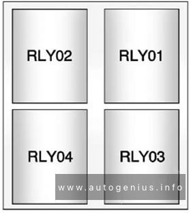
| Relays | ||
| R1 | – | |
| R2 | – | |
| R3 | Horn | |
| R4 | Brake Booster Vacuum Sensor link | |
| R5 | Main relay | |
| R6 | 2014-2016: Terminal 15 load reduction |
|
| R7 | – | |
| R8 | A/C relay | |
| R11 | Windshield defogger |
WARNING: Terminal and harness assignments for individual connectors will vary depending on vehicle equipment level, model, and market.