Cadillac Eldorado (1992 – 1993) – fuse and relay box diagram
Year of production: 1992, 1993
This article covers the Cadillac Eldorado, produced from 1953 to 2002. The Cadillac Eldorado was one of the longest-produced luxury coupé models in the history of American automotive manufacturing.
Inside, you’ll find fuse box diagrams for the 1992 and 1993 models, along with details on the location of the fuse panels within the vehicle and information on the function and layout of each fuse and relay.
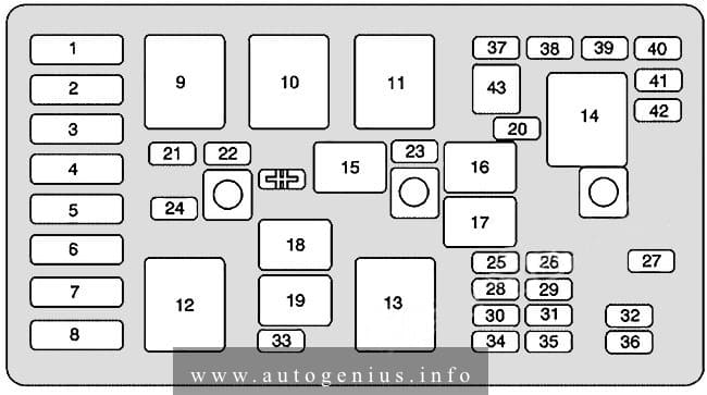
Engine compartment
Maxi Fuse/Relay Center
The maxi fuse and relays are located next to the engine compartment fuse block.
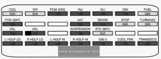
Assignment of the fuses in the engine compartment
| Fuse name | Ampere rating [A] | Usage |
| COIL | 20 | 4.9L DISTRIBUTOR, 4.6L IGNITION CONTROL MODULE |
| SIR | 20 | DIAGNOSTIC ENERGY RESERVE MODULE (DERM) SIR (AIR BAG), ARMING SENSOR |
| PCM (IGN) | 10 | POWERTRAIN CONTROL MODULE (PCM), PASSKey DECODER MODULE |
| INJ | 10 | FUEL INJECTORS 1,4,6,7 |
| INJ | 10 | FUEL INJECTORS 2,3,5, |
| IGN | 10 | A/C COMPRESSOR, ELECTROCHROMIC MIRROR, INSTRUMENT PANEL CLUSTER, DIAGNOSTIC ENERGY RESERVE MODULE (DERM) SIR (AIR BAG), KEYLESS ENTRY MODULE, CORNERING LIGHTS, CHIME MODULE, TWILIGHT SENTINEL/DRL MODULE, BACKUP LIGHTS, BRAKE TRANSMISSION SHIFT INTERLOCK |
| FUEL | 20 | FUELPUMP, POWERTRAIN CONTROL MODULE |
| PCM (BAT) | 10 | POWERTRAIN CONTROL MODULE (PCM) |
| A/C | 10 | A/C COMPRESSOR |
| HTD W/S | 10 | HEATED WINDSHIELD |
| STOP LP | 20 | STOP LIGHTS |
| TURN/HAZ | 20 | HAZARD LIGHTS, TURN SIGNAL LIGHTS |
| DRL (CANADA) | 10 | DAYTIME RUNNING LIGHTS |
| DRL (CANADA) | 10 | DAYTIME RUNNING LIGHTS |
| SUSPENSION | 10 | ROAD SENSING SUSPENSION, SPEED SENSITIVE SUSPENSION (4.9L) |
| RTD (BAT) | 20 | ROAD SENSING SUSPENSION |
| L HDLP LO (EXPORT) | 10 | LEFT HEADLAMP LOW BEAM |
| R HDLP LO (EXPORT) | 10 | RT HEADLAMP LOW BEAM |
| L HDLP HI (EXPORT) | 10 | LEFT HEADLAMP HIGH BEAM |
| R HDLP HI (EXPORT) | RIGHT HEADLAMP HIGH BEAM | |
| IGN 3 | 10 | HEATED WINDSHIELD, HEATER AND A/C PROGRAMMER, ELECT. LEVEL CONTROL (ELC), DEFOGGER RELAY “D”, CRUISE CONTROL, POWERTRAIN CONTROL MODULE |
| COOLING FAN | 10 | COOLING FANS, POWERTRAIN CONTROL MODULE (4.6L), FRONT AND REAR HEATED OXYGEN SENSOR (4.6L) |
| TRANS/ECS | 10 | EXHAUST GAS RECIRCULATION (EGR), POWERTRAIN CONTROL MODULE (PCM), AUTOMATIC TRANSAXLE, EVAPORATIVE EMISSION CONTROL SOLENOID, OVERSPEED ALERT MODULE (EXPORT), POWER STEERING PRESSURE SWITCH |
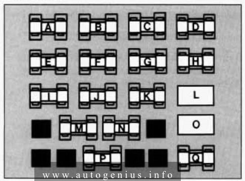
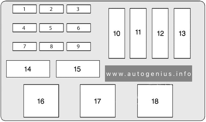
MAXI Fuse block
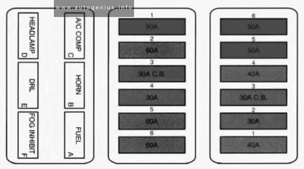
LH MAXI FUSE BLOCK
Assignment of the fuses in the engine compartment (LH maxi fuse block)
| Fuse number | Fuse name | Ampere rating [A] | Usage |
| 1 | 50 | RETAINED ACCESSORY POWER (RADIO/WIPERS), STARTER, TRUNK COMR FUSE A11, ENGINE COMP FUSES A1, A3, A5, A7, A9, A11, A13 | |
| 2 | U.S.A./CANADA Z49/SAUDI | 60 | TRUNK COMP FUSES C1, C3, C5, C7, C9, C11, ROAD SENSING SUSPENSION |
| EXPORT EXCEPT SAUD | 60 | ROAD SENSING SUSPENSION, REAR FOG LIGHT (EXPORT), TRUNK COMP FUSES C1, C3, C5, C7, C9, C11, C13 |
|
| 3 | CIRCUIT BREAKER | 30 | TRUNK RELEASE, LEFT AND RIGHT POWER SEAT, LEFT AND RIGHT LUMBAR CONTROL, KEYLESS ENTRY MODULE, POWER DOOR LOCKS, HORNS |
| 4 | 30 | POWERTRAIN CONTROL MODULE (PCM), ELECTRONIC CLIMATE CONTROL, RAP/ILLUMINATED ENTRY MODULE, INSTRUMENT PANEL CLUSTER, PASSKey DECODER MODULE, THEFT DETERRENT | |
| 5 | 60 | LEFT AND RIGHT HEATED SEATS, ELECTRONIC LEVEL CONTROL (ELC), TRUNK LID PULL DOWN, POWER ANTENNA, REAR DEFOGGER, LEFT AND RIGHT MIRROR DEFOGGERS | |
| 9 | 60 | RETAINED ACCESSORY POWER (SUNROOF/POWER WINDOWS), ENGINE COMP. FUSES C7, D1, D3, D5, TRUNK COMF! FUSES A1, A3, A5, A7 |
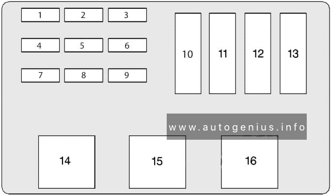
RH MAXI FUSE BLOCK
Assignment of the fuses in the engine compartment (RH maxi fuse block)
| Fuse numeber | Fuse name | Ampere rating [A] | Usage |
| 1 | FUSE | 40 | TURN/HAZ STOP LP, PARK LIGHTS |
| 2 | FUSE | 30 | DELCO-BOSEG SPEAKERS, RADIO CONTROL HEAD, REMOTE RADIO RECEIVER |
| 3 | CIRCUIT BREAKER | 30 | FLASH TO PASS FEATURE, DAYTIME RUNNING LIGHT (DRL), HEADLIGHTS |
| 4 | HAVAC BLOWER | 40 | HVAC POWER MODULE, A/C COMPRESSOR |
| 5 | ABS | 50 | ANTILOCK BRAKE PRESSURE VALVE |
| 6 | COOLING FANS | 50 | COOLING FANS |
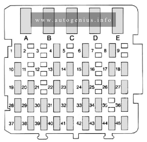
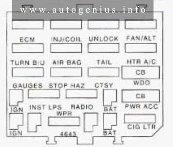
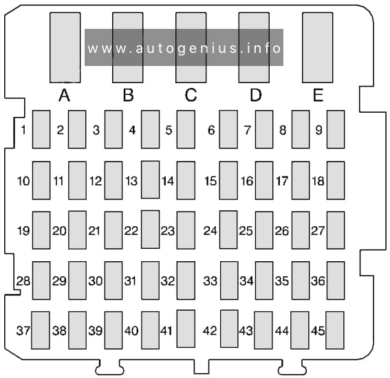
Rear Compartment Fuse Block
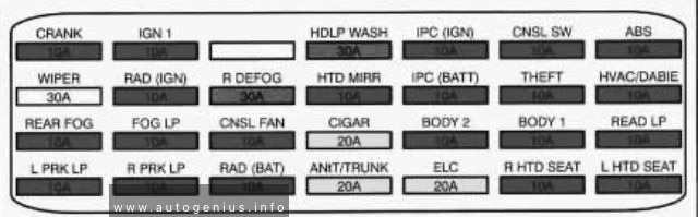
Assignment of the fuses in the rear compartment
| Fuse name | Ampere rating [A] | Usage |
| CRANK | 10 | RAP/ILLUMINATED ENTRY MODULE, DIAGNOSTIC ENERGY RESERVE MODULE (DERM), STARTER |
| IGN 1 | 10 | CATALYTIC CONVERTER ALARM MODULE (EXPORT), FUEL LEVEL SENSOR, ELECTROCHROMIC MIRROR, THEFT DETERRENT MODULE, KEYLESS ENTRY MODULE, TURN SIGNAL LIGHTS, RAP/ILLUMINATED ENTRY MODULE |
| HDLP WASH (EXPORT) | 30 | HEADLIGHT WASHER MODULE |
| IPC (IGN) | 10 | INSTRUMENT PANEL CLUSTER |
| CNSL SW | 10 | REAR BLOWER MOTOR, CONSOLE SWITCH |
| ABS | 10 | ELECTRONIC BRAKE CONTROL MODULE (4.9L), ELECTRONIC BRAKE AND TRACTION CONTROL, MODULE (NORTHSTAR) |
| WIPER | 30 | WIPER/WASHER SWITCH |
| RAD (IGN) | 10 | REMOTE RADIO RECEIVER |
| R DEFOG | 30 | REAR DEFOGGER |
| HTD MlRR | 10 | RIGHT AND LEFT POWER MIRROR-DEFOGGER |
| IPC (BATT) | 10 | INSTRUMENT PANEL CLUSTER |
| THEFT | 10 | PASS-Key@ DECODER MODULE, THEFT DETERRENT RELAY, THEFT DETERRENT MODULE |
| HVACIDABIE | 10 | HEATER AND A/C PROGRAMMER, RAP/ILLUMINATED ENTRY MODULE |
| REAR FOG (EXPORT) | 10 | REAR FOG LIGHTS |
| FOG LP (4.6L) | 10 | FOG LIGHTS |
| CNSL FAN | 10 | REAR BLOWER MOTOR |
| CIGAR | 20 | REAR CIGAR LIGHTERS-SEVILLE ONLY, FRONT CIGAR LIGHTER, CHIME MODULE |
| BODY 2 | 10 | POWER MIRROR SWITCH, RETAINED ACCESSORY POWER, TRUNK LIGHT, CONSOLE SWITCH, PANEL LIGHTS INHIBIT (EXPORT), COURTESY LIGHTS, KEYLESS ENTRY MODULE |
| BODY 1 | 10 | POWER DOOR LOCKS, DOOR LOCK CYLINDER ILLUMINATION, GLOVE BOX LIGHT, FOOTWELL LIGHTS, TWILIGHT SENTINEUDRL MODULE, HEADLIGHT SWITCH |
| READ LP | 10 | LEFT AND RIGHT VANITY MIRRORS, GARAGE DOOR OPENER, FRONT AND REAR HEADER LIGHTS |
| L PRK LP | 10 | RADIO DIMMING, HEADLIGHT SWITCH, INSTRUMENT PANEL CLUSTER, LEFT MARKER LIGHT, LEFT TAIL/STOP/TURN LIGHTS, LEFT PARWTURN LIGHT |
| R PRK LP | 10 | RIGHT MARKER LIGHTS, LICENSE LIGHTS, RIGHT PARWURN LIGHT, ENGINE COMPARTMENT LIGHT, RIGHT TAlL/STOP/TURN LIGHTS |
| RAD (BAT) | 10 | REMOTE RADIO RECEIVER, RADIO CONTROL HEAD |
| ANT/TRUNK | 20 | TRUNK PULL DOWN, POWER ANTENNA |
| ELC | 20 | ELECTRONIC LEVEL CONTROL |
| R HTD SEAT | 10 | PASSENGERS HEATED SEAT |
| L HTD SEAT | 10 | DRIVERS HEATED SEAT |
WARNING: Terminal and harness assignments for individual connectors will vary depending on vehicle equipment level, model, and market.