Lincoln Navigator (UN173; 1999) – fuse and relay box diagram
Year of production: 1999
This article covers the first-generation Lincoln Navigator, manufactured between 1998 and 2002. It includes fuse box diagrams for the 1999 models, provides details on the locations of the fuse panels within the vehicle, and explains the function and layout of each fuse and relay.
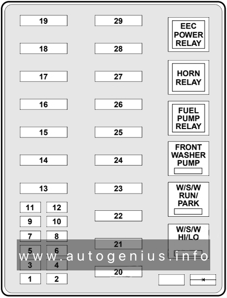
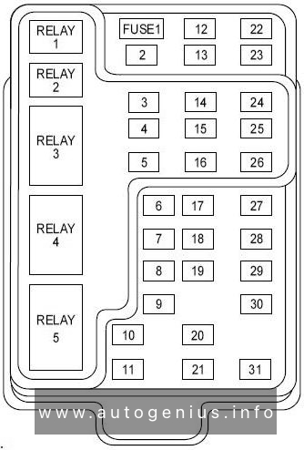
Passenger compartment fuse panel
Fuse box location
The fuse panel is located below and to the left of the steering wheel behind the cover.
Fuse box diagram

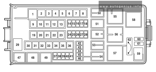
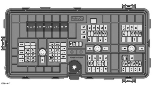
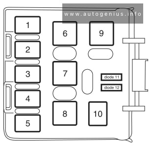
Lincoln Navigator (UN173; 1999) – fuse and relay box diagram – passenger compartment
Assignment of the fuses and relays in the passenger compartment (1999)
| No. |
A |
Circuit Protected |
| 1 | 25A | Audio |
| 2 | 5A | Clock, Overhead Trip Computer, Electronic Automatic Temperature Control (EATC), Powertrain Control Module (PCM), Cluster |
| 3 | 20A | Cigar Lighter, OBD-II Scan Tool Connector |
| 4 | 15A | Autolamp Module, Remote Entry Module, Mirrors, Memory Module, Adjustable Pedals, Air Suspension Switch |
| 5 | 15A | AC Clutch Relay, Speed Control Module, Reverse Lamp, EVO Module, Climate Mode Switch, Daytime Running Lamp Relay |
| 6 | 5A | Cluster, Overhead Trip Computer, Compass, Steering Sensor, Brake Shift Interlock Solenoid, Air Suspension Module, GEM Module |
| 7 | 5A | Aux A/C Blower Relay, Console Blower |
| 8 | 5A | Radio, Remote Entry Module, Cell Phone, Clock, GEM Module |
| 9 | — | Not Used |
| 10 | — | Not Used |
| 11 | 30A | Front Washer Pump Relay, Wiper Run/Park Relay, Wiper Hi/LO Relay, Windshield Wiper Motor, Rear Washer Pump Relay |
| 12 | — | Not Used |
| 13 | 20A | Stop Lamp Switch (Lamps), Turn/Hazard Flasher, Speed Control Module |
| 14 | 15A | Rear Wipers, Running Board Lamps, Batteiy Saver Relay, Interior Lamp Relay, Accessory Delay Relay (Power Windows, Flip Windows, Audio) |
| 15 | 5A | Stop Lamp Switch, (Speed Control, Brake Shift Interlock, ABS, PCM Module Inputs), GEM Module |
| 16 | 20A | Headlamps (Hi Beams), Cluster (Hi Beam Indicator) |
| 17 | 10A | Heated Mirrors/Rear Window Defroster Indicator |
| 18 | 5A | Instrument Illumination (Dimmer Switch Power), Clock (Dimmer) |
| 19 | — | Not Used |
| 20 | 5A | Audio, Four Wheel Air Suspension (4WAS) Module, Memory Module, GEM Module, Digital Transmission Range Selector |
| 21 | 15A | Starter Relay, Fuse 20 |
| 22 | 10A | Air Bag Module |
| 23 | 10A | Electrochromic Mirror, Aux A/C, Heated Seats, Trailer Tow Battery Charge, Turn/Hazard Flasher, Console Blower Door Actuator |
| 24 | 10A | Climate Mode Switch (Blower Relay), EATC (via fuse 7), EATC Blower Relay |
| 25 | 5A | 4 Wheel Anti-Lock Brake System (4WABS) Module |
| 26 | 10A | Right Side Low Beam Headlamp |
| 27 | 5A | Foglamp Relay and Foglamp Indicator |
| 28 | 10A | Left Side Low Beam Headlamp |
| 29 | 5A | Autolamp Module, Transmission Overdrive Control Switch |
| 30 | 30A | Passive Anti Theft Transceiver, Cluster, Ignition Coils, Powertrain Control Module Relay |
| 31 | 10A | Rear Integrated Control Panel (Audio), CD Player, Cell Phone |
| Relay 1 | — | Interior Lamp Relay |
| Relay 2 | — | Battery Saver Relay |
| Relay 3 | — | Rear Window Defroster Relay |
| Relay 4 | — | One Touch Down Wmdow Relay |
| Relay 5 | — | ACC Delay Relay |
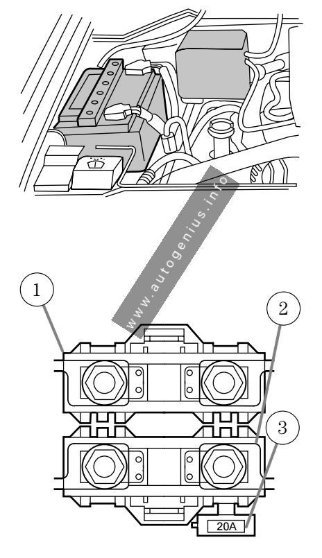
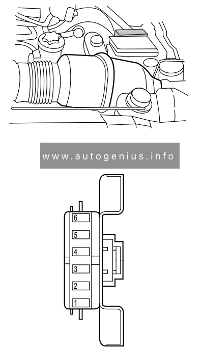
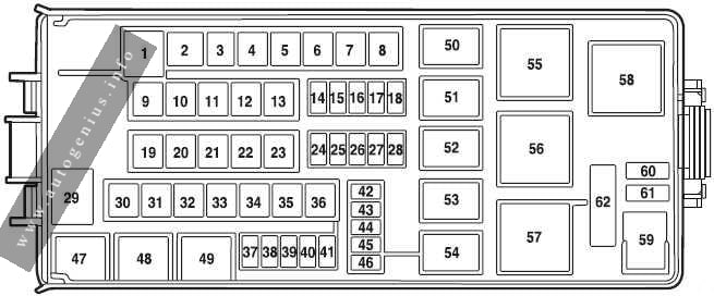
Engine Compartment Fuse Box
Fuse box location
The power distribution box is located in the engine compartment (on the driver’s side).
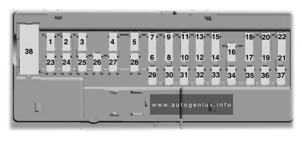
Fuse box diagram

Assignment of the fuses and relays in the engine compartment (1999)
| № | Amp Rating | Description |
|---|---|---|
| 1 | 25A | Power Point |
| 2 | 30A | Powertrain Control Module |
| 3 | 30A | Headlamps/Autolamps |
| 4 | 25A | Console PowerPoint |
| 5 | 20A | Trailer Tow Backup/Park Lamps |
| 6 | 15A | Parklamps/Autolamps |
| 7 | 20A | Horn |
| 8 | 30A | Power Door Locks |
| 9 | 15A | Daytime Running Lamps (DRL), Fog Lamps |
| 10 | 20A | Fuel Pump |
| 11 | 20A | Alternator Field |
| 12 | 10A | Rear Wipers |
| 13 | — | Not Used |
| 14 | — | Not Used |
| 15 | 10A | Running Board Lamps |
| 16 | — | Not Used |
| 17 | 10A | Delayed Accessory (Audio, Moonroof) |
| 18 | 15A | Powertrain Control Module, Fuel Injectors, Fuel Pump, Mass Air Flow Sensor |
| 19 | 10A | Trailer Tow Stop and Right Turn Lamp |
| 20 | 10A | Trailer Tow Stop and Left Turn Lamp |
| 21 | — | Not Used |
| 22 | — | Not Used |
| 23 | 15A | Powertrain Control Module, HEGO Sensors, Canister Vent |
| 24 | 15A | Powertrain C ontrol Module, Transmission, CMS Sensor |
| 101 | 30A | Trailer Tow Battery Charge |
| 102 | 50A | Four Wheel Antilock Brake Module |
| 103 | 50A | Junction Box Battery Feed |
| 104 | 30A | 4×4 Shift Motor & Clutch |
| 105 | 40A | Climate Control Front Blower |
| 106 | — | Not Used |
| 107 | 30A | Passenger Power Seat |
| 108 | 30A | Trailer Tow Electric Brake |
| 109 | 50A | Air Suspension Compressor |
| 110 | 30A | Moonroof, Flip Windows and Heated Seats |
| 111 | 50A | Ignition Switch Battery Feed (Run and Start Circuits) |
| 112 | 30A | Memory (Drivers Seat, Adjustable Pedals, Mirrors) |
| 113 | 50A | Ignition Switch Batteiy Feed (Run and Accessory Circuits) |
| 114 | 30A | Climate Control Auxilary Blower |
| 115 | — | Not Used |
| 116 | 40A | Rear Window Defroster, Heated Mirrors |
| 117 | — | Not Used |
| 118 | — | Not Used |
| 201 | — | Trailer Tow Park Lamp Relay |
| 202 | — | Front Wiper Run/Park Relay |
| 203 | — | Trailer Tow Backup Lamp Relay |
| 204 | — | A/C Clutch Relay |
| 205 | — | Horn Relay |
| 206 | — | Fog Lamp Relay |
| 207 | — | Front Washer Pump Relay |
| 208 | — | Rear Washer Pump Relay |
| 209 | — | Front Wiper Hi/Lo Relay |
| 210 | — | Not Used |
| 211 | — | Not Used |
| 212 | — | Rear Wiper Up Relay |
| 213 | — | Rear Wiper Down Relay |
| 301 | — | Fuel Pump Relay |
| 302 | — | Trailer Tow Battery Charge Relay |
| 303 | — | Not Used |
| 304 | — | Powertrain Control Module Relay |
| 401 | — | Not Used |
| 501 | — | Powertrain Control Module Diode |
| 502 | — | A/C Clutch Diode |
| 503 | — | Not Used |
| 601 | 30A | Delayed Accessory (Power Windows, Flip Windows, Radio) |
| 602 | — | Not Used |
WARNING: Terminal and harness assignments for individual connectors will vary depending on vehicle equipment level, model, and market.