Ford F-750 (2023) – fuse and relay box diagram
Year of production: 2023
This article focuses on the facelifted eighth-generation Ford F-650 and F-750, produced from 2021 to the present. It includes fuse box diagrams for the 2023 models, provides information on the locations of the fuse panels within the vehicle, and outlines the function and layout of each fuse.
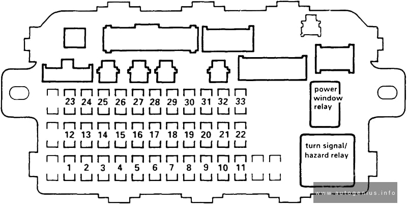
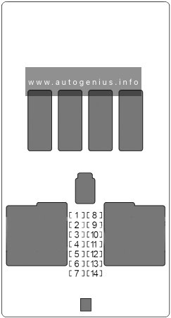
Passenger compartment
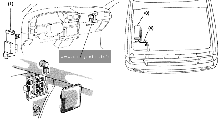
Fuse box location
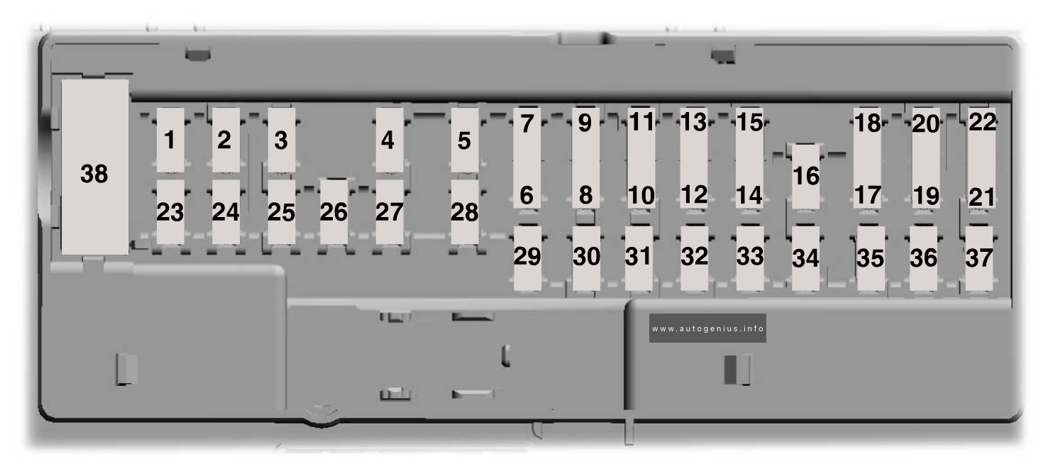
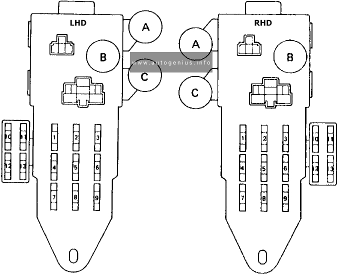
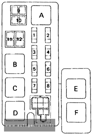
The fuse panel is in the passenger footwell. Remove the panel cover to access the fuses.
Fuse Box Diagrams
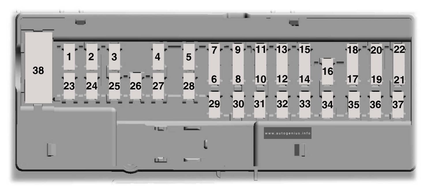
Assignment of the fuses in the passenger compartment fuse box
| № | Rating | Protected Component |
|---|---|---|
| 1 | — | Not used. |
| 2 | 10 A | Right-hand and left-hand front door lock switch. Telescopic mirror switch. Right-hand and left-hand front window switch (two window units). Right-hand and left-hand front window motor. Inverter. |
| 3 | 7.5 A | Power mirror switch. |
| 4 | 20 A | Ancillary translator module. |
| 5 | — | Not used. |
| 6 | — | Not used. |
| 7 | 10 A | Smart data link connector power. Air brake diagnostic connector. |
| 8 | — | Not used. |
| 9 | — | Not used. |
| 10 | — | Not used. |
| 11 | — | Not used. |
| 12 | 7.5 A | Smart data link connector. Enterprise wired-in-device (2021). |
| 13 | 7.5 A | Cluster. Steering column control module. |
| 14 | — | Not used. |
| 15 | 15 A | Climate control module. |
| 16 | — | Not used. |
| 17 | — | Not used. |
| 18 | 7.5 A | Yaw sensor. Electronic stability control and non-electric stability control. |
| 19 | 5 A | Telematics control unit module. |
| 20 | 5 A | Ignition switch. |
| 21 | — | Not used. |
| 22 | — | Not used. |
| 23 | 30 A | Left-hand front window motor. |
| 24 | — | Not used. |
| 25 | — | Not used. |
| 26 | 30 A | Right-hand front motor window. |
| 27 | — | Not used. |
| 28 | — | Not used. |
| 29 | 15 A | Relay folding mirror. |
| 30 | 5 A | Brake signal for air brake. Customer access stop lamp signal. Brake on-off isolation relay. Trailer tow stop lamp relay. |
| 31 | 10 A | Upfitter interface module. Remote radio frequency receiver. |
| 32 | 20 A | Radio. |
| 33 | — | Not used. |
| 34 | — | Not used. |
| 35 | 5 A | Tow haul switch. |
| 36 | 15 A | Lane departure warning camera. |
| 37 | — | Not used. |
| 38 | 30 A | Left-hand front power window switch (four window units). |
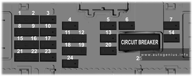
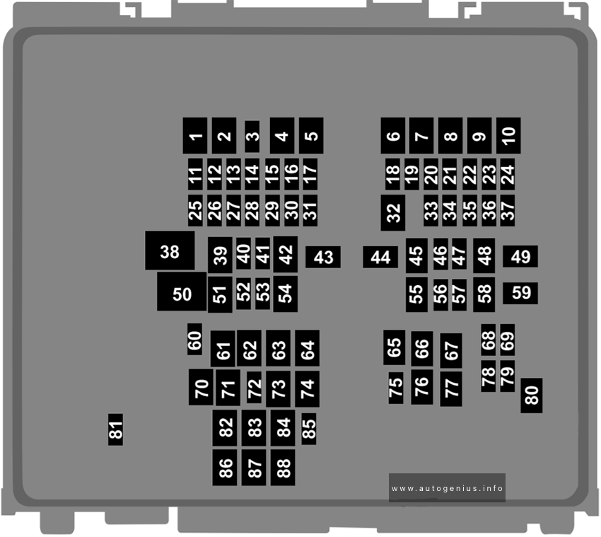
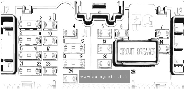
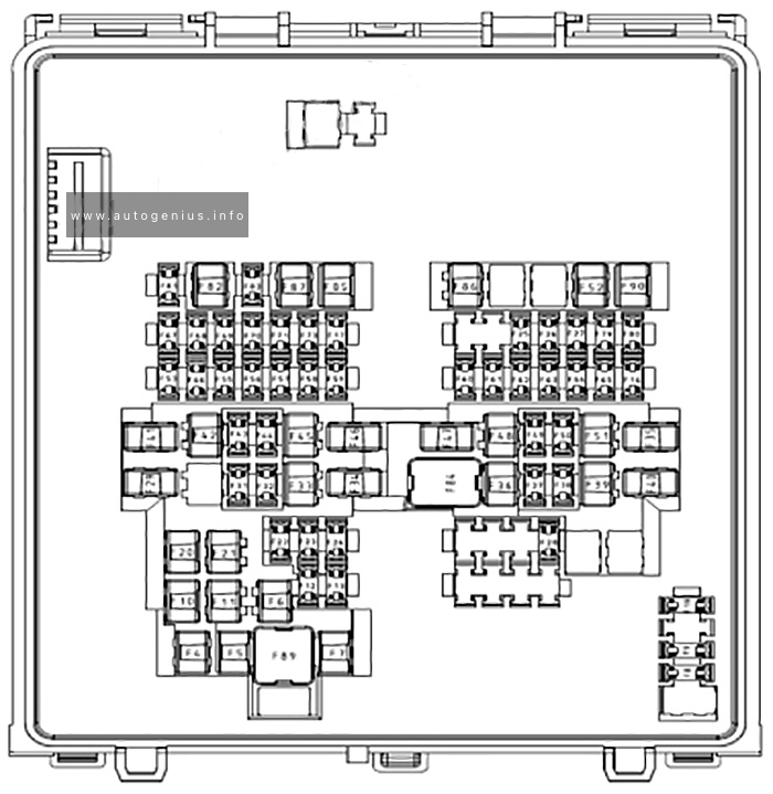
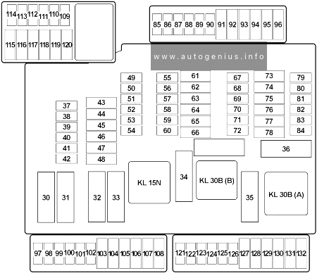
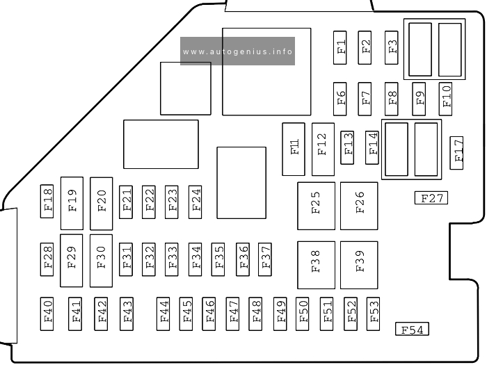
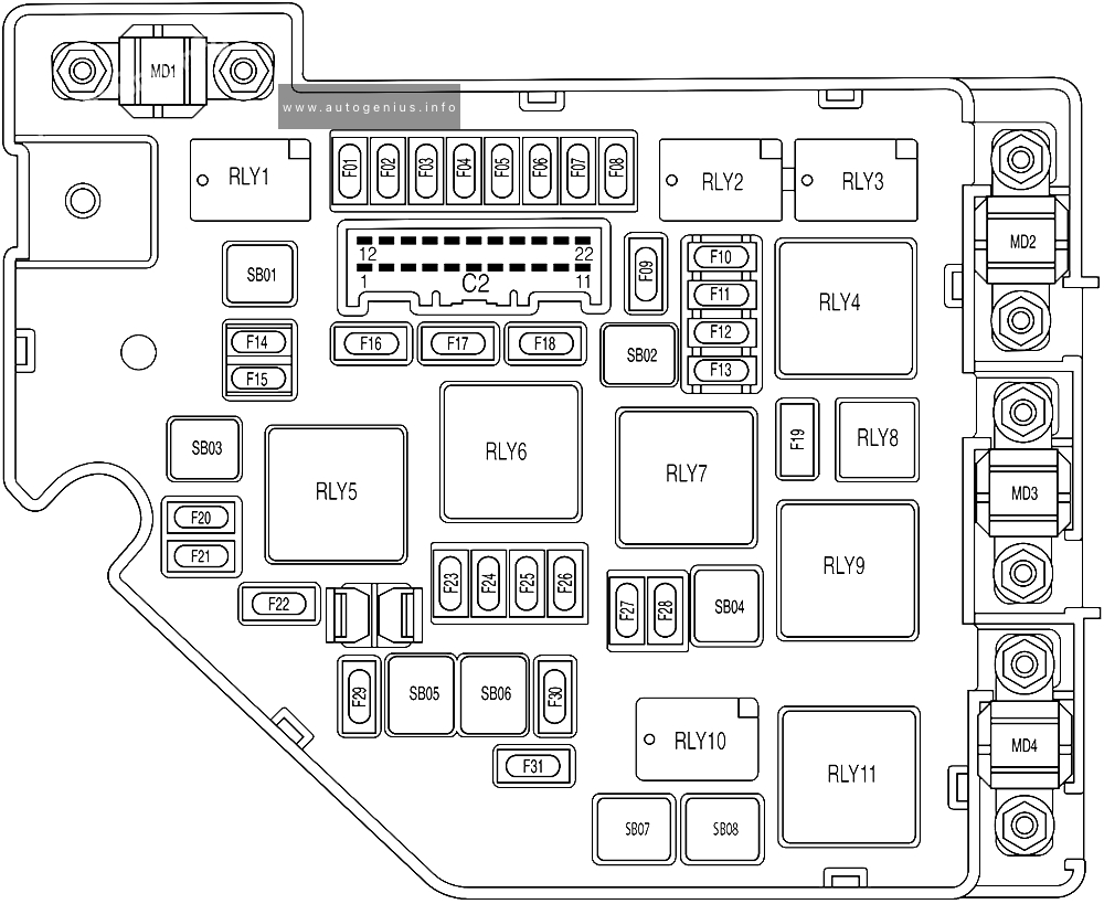
Engine Compartment Fuse Box
Fuse Box Diagrams
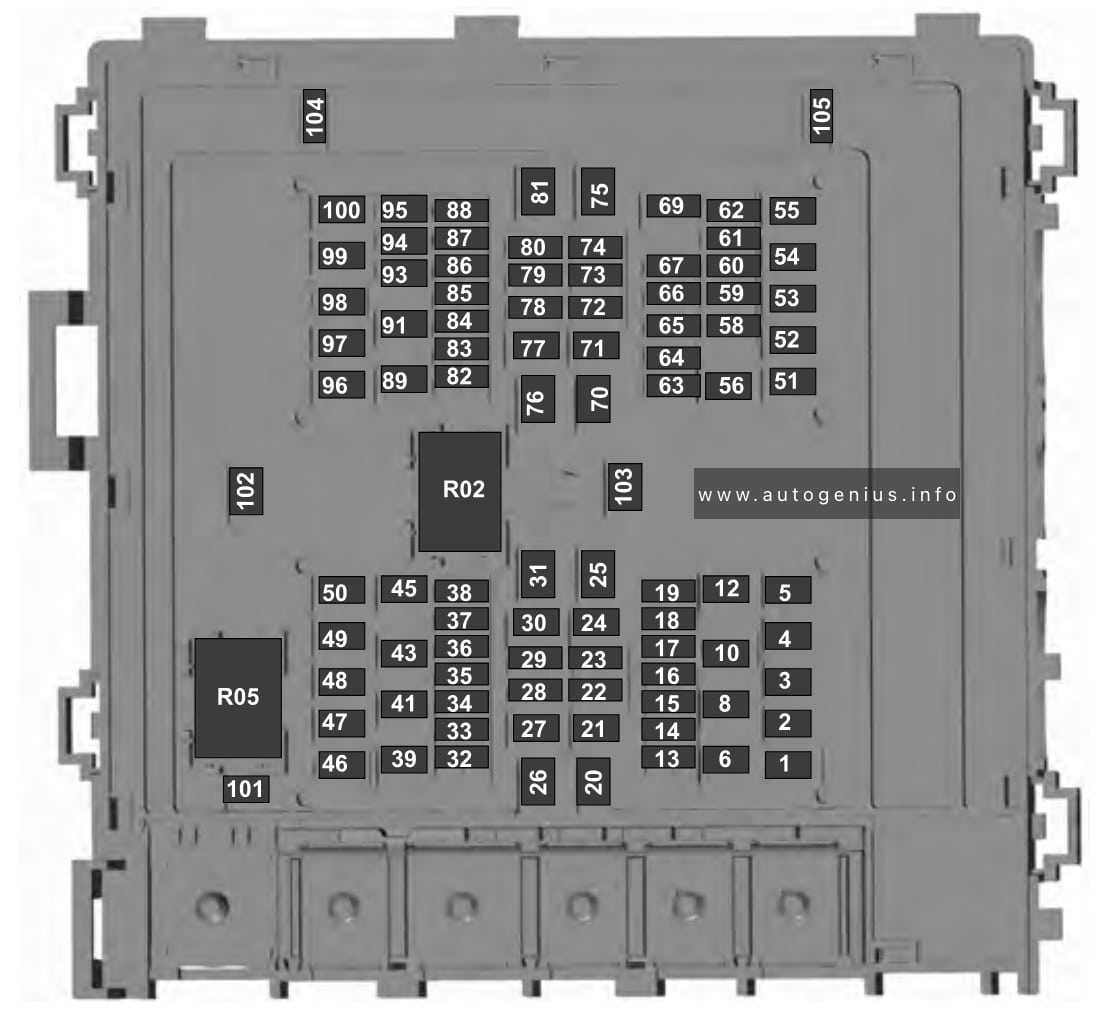
Assignment of the fuses in the engine compartment fuse box
| № | Rating | Protected Component |
|---|---|---|
| 1 | 20 A | Horn. |
| 2 | 40 A | Blower motor. Blower motor control. |
| 3 | 20 A | Upfit – frame. |
| 4 | 30 A | Starter motor. |
| 5 | — | Not used. |
| 6 | 20 A | Upfitter relay 4. |
| 8 | — | Not used. |
| 10 | — | Not used. |
| 12 | — | Not used. |
| 13 | 10 A | Run/start spare. |
| 14 | 10 A | Adaptive cruise control. |
| 15 | 10 A | Blower motor relay. |
| 16 | 20 A | Air dryer. |
| 17 | 10 A | Powertrain control module – ignition status run power. Glow plug control module – ignition status run power (diesel). |
| 18 | 10 A | Anti-lock brake system run/start. |
| 19 | 10 A | Transmission control module. Ignition status run power (diesel). |
| 20 | 30 A | Windshield wiper motor. |
| 21 | — | Not used. |
| 22 | — | Not used. |
| 23 | 10 A | Alternator 2 (dual alternator only). |
| 24 | 40 A | Body control module run power 2 bus. |
| 25 | 50 A | Body control module run power 1 bus. |
| 26 | — | Not used. |
| 27 | 20 A | Body builder battery feed. |
| 28 | — | Not used. |
| 29 | 10 A | Alternator 1 A-Line. |
| 30 | — | Not used. |
| 31 | 60 A | Hydromax pump. |
| 32 | 20 A | Powertrain control module. |
| 33 | 20 A | Canister vent solenoid (gas). Canister purge solenoid (gas). Variable cam timing actuator 11 (gas). Heated exhaust gas oxygen sensor (gas). Urea tank power (diesel). Exhaust gas recirculation cool bypass valve (diesel). |
| 34 | 10 A | A/C clutch relay. Customer access vehicle power 3 feed. Variable oil pump (diesel). Cooling fan (diesel). Fan clutch (gas). Exhaust brake switch (2022). |
| 35 | 20 A | Coil on plug (gas). Urea tank (diesel). Glow plug controller (diesel). Nitrogen oxide sensor control module (diesel). Particulate matter sensor (diesel). |
| 36 | 10 A | Fuel volume control value (diesel). Fuel pressure regulator (diesel). |
| 37 | — | Not used. |
| 38 | — | Not used. |
| 39 | — | Not used. |
| 41 | 30 A | Trailer brake control module. |
| 43 | 30 A | Upfitter spare. |
| 45 | — | Not used. |
| 46 | 10 A | A/C clutch solenoid. |
| 47 | 40 A | Upfitter relay 1. |
| 48 | 20 A | Upfitter run and accessory feed. |
| 49 | 30 A | Pump electronics module (gas). Fuel pump (diesel). |
| 50 | 15 A | Injector power (gas). |
| 51 | 20 A | Power point #1. |
| 52 | — | Not used. |
| 53 | 30 A | Trailer tow park lamp. |
| 54 | — | Not used. |
| 55 | 20 A | Upfitter relay 3. |
| 56 | — | Not used. |
| 58 | 5 A | USB power. |
| 59 | 10 A | U-Haul park lamps. |
| 60 | 10 A | Dual fuel tank selector switch (diesel). |
| 61 | — | Not used. |
| 62 | — | Not used. |
| 63 | 20 A | Driver seat compressor. |
| 64 | 20 A | Passenger seat compressor. |
| 65 | 10 A | Upfit – run activate feed. |
| 66 | 10 A | Four pack solenoid differential lock. |
| 67 | 10 A | Hydromax relay power. |
| 69 | — | Not used. |
| 70 | 40 A | Inverter. |
| 71 | 30 A | Anti-lock brake system valves. |
| 72 | 10 A | Brake on-off switch (hydraulic brakes). Stop lamp air pressure switch 1 and 2 (air brakes). |
| 73 | — | Not used. |
| 74 | 15 A | Heated mirror. |
| 75 | — | Not used. |
| 76 | 60 A | Body control module battery feed. |
| 77 | 30 A | Body control module voltage quality monitor power feed. |
| 78 | 10 A | Transmission module (diesel). |
| 79 | 5 A | Hydromax pump monitor. |
| 80 | 10 A | Trailer tow backup signal. |
| 81 | — | Not used. |
| 82 | 5 A | Upfitter switch (factory location for ignition power). |
| 83 | 5 A | Upfitter switch (optional location for power at all times). |
| 84 | — | Not used. |
| 85 | — | Not used. |
| 86 | — | Not used. |
| 87 | — | Not used. |
| 88 | 10 A | Cargo lamps. |
| 89 | — | Not used. |
| 91 | 40 | Upfitter – B-pillar. |
| 93 | — | Not used. |
| 94 | — | Not used. |
| 95 | 20 A | Stop lamps. Trailer tow stop lamps. |
| 96 | — | Not used. |
| 97 | — | Not used. |
| 98 | 30 A | Trailer tow battery charge. |
| 99 | 40 A | Upfitter relay 2. |
| 100 | 25 A | Glow plug controller (diesel). |
| 101 | — | Not used. |
| 102 | — | Not used. |
| 103 | — | Not used. |
| 104 | — | Not used. |
| 105 | 15 A | Trailer tow stop and turn relay. |
WARNING: Terminal and harness assignments for individual connectors will vary depending on vehicle equipment level, model, and market.