Iveco Daily (III; 2000 – 2006) – fuse and relay box diagram
Year of production: 2000, 2001, 2002, 2003, 2004, 2005, 2006
This article covers the second-generation Iveco Daily (III), produced from 2000 to 2006. It includes fuse box diagrams for the 2000, 2001, 2002, 2003, 2004, 2005 and 2006 models, provides details on the location of the fuse panels inside the vehicle, and explains the function and layout of each fuse.
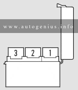
Passenger compartment
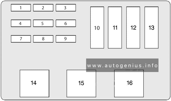
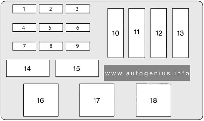
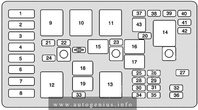
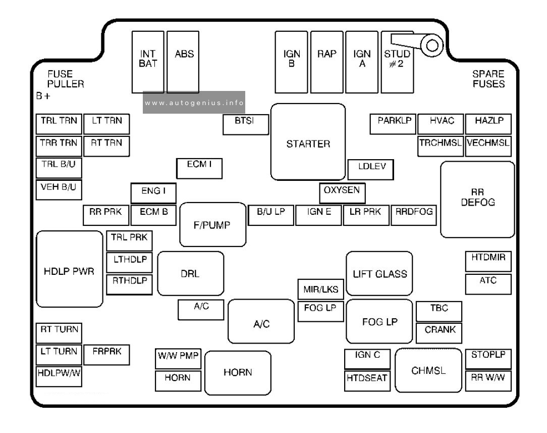
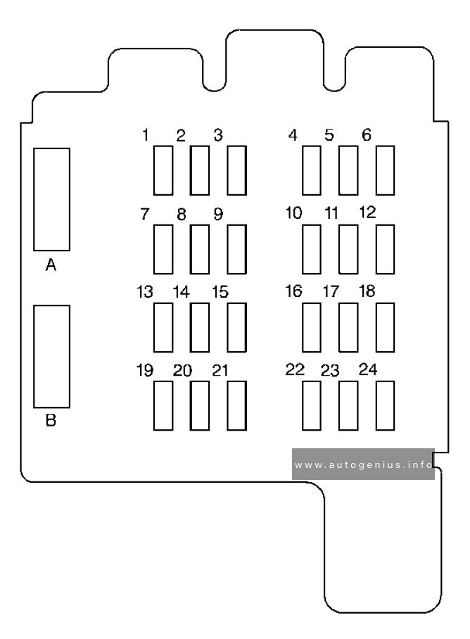
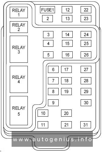
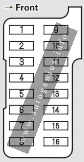
Fuse box diagram
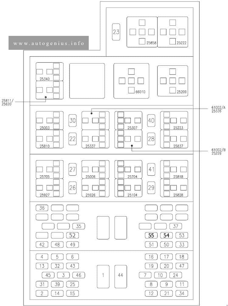
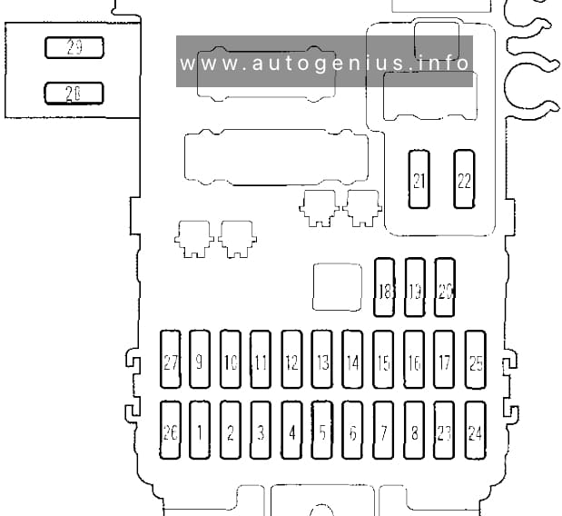
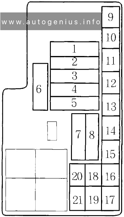
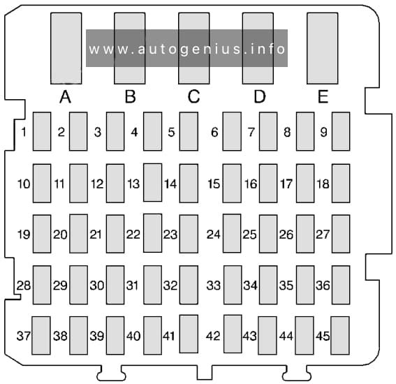
Assignment of the fuses in the passenger compartment
| No | Function | A |
| 1 | ID/TCA (.11): Thermal starter | 40 |
| 1 | UNIJET (.13-.15): Thermal starter | 80 |
| 1 | UNIJET F1A (.10-.12): Thermal starter, additional heater | 30 |
| 2 | Immobilizer/Warming/EDC | 5 |
| 3 | DDS device | 5 |
| 4 | Instrument cluster (+30) | 5 |
| 5 | Instrument cluster (+15) | 5 |
| 6 | Stalk unit (rear fog guard, flasher) | 5 |
| 7 | Stalk unit (low beams) | 10 |
| 8 | Stalk unit (high beams) | 15 |
| 9 | Stalk unit (side lights) | 15 |
| 10 | Windscreen wiper | 15 |
| 11 | Stalk unit (direction indicators/hazard warning lights) | 15 |
| 12 | Stalk unit (horns) | 15 |
| 13 | Reversing light | 5 |
| 14 | Side light, clearance, no. plate light | 5 |
| 15 | Side light cluster lighting | 5 |
| 16 | Left low beam headlamp | 10 |
| 17 | Right low beam headlamp | 10 |
| 18 | Left high beam headlamp | 10 |
| 19 | Right high beam headlamp/headlamp aming | 10 |
| 20 | Interior lighting/radio/cigar lighter | 10 |
| 20 | UNIJET F1A (.10-.12): Interior lighting/radio | 10 |
| 21 | Electric windscreen defrosting unit | 30 |
| 21 | UNIJET F1A (.10-.12): Cigar lighter | 15 |
| 22 | Heated fuel filter | 15 |
| 23 | EDC electronic control unit | 25 |
| 24 | EDC | 10 |
| 25 | Stop lights | 5 |
| 26 | 13-pin current socket | 15 |
| 27 | 13-pin current socket | 15 |
| 28 | 13-pin current socket | 10 |
| 29 | 38-pin diagnostic connector | 5 |
| 30 | Fog lamps | 10 |
| 31 | Climate control, additional heater, engine cooling | 5 |
| 31 | UNIJET F1A (.10-.12): Compressor, timer, engine fan | 10 |
| 32 | Climate control | 5 |
| 33 | Additional heater | 20 |
| 34 | Headlamp washer | 20 |
| 35 | Rear differential lock | 5 |
| 36 | ABS, EBD, ABD failure warning light | 5 |
| 37 | ABS | 5 |
| 39 | Heated mirrors | 10 |
| 39 | UNIJET F1A (.10-.12): Heated mirrors, heated rear-screen, heated windscreen | 10 |
| 40 | Power windows | 30 |
| 40 | UNIJET F1A (.10-.12): Power windows (left) | 20 |
| 41 | Heated rear-screen, heated windscreen | 10/ 20 |
| 42 | Self-levelling suspensions (Wabco) | 5 |
| 43 | Air bag failure warning light | 5 |
| 44 | Self-levelling suspensions (Wabco) | 40 |
| 45 | Air-bag | 5 |
| 46 | Solenoid valve for thermal starter | 5 |
| 46 | UNIJET F1A (.10-.12): Power windows (right) | 20 |
| 47 | Electric fuel pump | 10 |
| 48 | Door locking/alarm | 30 |
| 49 | Door locking/alarm | 5 |
| 50 | Rear differential lock | 30 |
| 51 | Total power takeoff | 10 |
| 52 | Front differential lock (4×4) | 30 |
| 53 | Self-levelling suspensions Techniek) | 30 |
| 54 | Electric hatch (van and 6+1) | 15 |
| 55 | Rototranslating door | 15 |
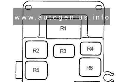
| Code | Relays | |
| 25035 | Switching on external lights | |
| 25003 | Switching on fog lamps | |
| 25006 | Switching on stop lights | |
| 25704 | Total power takeoff engagement control | |
| 25104 | Switching off Retarder with ABS on | |
| 25209 | Loads cut-off during starting | |
| 25222 | Thermal starter engagement enable | |
| 25223 | Thermal starter fan control | |
| 25307 | Climate control compressor engagement | |
| 25336 | Engine cooling | |
| 25337 | Climate control compressor disengagement | |
| 25340 | Compressor on signal | |
| 25620 | Fuel filter clogged signal | |
| 25705 | Diagnostics enable | |
| 25810 | Heated fuel filter circuit control | |
| 25811 | Advance variator control (KSB) | |
| 25818 | Heated windscreen switching on | |
| 25837 | Electric fuel pump switching on | |
| 25858 | EDC switching on | |
| 25926 | Suspension raising enable | |
| 25927 | Suspension lowering enable | |
| 25928 | Rear-screen heating switching on | |
| 61002A | Anti-retum from Trinary | |
| 61002В | Anti-retum from TGC (bus) | |
| 66010 | Timer for headlamp washer | |
WARNING: Terminal and harness assignments for individual connectors will vary depending on vehicle equipment level, model, and market.