Volkswagen EOS (2009 – 2011) – fuse and relay box diagram
Year of production: 2009, 2010, 2011, 2012
The Volkswagen Eos coupé-cabriolet was manufactured from 2006 to 2016. This article provides fuse box diagrams for the Volkswagen Eos models from 2009 to 2011. You will also find details on the location of the fuse panels inside the vehicle and information about the fuse and relay assignments (fuse layout).
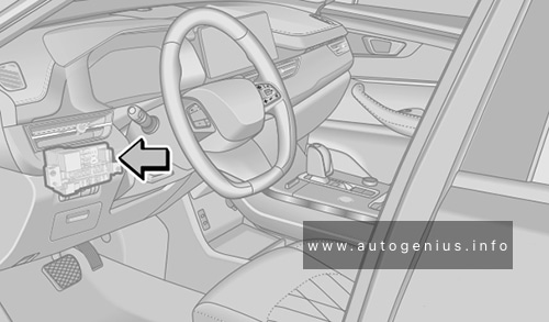
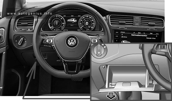
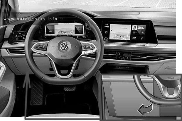
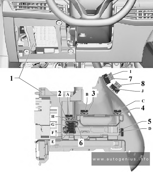
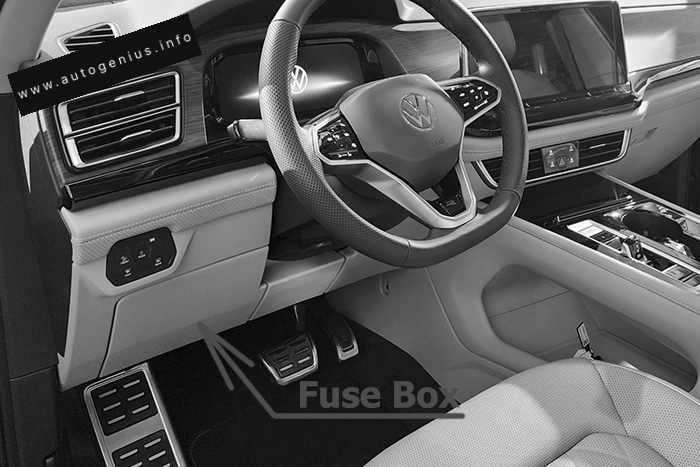
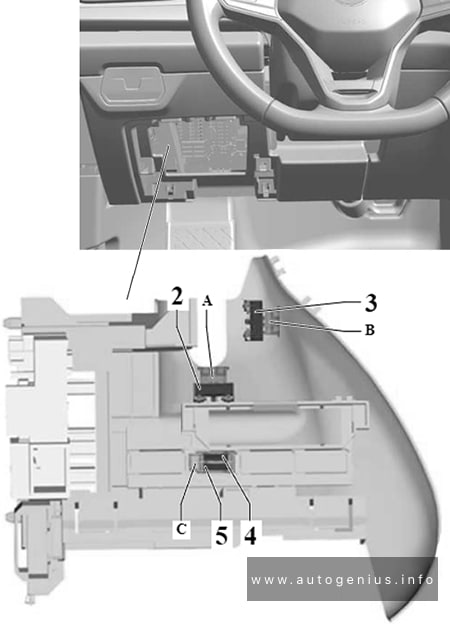
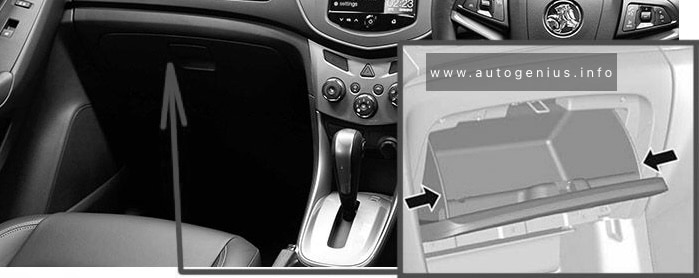
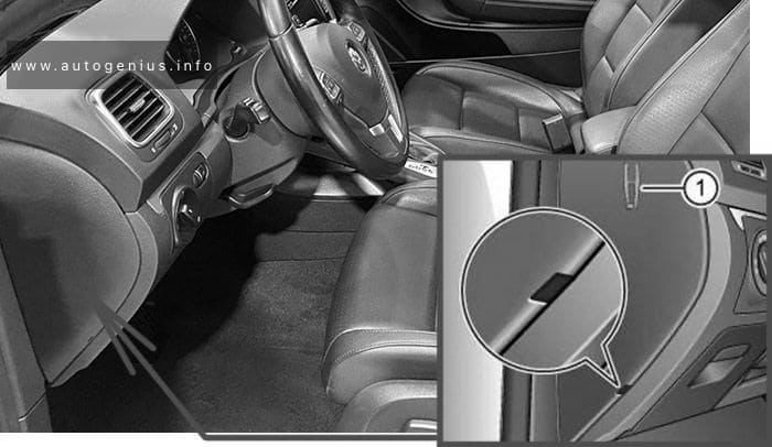
Instrument Panel Fuse Box (Fuse Panel -SC-)
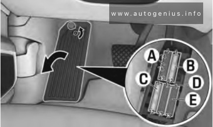
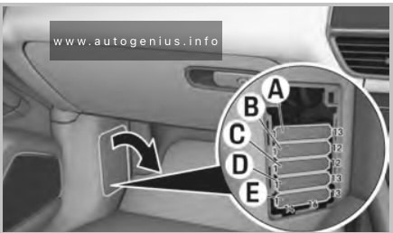
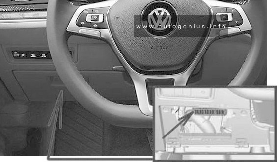
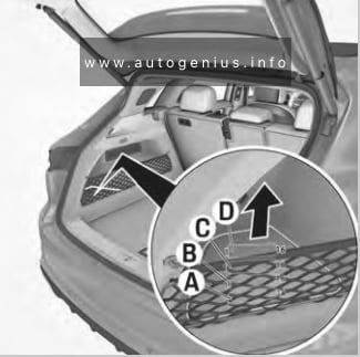
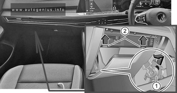
Fuse Box Location
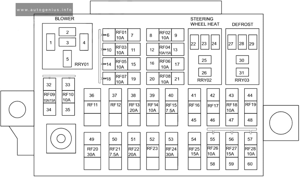
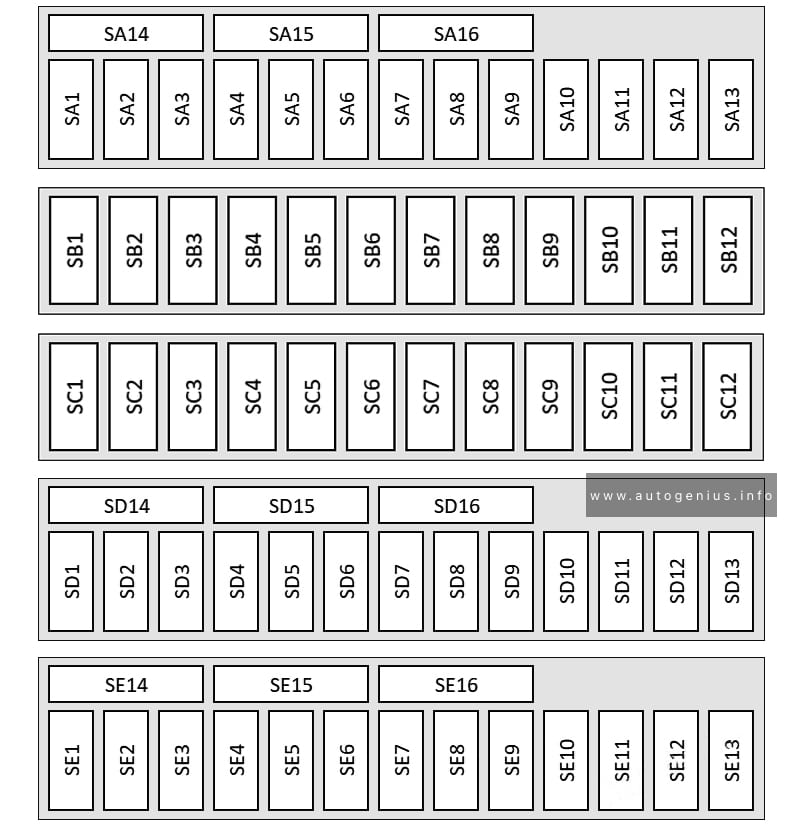
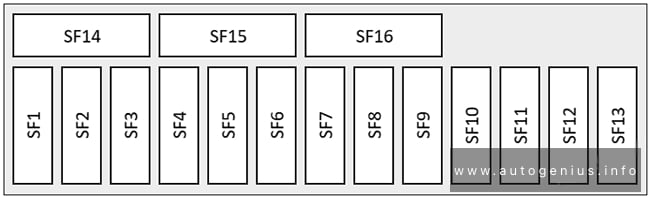
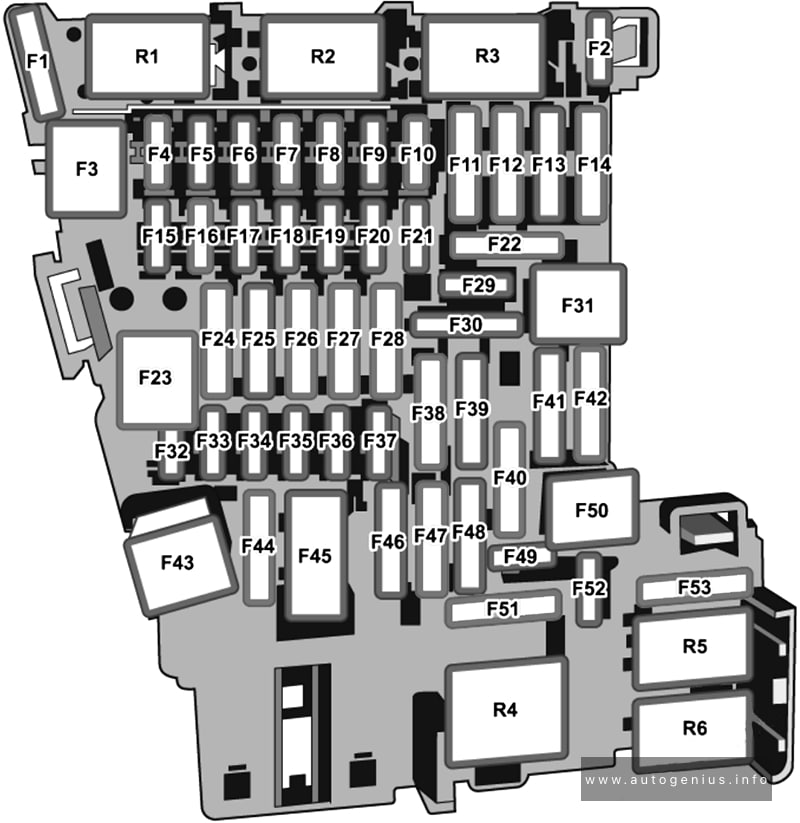
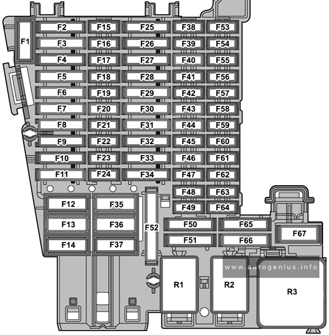
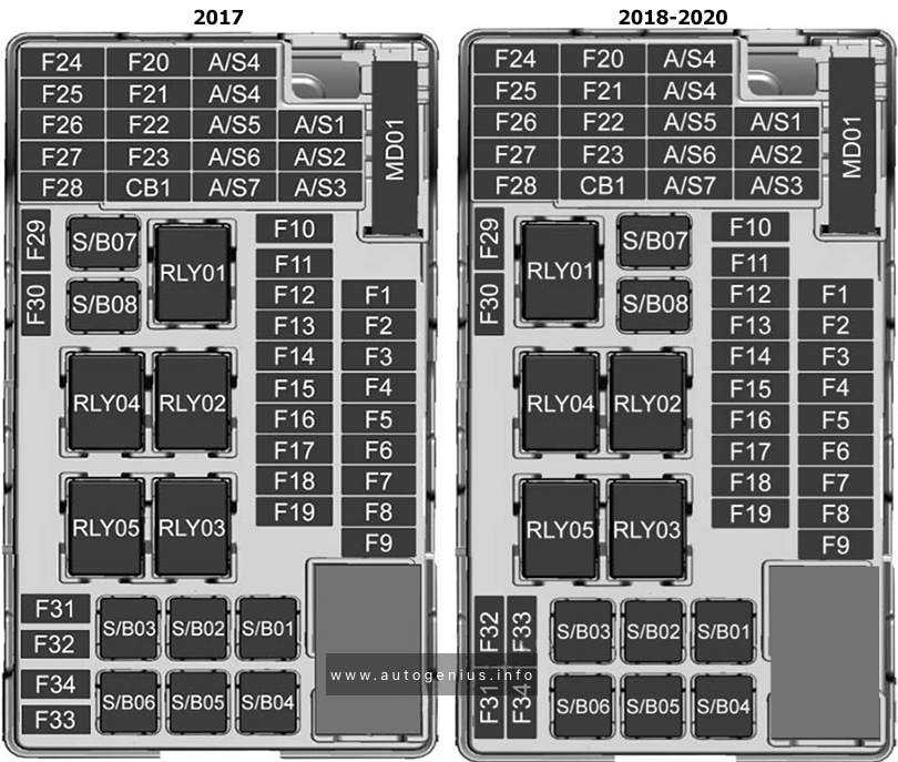
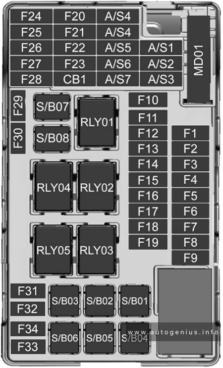
Fuse Box Diagram
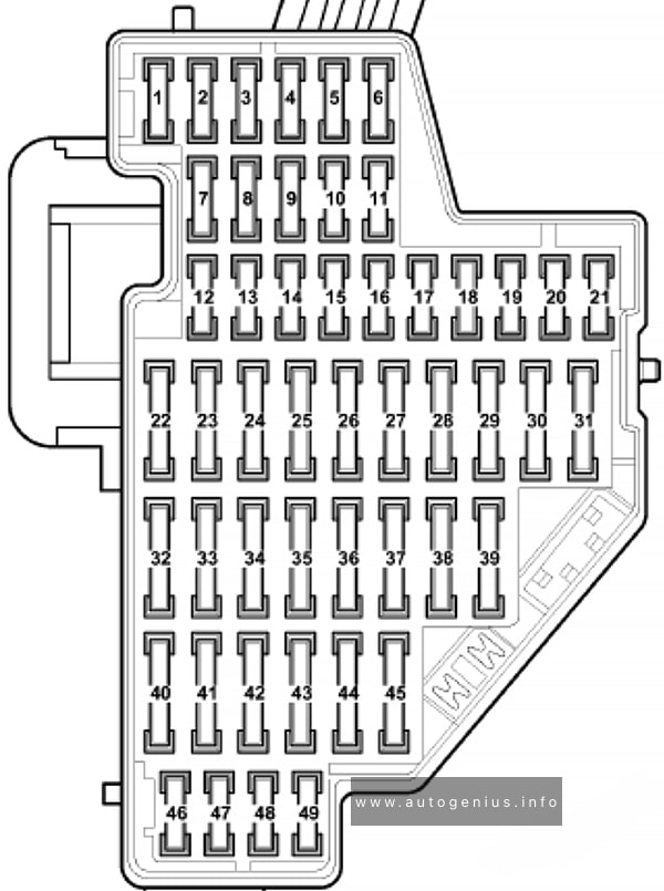
Assignment of the fuses in the instrument panel
| № | Amps | Function/Component |
|---|---|---|
| F1 | 10A | 16-Pin Connector – Data Link Connector Instrument Panel Illumination Dimmer Switch Mass Air Flow (MAF) Sensor Auxiliary Heater Operation Relay Parking Aid Control Module Headlamp Range/Cornering Lamp Control Module Positive Crankcase Ventilation (PCV) Heating Element Left Headlamp Beam Adjustment Motor Right Headlamp Beam Adjustment Motor |
| F2 | 5A | Light Switch Brake Light Switch ABS Control Module Electronic Damping Control Module Motronic Engine Control Module (ECM) Power Supply Relay Instrument Cluster Control Module Towing Recognition Control Module Power Steering Control Module Data Bus On Board Diagnostic Interface Fuel Pump (FP) Control Module Selector Lever Sensors Control Module Engine Control Module (ECM) Direct Shift Gearbox (DSG) Mechatronic |
| F3 | 10A | Airbag Control Module |
| F4 | 5A | Tire Pressure Monitoring Button High Pressure Sensor Oil Level Thermal Sensor Driver’s Heated Seat Control Module Front Passenger’s Heated Seat Control Module Climatronic Control Module Vehicle Electrical System Control Module 2 Automatic Day/Night Interior Mirror Left Washer Nozzle Heater Right Washer Nozzle Heater |
| F5 | – | Not used |
| F6 | – | Not used |
| F7 | – | Not used |
| F8 | – | Not used |
| F9 | – | Not used |
| F10 | – | Not used |
| F11 | – | Not used |
| F12 | 10A | Driver’s Door Control Module Front Passenger’s Door Control Module |
| F13 | 10A | Light Switch 16-Pin Connector – Data Link Connector Rain/Light Recognition Sensor |
| F14 | 10A | Climatronic Control Module A/C Control Module Selector Lever Sensors Control Module Auxiliary Engine Coolant Heating RF Receiver |
| F15 | 7.5A | Vehicle Electrical System Control Module |
| F16 | – | Not used |
| F17 | 5A | Alarm Horn Radar Interior Monitoring Control Module 1 Radar Interior Monitoring Control Module 2 Vehicle Inclination Sensor – Alarm Horn Relay (Only applicable to US/CDN) |
| F18 | – | Not used |
| F19 | 7.5A | Door Closing Assist Control Module |
| F20 | – | Not used |
| F21 | – | Not used |
| F22 | 40A | Fresh Air Blower Control Module |
| F23 | 30A | Driver’s Door Control Module Front Passenger’s Door Control Module |
| F24 | – | Not used |
| F25 | 25A | Fresh Air Blower Relay |
| F26 | – | Not used |
| F27 | 15A | Fuel Pump (FP) Control Module Fuel Pump (FP) Relay Auxiliary Fuel Pump Relay |
| F28 | – | Not used |
| F29 | – | Not used |
| F30 | – | Not used |
| F31 | – | Not used |
| F32 | 30A | Left Rear Door Control Module Right Rear Door Control Module |
| F33 | – | Not used |
| F34 | 15A | Driver’s Seat Lumbar Support Adjustment Switch Front Passenger’s Seat Lumbar Support Adjustment Switch |
| F35 | 10A | Electronic Damping Control Module |
| F36 | 20A | Headlamp Washer Relay Headlamp Washer Pump |
| F37 | 30A | Front Heated Seats Control Module |
| F38 | 20A | Comfort System Central Control Module |
| F39 | – | Not used |
| F40 | 40A | A/C Control Module Auxiliary Heater Operation Relay |
| F41 | 15A | Windshield Washer Pump |
| F42 | 15A | Blocking Diode 2 Cigarette Lighter 12V Socket |
| F43 | 15A | Towing Recognition Control Module |
| F44 | 20A | Towing Recognition Control Module |
| F45 | 15A | Towing Recognition Control Module |
| F46 | – | Not used |
| F47 | – | Not used |
| F48 | – | Not used |
| F49 | – | Not used |
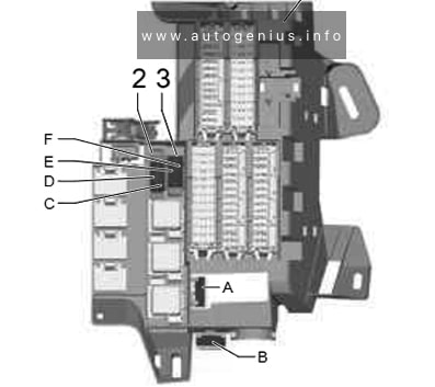
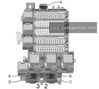
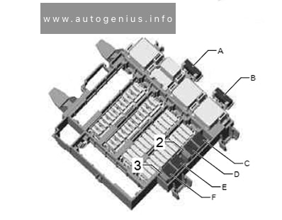
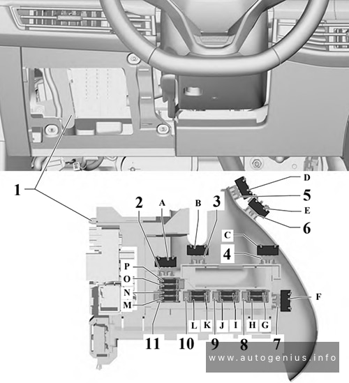
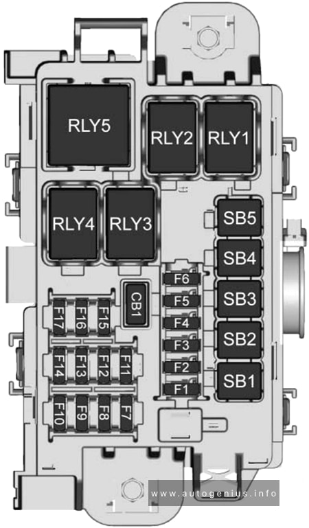
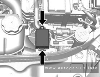
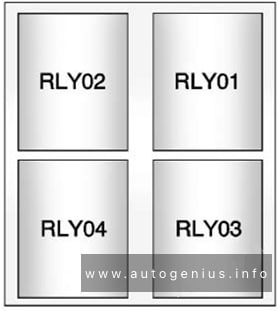
Relays under instrument panel
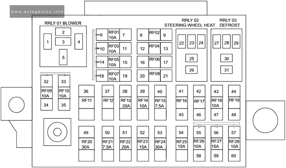
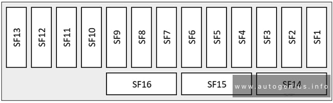
Fuse Box Diagram
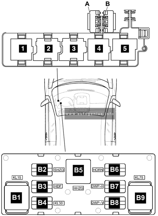
Assignment of the raleys in the instrument panel
| № | Amps | Function |
|---|---|---|
| B1 | Power Supply Relay 2 (terminal 15) | |
| B2 | – | |
| B3 | – | |
| B4 | Power Supply Relay 2 (terminal 30) | |
| B5 | Rear Window Defogger Relay | |
| B6 | Dual Horn Relay | |
| B7 | Dual Washer Pump Relay 1 | |
| B8 | Dual Washer Pump Relay 2 | |
| B9 | Load Reduction Relay | |
| A | 20A CB | From May 2006 to May 2008: Convertible Top Motor Circuit Breaker From May 2008: Sunroof Circuit Breaker |
| B | 20A CB | Driver’s Power Seat Adjustment Circuit Breaker 1 |
| 1 | Auxiliary Heater Operation Relay / Alarm Horn Relay (only applicable to US/CDN, from November 2006) | |
| 2 | Fresh Air Blower Relay (only additional water heater) | |
| 3 | Power Supply Relay (terminal 50) / Headlamp Washer Relay | |
| 4 | Headlamp Washer Relay / Fuel Pump (FP) Relay | |
| 5 | Fuel Pump (FP) Relay / Power Supply Relay (terminal 50) |
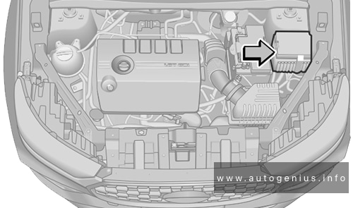
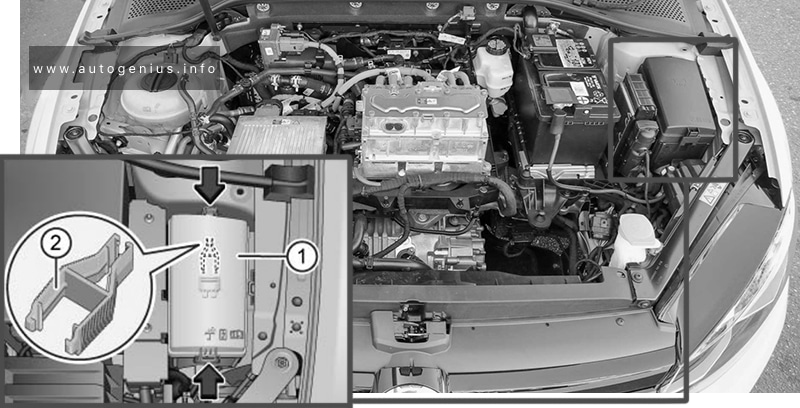
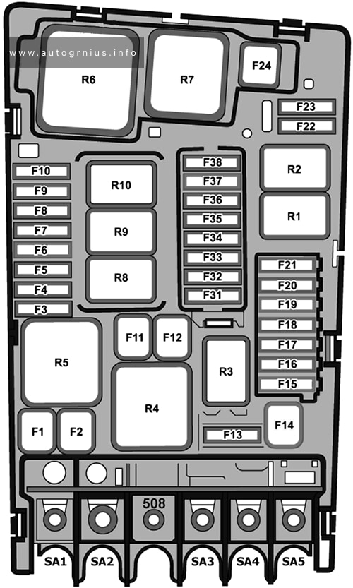
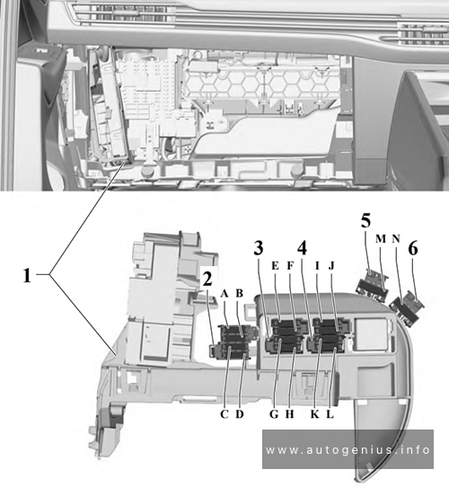
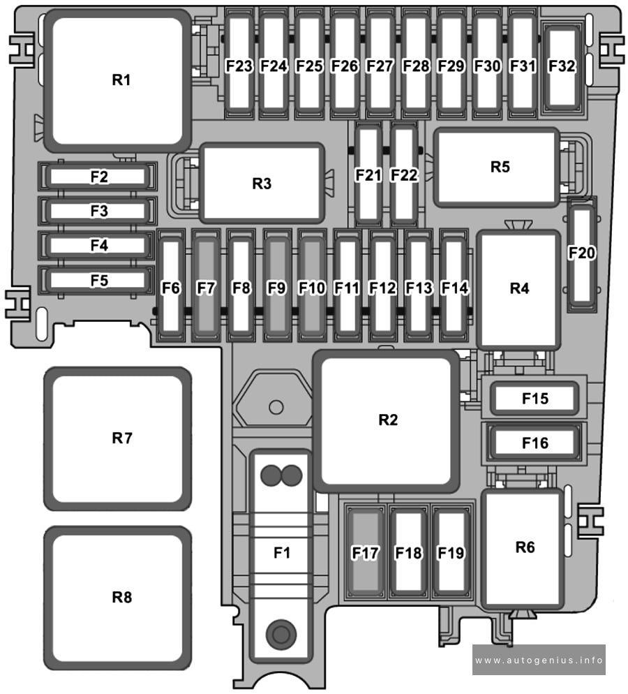
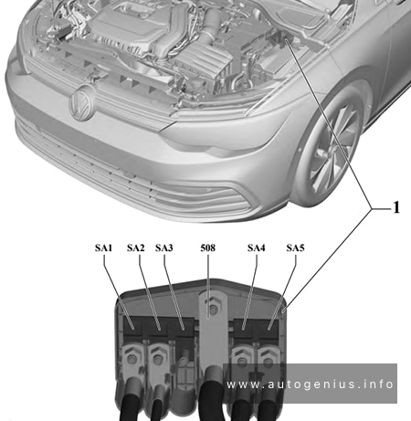
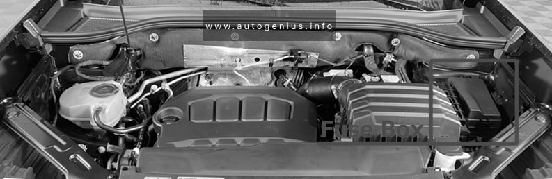
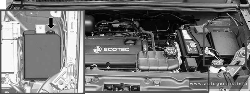
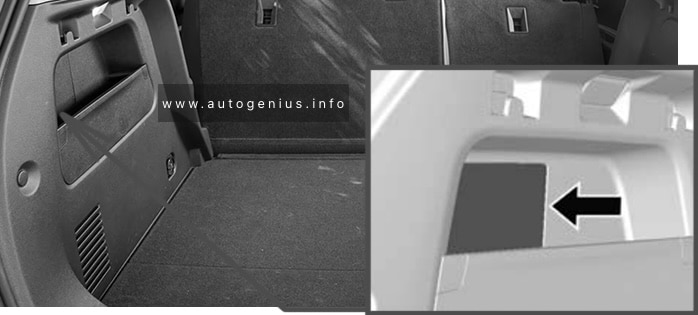
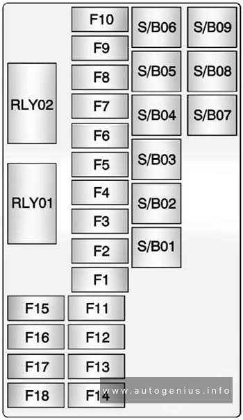
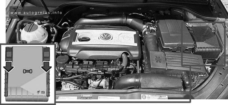
Engine Compartment Fuse Boxes (Fuse Panels -SA-&-SB-)
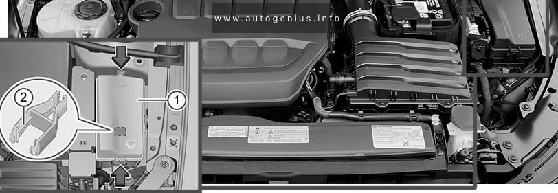
Fuse Box Location
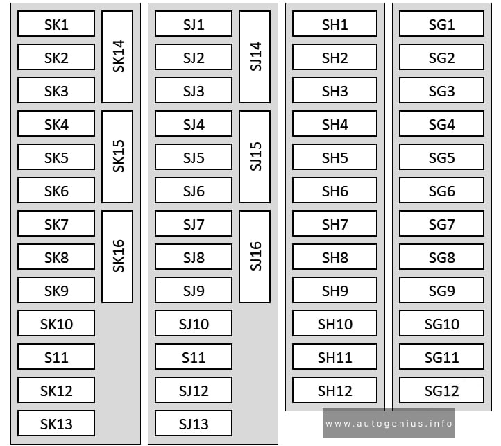
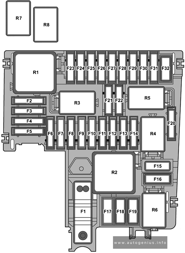
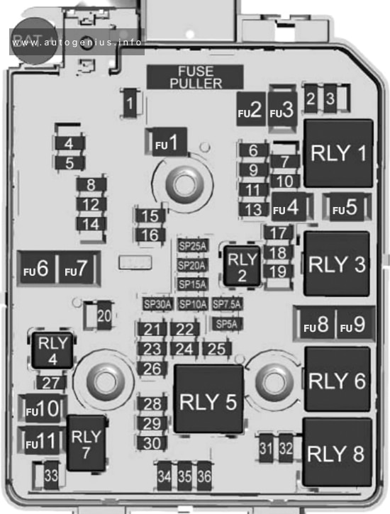
Fuse Box Diagram (Version 1, Low)
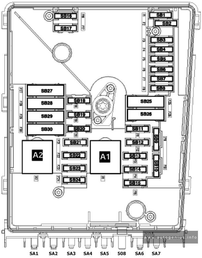
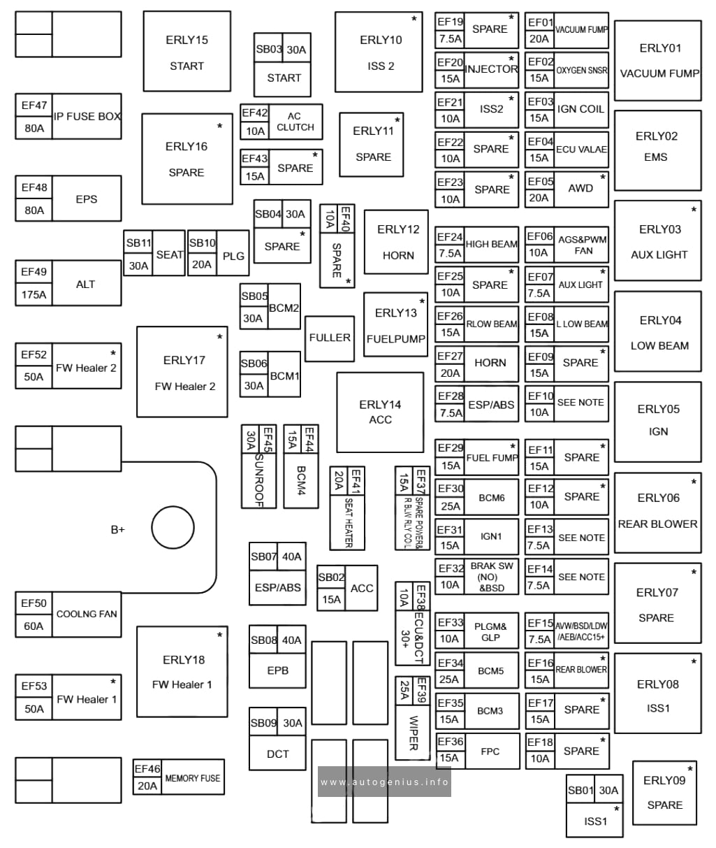
Assignment of the fuses in the engine compartment (Version 1, Low)
| № | Amps | Function/Component |
|---|---|---|
| F1 | 20A | From January 2006 to May 2006: Comfort System Central Control Module |
| F2 | 5A | From January 2006 to May 2008: Steering Column Electronic Systems Control Module |
| F3 | 5A | Vehicle Electrical System Control Module |
| F4 | 20A/30A | ABS Control Module |
| F5 | 15A | Direct Shift Gearbox (DSG) Mechatronic |
| F6 | 5A | Instrument Cluster Control Module Steering Column Electronic Systems Control Module (from May 2008) |
| F7 | 15A/40A | From January 2006 to May 2006: Special Purpose Vehicle Control Module
From May 2008: Power Supply Relay 2 (terminal 15) |
| F8 | 15A | Radio/Navigation Display Control Module TV/Radio/Navigation Display/Control Module Radio Digital Satellite Radio Tuner |
| F9 | 5A | Telephone Transceiver |
| F10 | 5A/10A | Motronic Engine Control Module (ECM) Power Supply Relay (only models with gasoline engine, not for engine code BLF) Engine Control Module (ECM) Transmission Control Module (TCM) (From January 2006 to May 2006: ) |
| F11 | 20A | Auxiliary Heater Control Module |
| F12 | 5A | Data Bus On Board Diagnostic Interface |
| F13 | 30A/25A/15A | Engine Control Module (ECM) |
| F14 | 20A | Ignition Coil Ignition Coil 1-4 with Power Output Stage |
| F15 | 10A/5A | Heated Oxygen Sensor (HO2S) (BVY) Oxygen Sensor (O2S) Behind Three Way Catalytic Converter (TWC) (BVY) Oxygen Sensor (O2S) 2 Behind Three Way Catalytic Converter (TWC) (BVY) Oxygen Sensor (O2S) 3 Behind Three Way Catalytic Converter (TWC) (BVY) Fuel Pump (FP) Relay Automatic Glow Time Control Module |
| F16 | 30A | ABS Control Module |
| F17 | 15A | High Tone Horn Low Tone Horn |
| F18 | 30A | Special Purpose Vehicle Control Module Amplifier |
| F19 | 30A | Wiper Motor Control Module Windshield Wiper Motor |
| F20 | – | Not used |
| F21 | 10A/15A/25A | Oxygen Sensor (O2S) Heater |
| F22 | 5A | Clutch Position Sensor |
| F23 | 5A/10A/15A | Secondary Air Injection (AIR) Pump Relay EGR Vacuum Regulator Solenoid Valve Wastegate Bypass Regulator Valve Exhaust Gas Recirculation (EGR) Cooler Switch-Over Valve Exhaust Gas Recirculation (EGR) Cooler Switch-Over Valve 2 Fuel Pressure Regulator Valve |
| F24 | 10A | From January 2006 to May 2008: Map Controlled Engine Cooling Thermostat Coolant Fan Control (FC) Control Module EGR Vacuum Regulator Solenoid Valve Evaporative Emission (EVAP) Canister Purge Regulator Valve 1 Intake Manifold Tuning (IMT) Valve Camshaft Adjustment Valve 1 Intake Manifold Runner Control (IMRC) Valve Ignition Coil Power Output StageFrom May 2008: Coolant Fan Control (FC) Control Module |
| F25 | 40A | From January 2006 to May 2008: Vehicle Electrical System Control Module (T11b/1) Terminal 30 – R From May 2008: ABS Control Module |
| F26 | 40A | Vehicle Electrical System Control Module (T11 c/1) Terminal 30 – L |
| F27 | 40A/50A | Automatic Glow Time Control Module |
| F28 | 40A | From January 2006 to May 2008: Power Supply Relay 2 (terminal 15) From May 2008: Convertible Top Control Module |
| F29 | 50A | From May 2006: Convertible Top Control Module (From May 2006 to May 2008) Left Rear Door Control Module Right Rear Door Control Module |
| F30 | 50A | Load Reduction Relay Fuse 7 (on fuse panel C) Fuse 8 (on fuse panel C) Fuse 28 (on fuse panel C) Fuse 35 (on fuse panel C) |
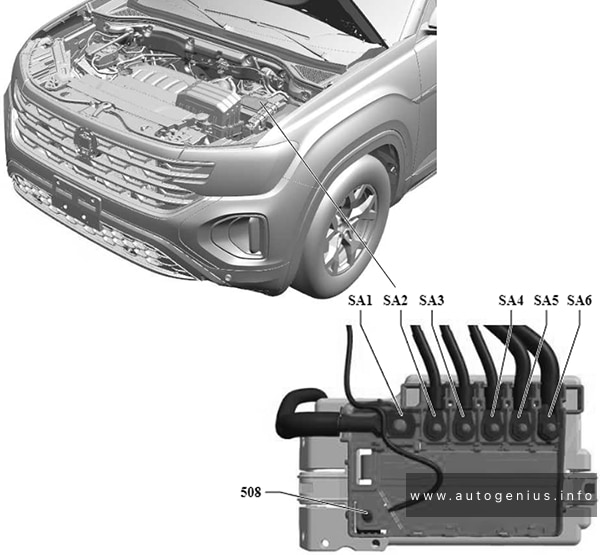
| SA1 | 150A/200A | Generator (GEN) (90A/120A) Generator (GEN) (140A) |
| SA2 | 80A | Power Steering Control Module Electro-mechanical Power Steering Motor |
| SA3 | 50A/80A | Coolant Fan Control (FC) Control Module Coolant Fan Coolant Fan 2 |
| SA4 | 40A | Special equipment |
| SA5 | 80A/100A | Fuse 43 (on fuse panel C) Fuse 45 (on fuse panel C) Fuse 28 (on fuse panel C) Fuse 22 (on fuse panel C) Fuse 18 (on fuse panel C) Fuse 19 (on fuse panel C) Fuse 12 (on fuse panel C) Fuse Panel C |
| 508 | – | Terminal 30 feed |
| SA6 | 80A/100A | Auxiliary Air Heater Control Module Auxiliary Air Heater Heating Element |
| SA7 | 50A/40A/30A | From January 2006 to May 2006: Trailer Handicapped equipmentFrom May 2006 to May 2008: Convertible Top Control Module Convertible Top Hydraulic Pump |
| A1 | Motronic Engine Control Module (ECM) Power Supply Relay | |
| A2 | Secondary Air Injection (AIR) Pump Relay Connection bridge, Automatic Glow Time Control Module, Glow Plug 1-4 |
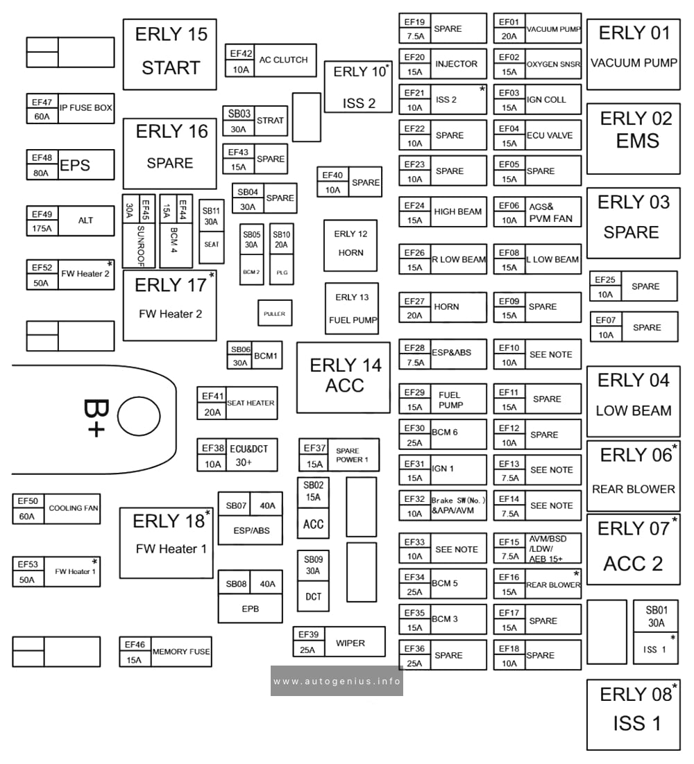
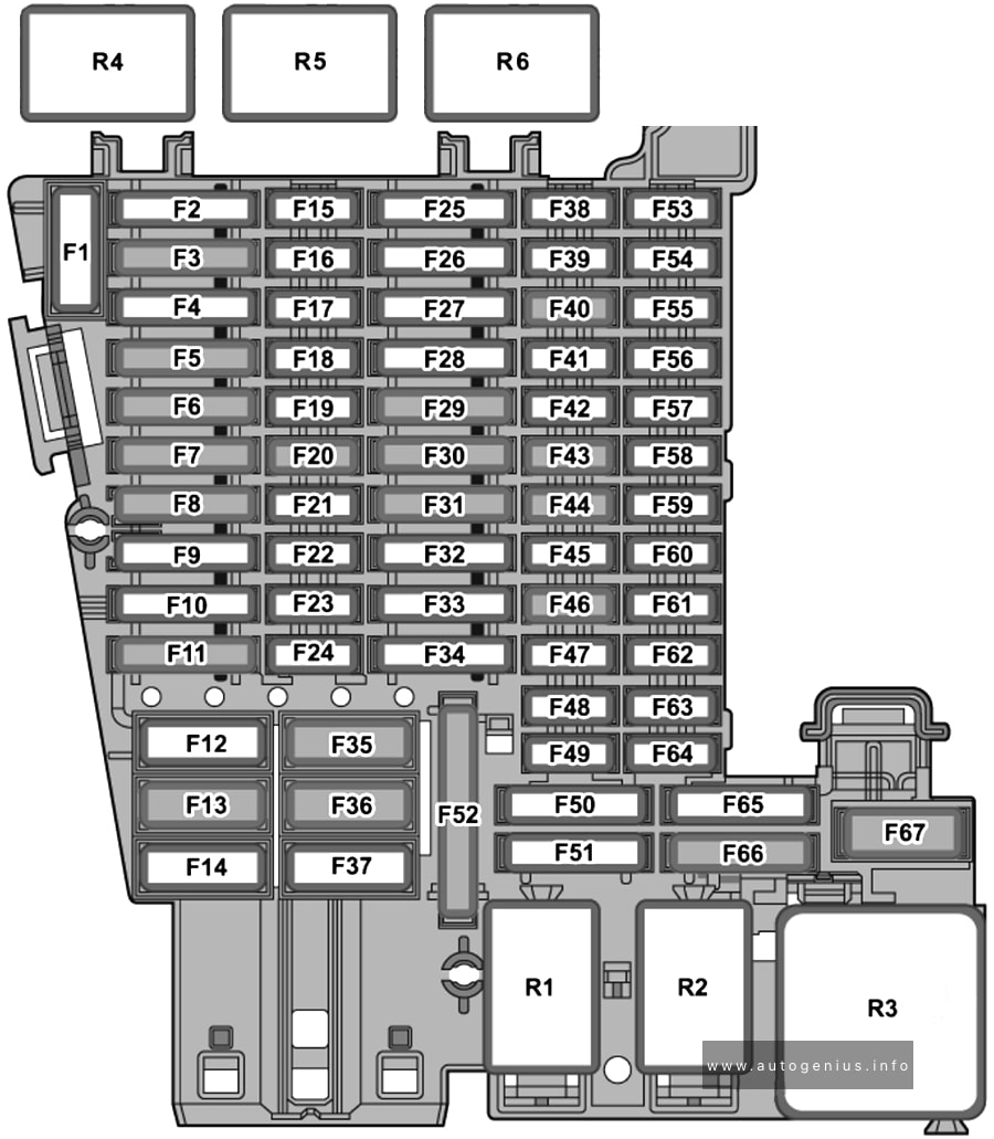
Fuse Box Diagram (Version 2, High)
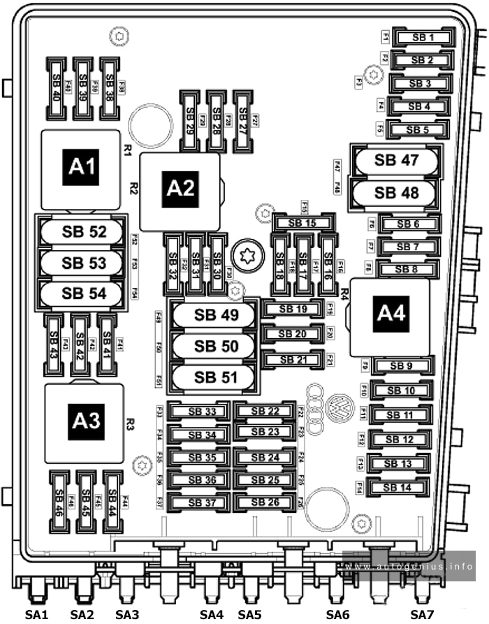
Assignment of the fuses in the engine compartment (Version 2, High)
| № | Amps | Function/Component |
|---|---|---|
| F1 | 30A | From January 2006 to May 2006: ABS Control Module |
| F2 | 30A | ABS Control Module (valves) |
| F3 | 20A | Comfort System Central Control Module Transmission Control Module (TCM) |
| F4 | 5A | Vehicle Electrical System Control Module (measuring cable) |
| F5 | 15A | Vehicle Electrical System Control Module (horn) |
| F6 | 15A | Fuel Pressure Regulator Valve |
| F7 | – | Not used |
| F8 | – | Not used |
| F9 | 10A | Turbocharger Recirculating Valve (BPY, BWA) Evaporative Emission (EVAP) Canister Purge Regulator Valve 1 (BPY, BWA) Wastegate Bypass Regulator Valve (BPY, BWA) |
| F10 | – | Not used |
| F11 | 10A | Oxygen Sensor (O2S) Heater |
| F12 | 10A | Oxygen Sensor (O2S) Heater 1 (behind Three Way Catalytic Converter (TWC) |
| F13 | 15A | Direct Shift Gearbox (DSG) Mechatronic |
| F14 | – | Not used |
| F15 | 10A | Coolant Pump |
| F16 | 5A | From January 2006 to May 2006: ABS Control Module From May 2006: Steering Column Electronic Systems Control Module |
| F17 | 5A | Instrument Cluster Control Module |
| F18 | 30A | Amplifier |
| F19 | 15A | Radio Radio/Navigation Display Control Module |
| F20 | 5A | From January 2006 to May 2006: Radio/Navigation Display Control Module From May 2006: Telephone Transceiver |
| F21 | – | Not used |
| F22 | – | Not used |
| F23 | 10A | Engine Control Module (ECM) |
| F24 | 5A | Data Bus On Board Diagnostic Interface |
| F25 | – | Not used |
| F26 | – | Not used |
| F27 | – | Not used |
| F28 | 25A | Engine Control Module (ECM) |
| F29 | 5A | Auxiliary Engine Coolant (EC) Pump Relay |
| F30 | 20A | Auxiliary Heater Control Module |
| F31 | 30A | Windshield Wiper Motor |
| F32 | – | Not used |
| F33 | – | Not used |
| F34 | – | Not used |
| F35 | – | Not used |
| F36 | – | Not used |
| F37 | – | Not used |
| F38 | 10A | Coolant Fan Control (FC) Control Module Camshaft Adjustment Valve 1 |
| F39 | 5A | From January 2006 to May 2006: Brake Pedal Position Sensor From May 2006: Clutch Position Sensor |
| F40 | 20A | Ignition Coil 1-4 with Power Output Stage |
| F41 | – | Not used |
| F42 | 5A | From January 2006 to May 2006: Engine Component Power Supply Relay |
| F43 | 30A | From January 2006 to May 2006: Ignition Coil 1-6 with Power Output Stage |
| F44 | – | Not used |
| F45 | – | Not used |
| F46 | – | Not used |
| F47 | 40A | Vehicle Electrical System Control Module |
| F48 | 40A | Vehicle Electrical System Control Module |
| F49 | 40A | Power Supply Relay 2 (terminal 15) |
| F50 | – | Not used |
| F51 | 40A | From January 2006 to May 2006: Secondary Air Injection (AIR) Pump Relay |
| F52 | 40A | Load Reduction Relay |
| F53 | – | Not used |
| F54 | 40A | Driver’s Power Seat Adjustment Circuit Breaker 1 Sunroof Circuit Breaker |
| SA1 | 150A/200A | Generator (GEN) (90A/120A) Generator (GEN) |
| SA2 | 80 A | Power Steering Control Module Electro-mechanical Power Steering Motor |
| SA3 | 50A | Coolant Fan Control (FC) Control Module Coolant Fan Coolant Fan 2 |
| SA4 | 40A | Preheating Coolant, High Heat Output Relay |
| SA5 | 80A | Fuse 17 (on fuse panel C) Fuse 16 (on fuse panel C) Fuse 15 (on fuse panel C) Fuse 14 (on fuse panel C) Fuse 13 (on fuse panel C) Fuse 12 (on fuse panel C) Fuse Panel C |
| 508 | – | Terminal 30 feed (battery in engine compartment) |
| SA6 | 80A | Auxiliary Air Heater Control Module Auxiliary Air Heater Heating Element |
| SA7 | 40A | Convertible Top Hydraulic Pump |
| A1 | Motronic Engine Control Module (ECM) Power Supply Relay | |
| A2 | Auxiliary Engine Coolant (EC) Pump Relay | |
| A3 | – | |
| A4 | Engine Component Power Supply Relay |
WARNING: Terminal and harness assignments for individual connectors will vary depending on vehicle equipment level, model, and market.