Mitsubishi Colt (Z30; 2009 – 2012) – fuse and relay box diagram
Year of production: 2009, 2010, 2011, 2012
This article covers the facelifted Mitsubishi Colt (Z30), produced from 2009 to 2012. It includes fuse box diagrams for the 2009, 2010, 2011, and 2012 models, provides information on the locations of the fuse panels within the vehicle, and details the function of each fuse and relay (fuse layout).
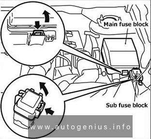
Passenger Compartment Fuse Box
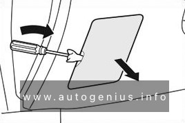
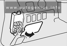
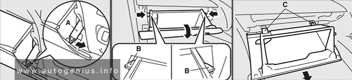
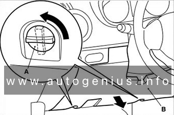
Fuse Box Location
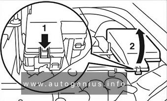
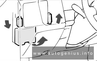
It is located behind the cover in front of the driver’s seat. Turn the clips (A) anticlockwise, then remove the cover (B).
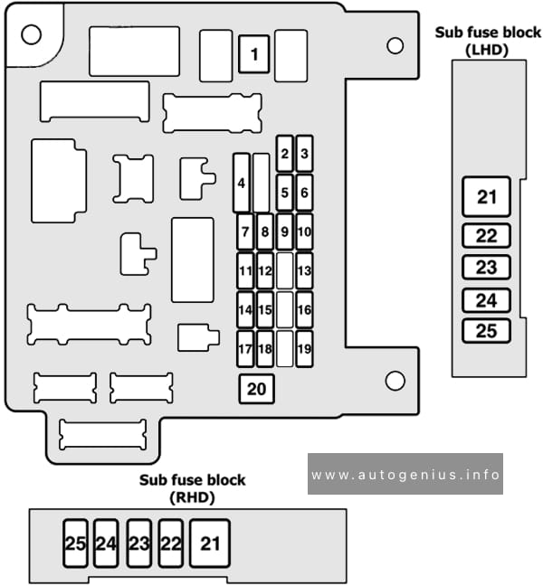
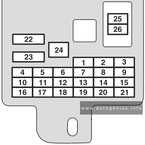
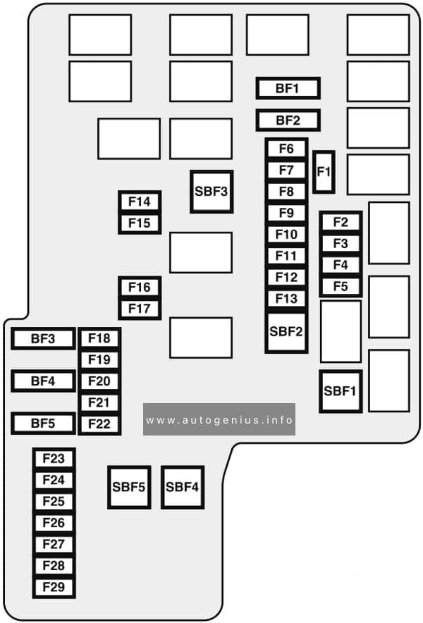
Fuse Box Diagram
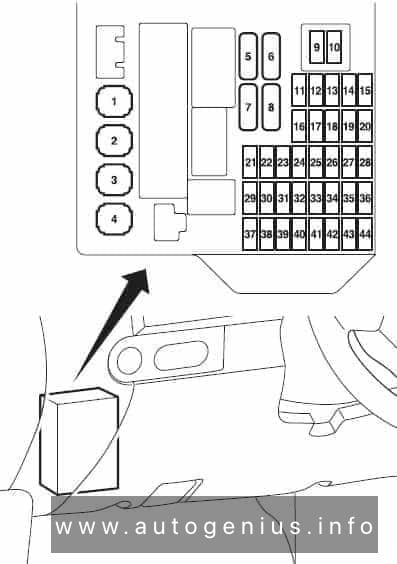
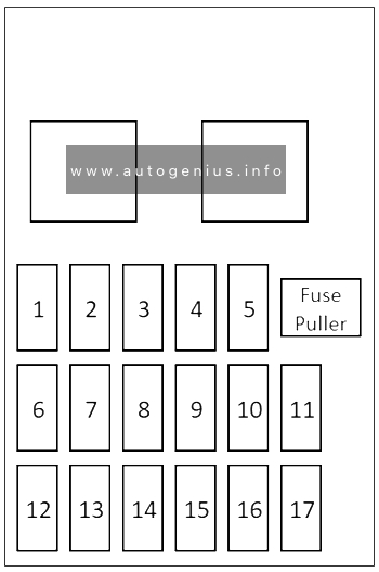
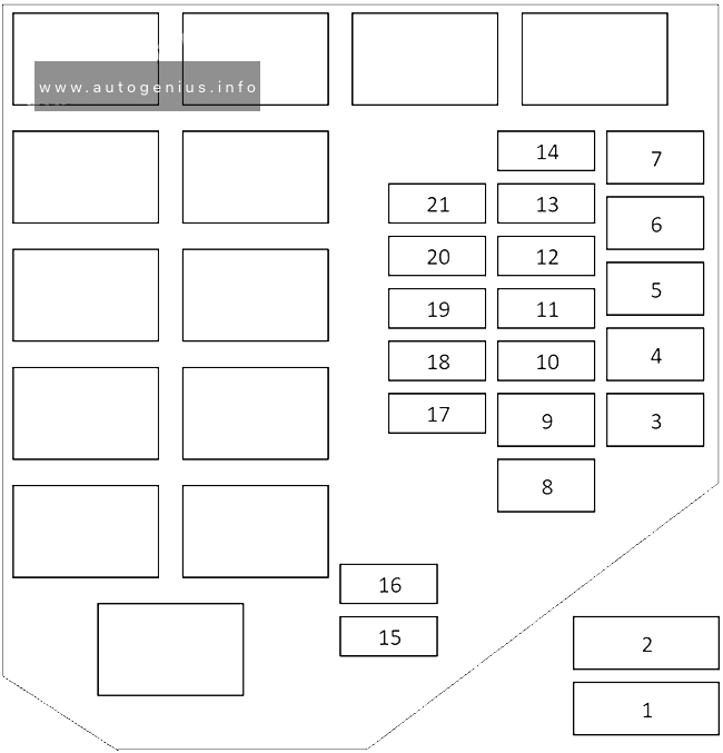
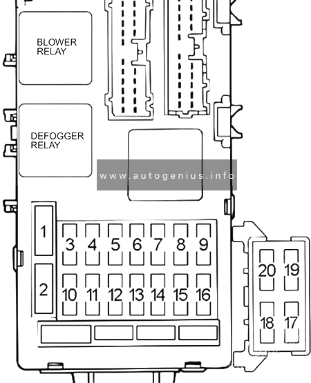
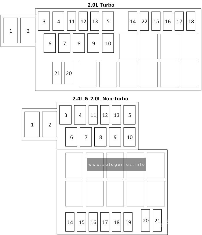
Assignment of the fuses in the instrument panel
| № | Amp | Function |
|---|---|---|
| 1 | 40 | Ignition switch |
| 2 | 40 | Electric window system |
| 3 | 40 | Radiator fan |
| 4 | 40 | Automated manual transmission |
| 5 | 30 | Demister |
| 6 | 30 | Heated seat |
| 7 | — | — |
| 8 | 40 | Heater |
| 9 | 10 | Radio |
| 10 | 10 | Room lamp |
| 11 | 7.5 | Heated door mirror |
| 12 | 7.5 | Electronic control module |
| 13 | 20 | Windscreen wiper |
| 14 | 7.5 | Tail lamp (right) |
| 15 | 7.5 | Tail lamp (left) |
| 16 | 20 | Engine |
| 17 | 15 | Fuel pump |
| 18 | 10 | Horn |
| 19 | 10 | Headlamp high-beam (left) |
| 20 | 10 | Headlamp high-beam (right) |
| 21 | — | — |
| 22 | — | — |
| 23 | 7.5 | Outside rear-view mirrors |
| 24 | 7.5 | Rear fog lamp |
| 25 | 15 | Accessory socket |
| 26 | 15 | Rear window wiper |
| 27 | — | — |
| 28 | — | — |
| 29 | — | — |
| 30 | — | — |
| 31 | 10 | Hazard warning flasher |
| 32 | — | — |
| 33 | 15 | Door locks |
| 34 | 15 | Front fog lamps |
| 35 | 10 | Headlamp low beam (left) |
| 36 | 10 | Headlamp low beam (right) |
| 37 | 7.5 | Reversing lamp |
| 38 | 7.5 | Engine control |
| 39 | 10 | Ignition coil |
| 40 | 7.5 | Gauge |
| 41 | 7.5 | Relay |
| 42 | 15 | Stop lamps |
| 43 | 7.5 | Air conditioning |
| 44 | — | — |
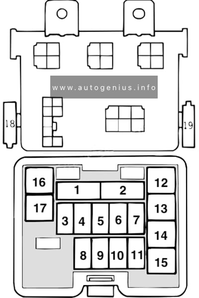
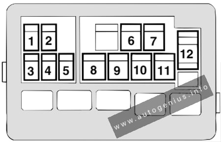
Relays
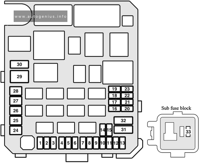
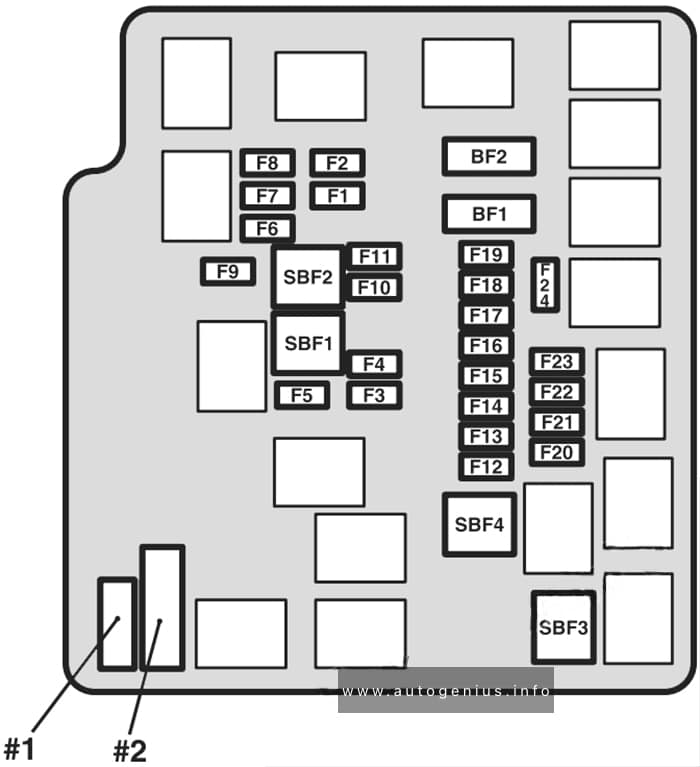
Fuse Box Diagram
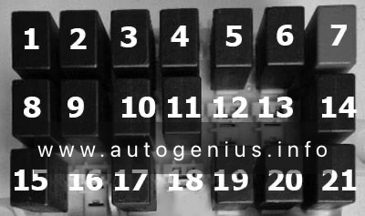
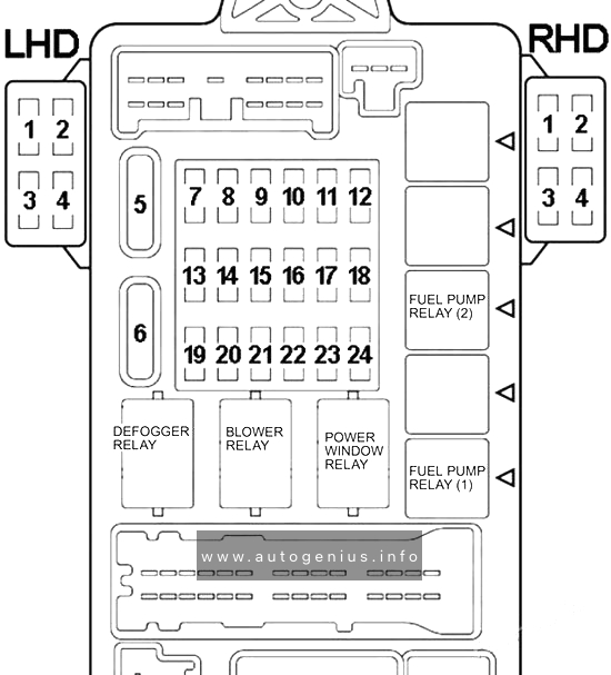
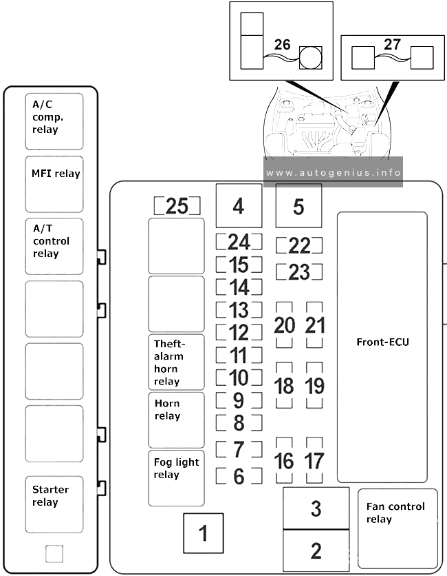
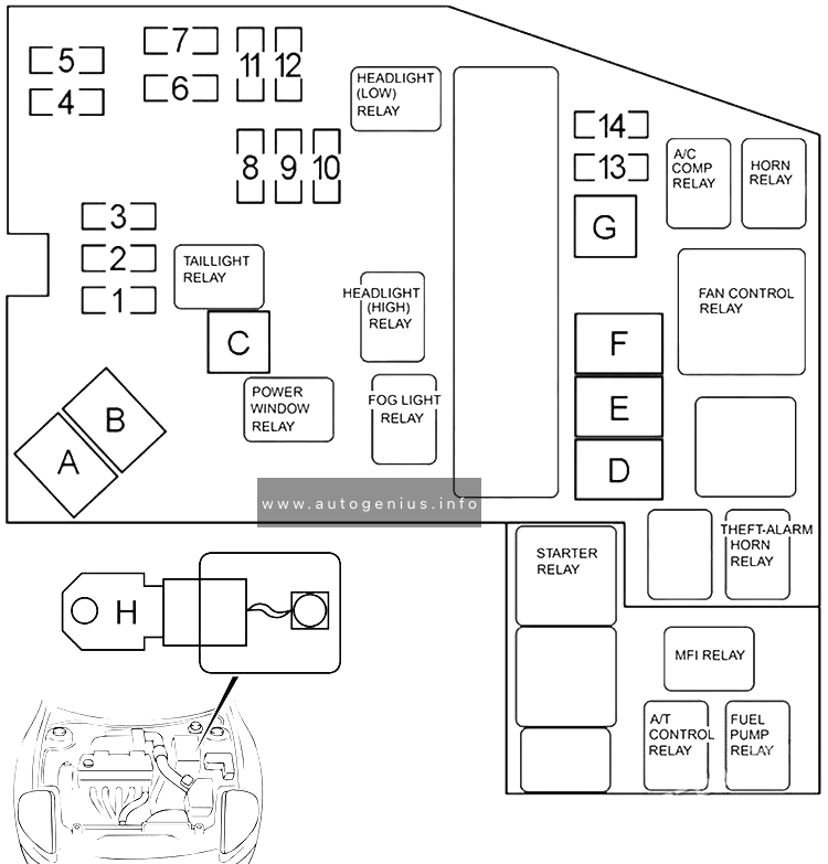
Assignment of the relays in the passenger compartment
| № | Relay |
|---|---|
| 1 | Power windows relay |
| 2 | Horn relay |
| 3 | — |
| 4 | Rear fog light relay |
| 5 | Starter relay |
| 6 | Engine management relay |
| 7 | — |
| 8 | — |
| 9 | Fog light relay |
| 10 | Heater fan relay |
| 11 | — |
| 12 | Transmission Control Relay |
| 13 | Power connector for additional equipment |
| 14 | — |
| 15 | — |
| 16 | Washers relay |
| 17 | Rear heated window relay |
| 18 | Seat heating relay |
| 19 | Low beam headlight relay |
| 20 | High beam headlight relay |
| 21 | — |
WARNING: Terminal and harness assignments for individual connectors will vary depending on vehicle equipment level, model, and market.