Volkswagen Passat (B8; 2015 – 2019) – fuse and relay box diagram
Year of production: 2014, 2015, 2016, 2017, 2018, 2019
This article covers the eighth-generation Volkswagen Passat (B8), manufactured from 2014 to 2022. It includes fuse box diagrams for the 2014 through 2019 models, provides information on the locations of the fuse panels inside the vehicle, and details the purpose and layout of each fuse and relay.
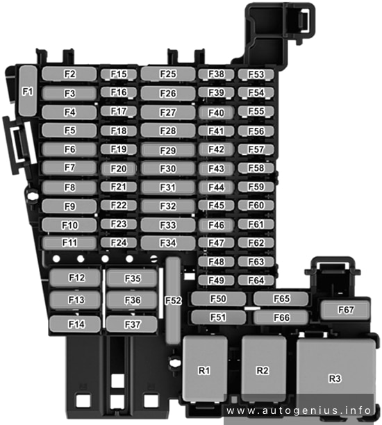
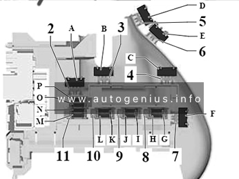
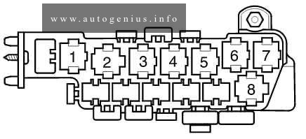
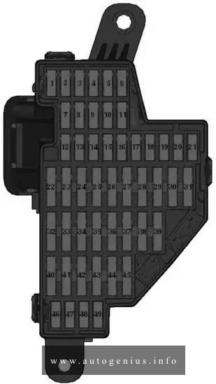
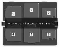
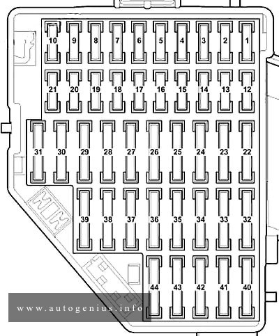
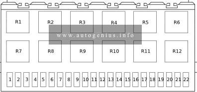
Passenger Compartment Fuse Box (Fuse Panel C -SC-)
Fuse Box Diagram
Assignment of the fuses in the instrument panel fuse box
| № | Amps | Function / component |
|---|---|---|
| SC1 | 30 A | Control unit for reducing agent heater |
| SC2 | 10 A | Steering column electronics control unit |
| SC3 | – | – |
| SC4 | 7.5 A | Alarm horn |
| SC5 | 5 A / 7.5 A | Data bus diagnostic interface |
| SC6 | 5 A / 7.5 A | Anti-theft alarm sensor Selector lever |
| SC7 | 10 A | Heater and air conditioning controls Selector lever Remote control receiver for auxiliary coolant heater Heated rear window relay Analogue clock Operating and display unit for rear air conditioning system Tyre Pressure Monitoring System control unit Magnetic clutch relay |
| SC8 | 10 A / 7.5 A | Rotary light switch Electromechanical parking brake button Rain and light sensor Diagnostic connection Anti-theft alarm sensor Front interior light Light for left dashboard background lighting Light for right dashboard background lighting Light for front left door contour lighting Light for front right door contour lighting Light for rear left door contour lighting Light for rear right door contour lighting Control unit for cornering light and headlight range control |
| SC9 | 1 A / 5 A / 7.5 A | Steering column electronics control unit |
| SC10 | 7.5 A / 10 A | Display unit for front information display and operating unit control unit TV tuner Control unit for Head-up Display CD player |
| SC11 | 25 A / 40 A | Control unit for front left belt tensioner Onboard supply control unit Front left headlight |
| SC12 | 5 A / 7.5 A / 20 A | Control unit 1 for information electronics |
| SC13 | 15 A / 25 A | Electronically controlled damping control unit Control unit for front left belt tensioner |
| SC14 | 30 A / 40 A | Fresh air blower control unit |
| SC15 | 10 A | Control unit for electronic steering column lock |
| SC16 | 7.5 A | Two-way signal amplifier for mobile telephone/data services Storage compartment with interface for mobile telephone USB hub Chip card reader TV tuner |
| SC17 | 5 A / 7.5 A | Dash panel insert Emergency call module control unit and communication unit Telematics control unit for real-time monitoring |
| SC18 | 7.5 A | Reversing camera Rear lid handle release button Control unit for overhead view camera Rear overhead view camera |
| SC19 | 7.5 A | Interface for entry and start system |
| SC20 | 7.5 A / 10 A | Relay for reducing agent metering system |
| SC21 | 15 A | All-wheel drive control unit |
| SC22 | 15 A | Trailer detector control unit |
| SC23 | 40 A / 20 A | Onboard supply control unit Front right headlight Sliding sunroof adjustment control unit |
| SC24 | 30 A / 40 A | Sliding sunroof adjustment control unit Onboard supply control unit Front right headlight |
| SC25 | 30 A | Driver door control unit (Only left-hand drive models) Front passenger door control unit (Only right-hand drive models) Rear left door control unit Rear left window regulator motor |
| SC26 | 30 A | Onboard supply control unit Seat heating |
| SC27 | 30 A / 40 A | Digital sound package control unit Onboard supply control unit |
| SC28 | 20 A / 25 A | Trailer detector control unit |
| SC29 | – | – |
| SC30 | 10 A | High-voltage battery 1 Maintenance connector for high-voltage system |
| SC31 | 30A / 40 A | Onboard supply control unit Front left headlight Rear lid control unit |
| SC32 | 7.5 A / 10 A | Front camera for driver assist systems Adaptive cruise control unit Parking aid control unit Park assist steering control unit Blind Spot Monitor control unit Blind Spot Monitor control unit 2 |
| SC33 | 5 A / 7.5 A | Airbag control unit Warning lamp for airbag deactivated on front passenger side |
| SC34 | 7.5 A | Electromechanical parking brake button Interior mirror Relay for power sockets Pedestrian protection warning lamp Switch module 2 in centre console Pressure sender for refrigerant circuit External air quality and air humidity sensor |
| SC35 | 7.5 A / 10 A | Diagnostic connection Headlight range control and instrument illumination regulator Control unit for cornering light and headlight range control Front left headlight Left headlight range control motor Front right headlight Right headlight range control motor |
| SC36 | 5 A / 7.5 A | Front right headlight Output module 1 for right LED headlight |
| SC37 | 5 A / 7.5 A | Front left headlight Output module 1 for left LED headlight |
| SC38 | 25 A | Trailer detector control unit |
| SC39 | 30 A | Front passenger door control unit (Only left-hand drive models) Driver door control unit (Only right-hand drive models) Rear right door control unit Rear right window regulator motor |
| SC40 | 20 A | Cigarette lighter 12V socket 12V socket 2 12V socket 3 |
| SC41 | 25 A | Control unit for front right belt tensioner |
| SC42 | 40 A | Onboard supply control unit Central locking |
| SC43 | 30 A / 40 A | Onboard supply control unit Digital sound package control unit |
| SC44 | 15 A | Trailer detector control unit |
| SC45 | 15 A | Driver seat lumbar support adjustment switch Driver seat adjustment operating unit Driver seat adjustment control unit Operating unit for front left seat adjustment Massage control unit Front left seat cushion fan 1 Front left seat backrest fan 1 |
| SC46 | 30 A | DC/AC converter with socket, 12V – 230V |
| SC47 | 15 A / 7.5 A | Rear window wiper motor Rear roller blind control unit |
| SC48 | 7.5 A | Engine sound generator control unit |
| SC49 | 5 A / 7.5 A | Clutch position sender Starter relay 1 Starter relay 2 High-voltage battery 1 |
| SC50 | 40 A | Rear lid control unit |
| SC51 | 25 A | Operating and display unit for rear air conditioning system |
| SC52 | 15 A | Electronically controlled damping control unit |
| SC53 | 30 A | Heated rear window relay |
| R1 | Relay for reducing agent metering system | |
| R2 | Magnetic clutch relay | |
| R3 | – | |
| R4 | Terminal 15 voltage supply relay | |
| R5 | Heated rear window relay | |
| R6 | Relay for power sockets |
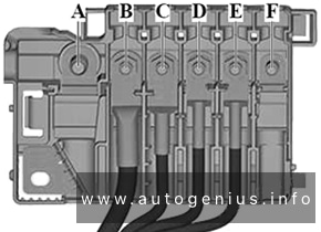
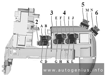
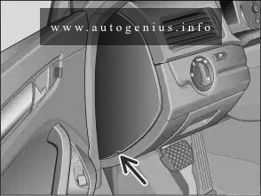
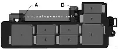
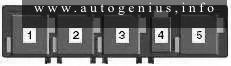
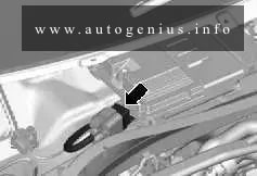
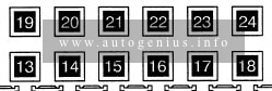
Fitting location of front passenger seat adjustment thermal fuse
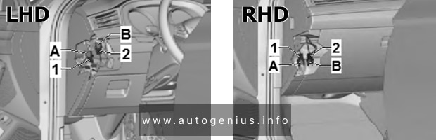
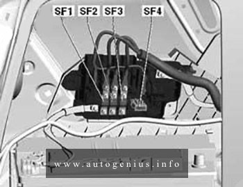
Assignment of the fuses in the front passenger seat adjustment thermal fuse
| № | Amps | Function/component |
|---|---|---|
| A | 15 A | Operating unit for front right seat adjustment Front right lumbar support adjustment switch Front right seat cushion fan 1 Front right seat backrest fan 1 |
| B | – |
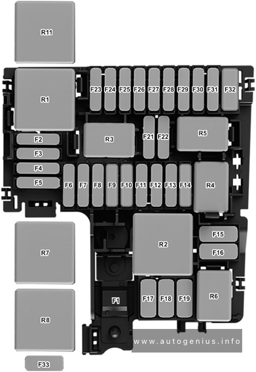
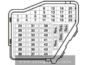
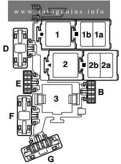
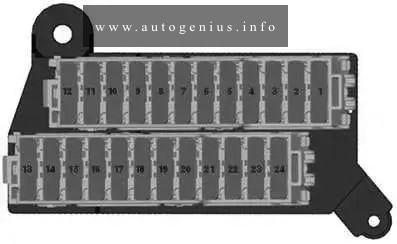
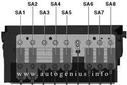
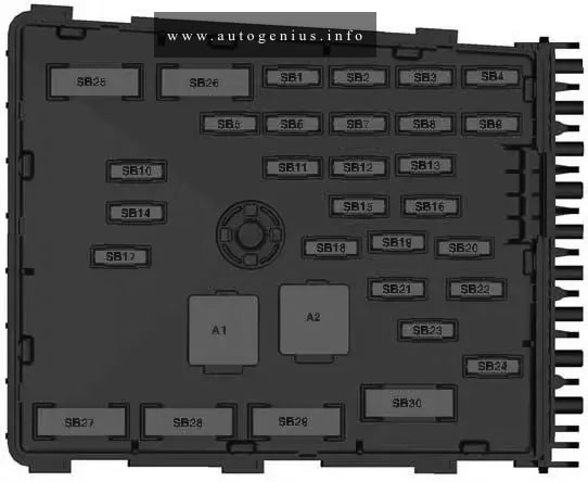
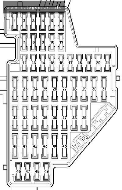
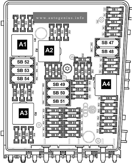
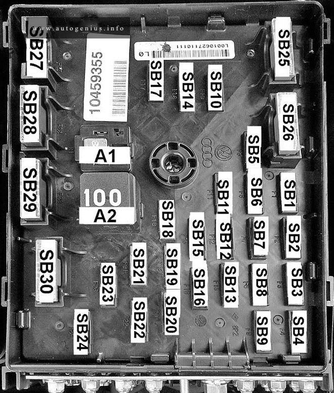
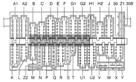
Engine Compartment Fuse Box (Fuse panels B -SB- & A -SA-)
Fuse Box Diagram
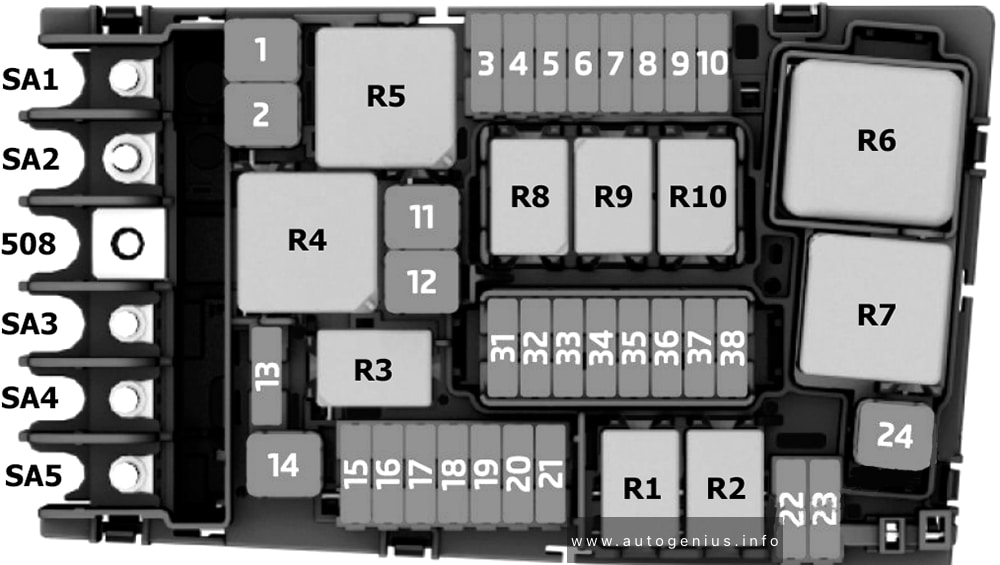
Assignment of the fuses in the engine compartment fuse box
| № | Amps | Function / component |
|---|---|---|
| SB1 | 25 A / 40 A | ABS control unit |
| SB2 | 40 A | ABS control unit ABS hydraulic pump |
| SB3 | 15 A / 30 A | Engine/motor control unit |
| SB4 | 10 A / 5 A / 7.5 A | Radiator fan Oil level and oil temperature sender Relay for reducing agent metering system High heat output relay Low heat output relay Charge pressure positioner Activated charcoal filter solenoid valve 1 Exhaust camshaft control valve 1 Camshaft control valve 1 Valve for oil pressure control Inlet cam actuator for cylinder 2 Exhaust cam actuator for cylinder 2 Inlet cam actuator for cylinder 3 Exhaust cam actuator for cylinder 3 Fuel cooling valve Exhaust gas recirculation cooler changeover valve Charge pressure control solenoid valve Turbocharger air recirculation valve Power steering control unit |
| SB5 | 10 A | Fuel pressure regulating valve Fuel metering valve Camshaft control valve 1 Exhaust cam actuator A for cylinders 1-4 Exhaust cam actuator B for cylinders 1-4 Injector, cylinders 1-4 Engine component current supply relay Coolant valve for gearbox Coolant pump for high-voltage battery Coolant pump for high-temperature circuit |
| SB6 | 5 A / 7.5 A | Brake light switch |
| SB7 | 10 A / 15 A / 7.5 A | Fuel metering valve Circulation pump Radiator blind control motor Coolant valve for cylinder head Valve for oil pressure control Exhaust gas recirculation cooler changeover valve Charge pressure positioner Coolant pump for high-temperature circuit Charge air cooling pump Auxiliary pump for heating Coolant valve for gearbox Coolant shut-off valve Gearbox oil cooling pump Fuel pressure regulating valve Coolant changeover valve 2 Coolant changeover valve 1 Coolant pump for low-temperature circuit |
| SB8 | 10 A / 15 A | Lambda probe 1 before catalytic converter Lambda probe heater Lambda probe 1 after catalytic converter Lambda probe 1 heater after catalytic converter NOx sender |
| SB9 | 20 A / 5 A / 10 A / 7.5 A | Ignition coils 1-4 with output stage Heater element for crankcase breather Automatic glow period control unit Air mass meter Charge air cooling pump Activated charcoal filter solenoid valve 1 Exhaust camshaft control valve 1 Camshaft control valve 1 |
| SB10 | 20 A / 10 A / 15 A | Fuel pump control unit |
| SB11 | 40 A | Auxiliary air heater element |
| SB12 | 40 A | Auxiliary air heater element |
| SB13 | 30 A / 15 A / 7.5 A | Mechatronic unit for dual clutch gearbox Dual clutch gearbox Auxiliary hydraulic pump 1 for gearbox oil Brake servo |
| SB14 | 40 A / 30 A | Heated windscreen relay |
| SB15 | 15 A | Horn relay |
| SB16 | 10 A / 20 A | Engine component current supply relay Power and control electronics for electric drive Charging unit 1 for high-voltage battery |
| SB17 | 7.5 A | Main relay Terminal 30 voltage supply relay Engine/motor control unit ABS control unit Heated windscreen relay |
| SB18 | 5 A / 7.5 A | Battery monitor control unit Data bus diagnostic interface |
| SB19 | 30 A | Wiper motor control unit |
| SB20 | 10 A | Alarm horn |
| SB21 | 30 A / 15 A | Heated windscreen relay 2 Mechatronic unit for dual clutch gearbox Dual clutch gearbox Auxiliary hydraulic pump 1 for gearbox oil |
| SB22 | 5 A / 7.5 A | Engine/motor control unit |
| SB23 | 30 A | Starter |
| SB24 | 40 A | Auxiliary air heater element Brake servo |
| SB25 | – | – |
| SB26 | – | – |
| SB27 | – | – |
| SB28 | – | – |
| SB29 | – | – |
| SB30 | – | – |
| SB31 | – | – |
| SB32 | 30 A | Heated windscreen (Only models with battery at rear) |
| SB33 | 15 A / 30 A | Mechatronic unit for dual clutch gearbox Dual clutch gearbox Brake system pressure accumulator |
| SB34 | 5 A / 30 A | Brake servo Heated windscreen (Only models with battery at front) |
| SB35 | 30 A / 7.5 A | Wiper motor control unit Air conditioning system relay |
| SB36 | – | – |
| SB37 | 20 A | Auxiliary heater control unit |
| SB38 | – | – |
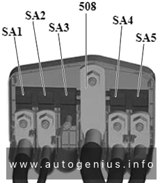
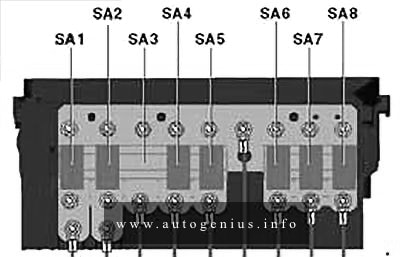
| SA1 | 125 A / 80 A | Supply for fuse holder C -SC- Fuses on fuse holder C: 2, 14, 22, 31, 38, 41, 46, 51, 53 Relay for power sockets Terminal 15 voltage supply relay Radiator fan (Only models with battery at rear) |
| SA2 | 400 A | Alternator |
| SA3 | 80 A | Power steering control unit (Only models with battery at front) |
| SA4 | 80 A | Supply for fuse holder C Terminal 30 Fuses on fuse holder C: 1, 3, 15, 21, 23, 28, 43, 45, 50 Power steering control unit (Only models with battery at rear) |
| SA5 | 50 A | Radiator fan Supply for fuse 4 on fuse holder A Power steering control unit (Only models with battery at rear) |
| R1 | Starter relay 1 | |
| R2 | Starter relay 2 | |
| R3 | Horn relay | |
| R4 | High heat output relay (Only models with auxiliary air heater) | |
| R5 | Main relay (Only models with petrol engine) Terminal 30 voltage supply relay (Only models with diesel engine) |
|
| R6 | Automatic glow period control unit (Only models with diesel engine) Coolant shortage indicator control unit (Only models with hybrid drive system) |
|
| R7 | Low heat output relay (Only models with auxiliary air heater) | |
| R8 | Air conditioning system relay (Only models with hybrid drive system) Engine component current supply relay (Only models with a 1.8–2.0l petrol engine) |
|
| R9 | Heated windscreen relay 1 | |
| R10 | Heated windscreen relay 2 |
WARNING: Terminal and harness assignments for individual connectors will vary depending on vehicle equipment level, model, and market.