Volkswagen Polo (6R/MK5; 2009 – 2017) – fuse and relay box diagram

Volkswagen Polo (6R/MK5; 2009 – 2017) – fuse and relay box diagram

Year od production: 2009, 2010, 2011, 2012, 2013, 2014, 2015, 2016, 2017


This article focuses on the fifth-generation Volkswagen Polo (6R/6C/61), produced from 2009 to 2018. It includes fuse box diagrams for models from 2009 to 2017, provides information on the location of the fuse panels inside the vehicle, and details the fuse and relay assignments (fuse layout).

Passenger Compartment Fuse Box

Fuse Box Location

The fuse box is located behind the cover below the steering wheel.


Fuse Box Diagram

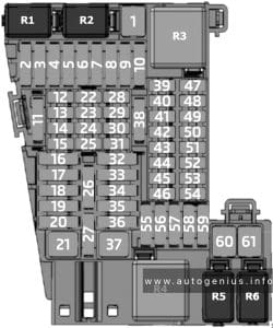
Volkswagen Polo (6R/MK5; 2009 - 2017) - fuses and relay box diagram - passenger compartment
Volkswagen Polo (6R/MK5; 2009 – 2017) – fuses and relay box diagram – passenger compartment


Assignment of the fuses in the passenger compartment

Amp Component
F1 5A Control unit in dash panel insert
ABS control unit
Mobile telephone operating electronics control unit
F2 10A Steering column combination switch
On-board supply control unit
Rear window wiper motor
Windscreen and rear window washer pump
F3 5A Fuel pump relay
Engine control unit
Fuel supply relay
Fuel pump control unit
Control unit for structure-borne sound
F4 2A (2A) Combination switch
F5
F6 5A Instrumentation control module
F7 5A Headlight range control regulator
Number plate left light
Number plate right light
On-board supply control unit
F8 10A Engine management system
F9 5A/7.5A TCS and ESP button
Tyre pressure monitor display button
Steering angle sender
ABS control unit
Stop/start system button
Data bus diagnostic interface
F10 5A Cruise control system switch
Steering column combination switch
Brake light switch
Clutch pedal switch
On-hoard supply control unit
F11 5A/10A Headlight range control regulator
Left headlight range control motor
Right headlight range control motor
Cruise control system switch
On-hoard supply control unit
Cornering light and headlight range control unit
F12 5A Door mirror adjustment switch
F13 5A Transmission control module (TCM)
F14 5A Supplementary restraint system (SRS) control module
F15 5A Heated windscreen waterjets
F16 5A Parking aid control module
F17
F18 5A Rear fog light cut-out contact switch
Control unit in dash panel insert
Rear left fog light bulb
On-board supply control unit
F19 5A Multifunction control module
F20 5A Steering angle sender
Control unit in dash panel insert
Fuel supply relay
Terminal 30 voltage supply relay
Low heat output relay
High heat output relay
F21 10A Multifunction control module
F22 5A Diagnostic connection
Climatronic control unit
Air conditioning system control unit
Mobile telephone operating electronics control unit
Ignition key withdrawal lock solenoid
F23 5A Selector lever Rain sensor
On-hoard supply control unit
Engine control unit
Data bus diagnostic interface
F24 5A On-board supply control unit
Driver side heated exterior mirror
Front passenger side heated exterior mirror
F25 5A High pressure sender
Heater control unit
Radiator fan control unit
Air conditioning system control unit
Trailer detector control unit
Diagnostic connection
Humidity sender
Radiator fan control unit
Voltage stabiliser
Voltage stabiliser 2
F26 7,5A Air mass meter
Oil level and oil temperature sender
Power steering control unit
Heater element for crankcase breather
Starter relay 1
Starter relay 2
F27 7,5A Reversing lamps
F28 10A Engine management system
F29 10A Engine management system
F30 10A Engine management system
F31 5A/10A Engine management system
F32 10A/15A/20A/30A Engine management system
F33 5A Clutch position sender
Brake light switch
F34 15A Control unit in dash panel insert
Left main beam bulb
Right main beam bulb
On-board supply control unit
Left gas discharge light control unit
Right gas discharge light control unit
F35 15A/20A Engine management system
F36 7,5A Right main beam bulb
F37 25A Seat heater control module
F38 30A Transmission control module (TCM)
F39 10A/15A Right dipped beam bulb
F40 30A AC/heater blower control module
F41 10A Rear screen wiper motor
F42 15A Cigarette lighter 12 V socket
F43 15A Multifunction control module
F44 5A Alarm system
F45 15A Audio system
F46 20A Head lamp washers
F47 20A On-board supply control unit
Windscreen wiper motor
F48 25A Multifunction control module
F49 15A/30A Fuel pump relay
Fuel supply relay
F50 25A Door function control module, driver
F51 25A Door function control module, passenger
F52 30A Rear left door control unit
Rear right door control unit
F53 30A Multifunction control module
F54 15A Front fog lamps
F55 15A/20A Engine management system
F56 15A Day time running lamps
F57 15A Multifunction control module
F58 20A Brake servo vacuum pump
F59 10A/15A Left dipped beam bulb
F60 15A Audio system


The onboard supply control unit

Fuse Box Location

The fuse/relay panel located on left underneath the dashboard.


Fuse Box Diagram

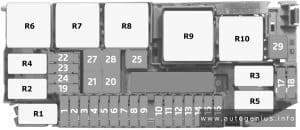
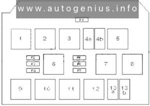
Volkswagen Polo (6R/MK5; 2009 - 2017) - fuses and relay box diagram - passenger compartment (onboard supply control unit)
Volkswagen Polo (6R/MK5; 2009 – 2017) – fuses and relay box diagram – passenger compartment (onboard supply control unit)


Assignment of the fuses in the passenger compartment (onboard supply control unit)

Amp Component
1
2
3 Ignition main circuits relay
4a Headlamp low beam relay
4b Fuel system primer relay
5 ABS protection relay
6 Petrol: Fuel pump (FP) relay
7 Starter motor inhibit relay
8 Ignition auxiliary circuits relay
9 Headlamp washer pump relay
10 Ignition auxiliary circuits relay (08.09)
11
12
13a Starter motor relay
13b Auxiliary heater relay
F1 30A Sunroof control module
F2 40A Engine coolant heater
F3 40A Engine coolant heater
F4 40A Engine coolant heater
F5 20A Trailer control module
F6 20A Trailer control module
F7 15A Trailer control module


Engine Compartment Fuse Box

Fuse Box Location

It is located in the engine compartment on the battery.


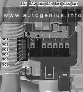
Fuse Box Diagram (Main fuse box)

Volkswagen Polo (6R/MK5; 2009 - 2017) - fuses and relay box diagram - engine compartment (main fuse box)
Volkswagen Polo (6R/MK5; 2009 – 2017) – fuses and relay box diagram – engine compartment (main fuse box)


Assignment of the fuses in the engine compartment (main fuse box)

Amp Component
SA1 150A/175A Alternator
SA2 30A Gas fuel control module
SA3 110A
SA4 50A Power steering control module
SA5 40A ABS control module
SA6 40A Engine coolant blower motor control module
SA7 50A Glow plugs
SC1 25A ABS control module
SC2 30A Engine coolant blower motor control module
SC3 5A Engine coolant blower motor control module
SC4 10A ABS control module
SC5 5A Multifunction control module
SC6 30A Transmission control module (TCM)


WARNING: Terminal and harness assignments for individual connectors will vary depending on vehicle equipment level, model, and market.

Volkswagen Polo (6N/6KV; 1999 – 2002) – fuse and relay box diagram

Volkswagen Polo (6N/6KV; 1999 – 2002) – fuse and relay box diagram

Year od production: 1999, 2000, 2001, 2002


This article covers the third-generation Volkswagen Polo (Typ 6N/6KV), manufactured between 1994 and 2002. It includes fuse box diagrams for the 1999 through 2002 models, details the locations of the fuse panels within the vehicle, and provides information on the fuse and relay assignments (fuse layout)

Passenger Compartment

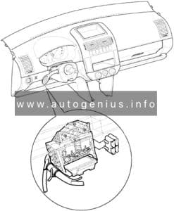
Fuse box location

The fuse box is located behind the cover in driver’s storage compartment.


Fuse box diagram

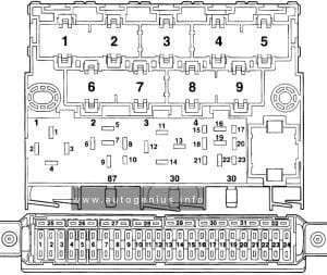
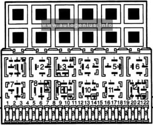
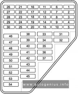
Volkswagen Polo (6N/6KV; 1999 - 2002) - fuses and relay box diagram - passenger compartment
Volkswagen Polo (6N/6KV; 1999 – 2002) – fuses and relay box diagram – passenger compartment


Assignment of the fuses in the instrument panel

Amps Description
SB1 10A Lambda probe heating, ACF; camshaft variable timing adjuster
SB2 5A Number plate lights
SB3 10A Injectors
SB4 5A Side bulb left
SB5 5A Side light bulb
SB6 15A Rear wiper
SB7 75A Turn signals
SB8 5A ABS with EDL/ESP
SB9 5A Headlight range control
SB10 7.5A Interior lighting, glove box, mirror, door entry, luggage compartment light
SB11 5A Self-diagnosis connection voltage supply, dash panel insert, Climatronic
SB12 10A Right headlight main beam, main beam warning lamp
SB13 10A Left main beam headlight
SB14 10A Hazard warning lights system, anti-theft alarm system
SB15 10A Brake lights
SB16 5A Ignition/starter switch S-contact
SB17
SB18 5A Mirror heating
SB19 15A Horn
SB20 10A Telephone/preparationfor telephone
SB21 5A Automatic gearbox control unit
SB22 15A Anti-theft alarm system horn
SB23 5A EGR, air mass meter, addit. heater relay, glow plug relay
SB24 5A Clutch pedal switch (diesel), brake light suppression switch (EPC)
SB25 5A Selector lever switch (AG4)
SB26 7.5A Air conditioner, central locking, electric windows, electric mirrors, navigation
SB27 5A Dash panel insert
SB28 5A Speedometer sender, immobilizer
SB29 75A Reversing lights, washer jet heating, headlight range control motor
SB30 5A Exhaust gas recirculation valve, activated charcoal filter solenoid, heater pipe
SB31 5A Fuel shut-off control unit, engine control unit
SB32 5A Fuel shut-off control unit (diesel)
SB33 10A Automatic gearbox selector lever lock
SB34 10A Ignition transformer
SB35 25A Glass sunroof, fabric sunroof
SB36 15A Engine control unit
SB37 15A Engine control unit
SB38 25A Driver’s door power window
SB39 25A Front passenger’s power window
SB40 15A Fuel pump
SB41 15A Central locking, anti-theft alarm system
SB42 15A Radio, navigation
SB43 15A Fog light, rear fog light
SB44 15A Dipped beam, left headlight
SB45 15A Dipped beam right headlight
SB46 15A Cigarette lighter
SB47 20A Headlight washer system
SB48 20A Heated rear window
SB49 25A Fresh air blower
SB50 15A Windscreen wiper system, windscreen washer pump
SB51 15A Seat heating
Relays:
1 Fuel pump relay (petrol engines only)
Fuel shut-off control unit (diesel engines)
2 Automatic intermittent wash/wipe and rain sensor relay
7 X contact relief relay
8 Heated exterior mirror relay


Engine Compartment

Fuse box location

It is located on the battery.


Fuse box diagram

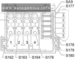
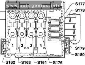
Volkswagen Polo (6N/6KV; 1999 - 2002) - fuses and relay box diagram - engine compartment
Volkswagen Polo (6N/6KV; 1999 – 2002) – fuses and relay box diagram – engine compartment


Assignment of the fuses in the engine compartment

Amps Description
S162 110A Alternator
S163 80A Relay carrier
S164 50A Glow plugs (engine)
S176 50A Glow plugs (radiator fan)
S176 30A Air conditioning system
S177 30A ABS control unit
S178 30A ABS control unit
S179 20A Radiator fan
S180 10A Air conditioning system
SA9 30A Air conditioner – glow plugs (diesel)


WARNING: Terminal and harness assignments for individual connectors will vary depending on vehicle equipment level, model, and market.
Volkswagen Polo (6N/6KV; 1997 – 1998) – fuse and relay box diagram

Volkswagen Polo (6N/6KV; 1997 – 1998) – fuse and relay box diagram

Year od production: 1997, 1998


This article covers the third-generation Volkswagen Polo (Typ 6N/6KV), manufactured between 1994 and 1996. It includes fuse box diagrams for the 1995 through 2002 models, details the locations of the fuse panels within the vehicle, and provides information on the fuse and relay assignments (fuse layout)

Passenger Compartment

Fuse box location

The fuse box is located behind the cover in driver’s storage compartment.


Fuse box diagram

Volkswagen Polo (6N/6KV; 1997 - 1998) - fuses and relay box diagram - passenger compartment
Volkswagen Polo (6N/6KV; 1997 – 1998) – fuses and relay box diagram – passenger compartment


Assignment of the fuses in the instrument panel

Amps Description
1 15A Engine control unit
2 10A Engine control unit (only on petrol engines)
Engine electrics (only on diesel engines)
3 7.5A Engine electrics
4 15A Ignition transformer
5 10A Auto, gearbox control unit, shift lock
6 5A Auto, gearbox control unit
7 5A ABS control unit
8 15A Injectors, Lambda probe
9 10A Engine control unit
10 15A Engine control unit (only on petrol engines)
Engine electrics (only on diesel engines)
11 15A Horn, seat heating
12 10A Right main beam, main beam warning lamp
13 10A Left main beam
14 10A Right dipped beam, right headlight range control, headlight range control adjuster
15 10A Left dipped beam, left headlight range control
16 5A Right side and tail lights
17 5A Left side and tail lights
18 7.5A Reversing light, heated washer jets, selector lever illumination
19 15A Fog lights, rear fog light
20 10A Brake lights
21 10A Hazard warning lights
22 5A Turn signals
23 15A Windscreen wipe/wash system
24 10A Rear window wiper, heated and adjustable exterior mirrors
25 15A Heated rear window
26 5A Dash panel insert, immobiliser
27 5A Self-diagnosis connection, dash panel insert, interior light, luggage compartment light
28 15A Radio, cigarette lighter, central locking
29 5A Interior light, fresh/recirculating air blower actuating motor
30 20A Fresh air blower
31 5A Licence plate lights
32 15A Fuel pump
Relays:
1 Hazard warning light relay
2 Automatic intermittent wipe and wash relay
3 X contact relief relay
4 Fuel pump relay


Engine Compartment

Fuse box location

It is located on the battery.


Fuse box diagram

Volkswagen Polo (6N/6KV; 1997 - 1998) - fuses and relay box diagram - engine compartment
Volkswagen Polo (6N/6KV; 1997 – 1998) – fuses and relay box diagram – engine compartment


Assignment of the fuses in the engine compartment

Amps Description
S162 110A Alternator
S163 50A Relay carrier
S164 50A Engine glow plugs
S176 50A Coolant heater elements
S176 30A Air conditioner
S177 30A ABS control unit
S176 30A ABS control unit
S179 20A Radiator fan
S180 10A Air conditioner


WARNING: Terminal and harness assignments for individual connectors will vary depending on vehicle equipment level, model, and market.
Volkswagen Polo (6N/6KV; 1994 – 1996) – fuse and relay box diagram

Volkswagen Polo (6N/6KV; 1994 – 1996) – fuse and relay box diagram

Year od production: 1994, 1995, 1996


This article covers the third-generation Volkswagen Polo (Typ 6N/6KV), manufactured 1997 and 1998. It includes fuse box diagrams for the 1995 through 2002 models, details the locations of the fuse panels within the vehicle, and provides information on the fuse and relay assignments (fuse layout)

Passenger Compartment

Fuse box location

The fuse box is located behind the cover in driver’s storage compartment.


Fuse box diagram

Volkswagen Polo (6N/6KV; 1994 - 1996) - fuses and relay box diagram - passenger compartment
Volkswagen Polo (6N/6KV; 1994 – 1996) – fuses and relay box diagram – passenger compartment


Assignment of the fuses in the instrument panel

Amps Description
1 10A Dipped beam left, headlight range control, left
2 10A Dipped beam right, headlight range control, right
3 10A Number plate light
4 15A Rear window wiper
5 15A Windscreen wipe/wash system, heated washer jets
6 20A Fresh air blower, air conditioner
7 10A Side light and tail light, right
8 10A Side and tail light, left
9 20A Heated rear window
10 15A Rear fog light
11 10A Main beam, left
12 10A Main beam, right
13 10A Horn
14 15A Reversing lights, additional equipment
15 10A Engine electrics
16 15A Dash panel insert
17 10A Turn signals
18 20A Fuel pump, Lambda probe
19 30A Radiator fan
20 10A Brake light
21 15A Interior lights, dash panel insert, self-diagnosis
22 10A Radio system, cigarette lighter
Relays:
1 Air conditioner relay
2 Rear window wipe/wash relay
3
4 Relief relay for X contact
5
6 Hazard warning light relay
7 Headlight washer system relay
8 Intermittent wipe/wash relay
9 Light switched on. warning buzzer
10 Bridge for fog light
11 Bridge for horn
12 Fuel pump relay
Glow plug relay
Relays above relay plate:
Window lifter relay and/or folding sliding roof
Junction box for terminal
Starter inhibitor relay
Intake manifold preheating relay
Glow period control unit
30A Control unit fuse 1 – ABS (hydraulic pump)
30A Control unit fuse 2 – ABS (valves)
Window lifter thermo fuse and/or folding sliding roof
50A Glow plug fuse


Additional relay carriers:

  • Under driver’s seat: Control unit for heated driver’s seat
  • Under passenger’s seat: Control unit for heated passenger’s seat
  • In engine compartment (left): Radiator fan control unit


WARNING: Terminal and harness assignments for individual connectors will vary depending on vehicle equipment level, model, and market.
Volkswagen Polo (9N; 2002 – 2009) – fuse and relay box diagram

Volkswagen Polo (9N; 2002 – 2009) – fuse and relay box diagram

Year od production:2002, 2003, 2004, 2005, 2006, 2007, 2008, 2009


This article covers the fourth-generation Volkswagen Polo (Mk4/9N), manufactured between 2002 and 2009. It includes fuse box diagrams for models from 2002 through 2009, provides details on the location of the fuse panels within the vehicle, and explains the function and layout of each fuse and relay.

Passenger Compartment Fuse Box

Fuse Box Location

The fuse panel is located behind an access panel on driver’s side edge of the instrument panel.


Fuse Box Diagram

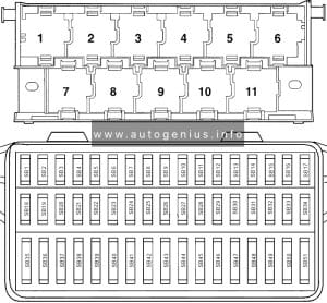
Volkswagen Polo (9N; 2002 - 2009) - fuses and relay box diagram - passenger compartment
Volkswagen Polo (9N; 2002 – 2009) – fuses and relay box diagram – passenger compartment


Assignment of the fuses in the passenger compartment

Amps Function/component
1 10A Rear window wiper motor
2 5A Licence plate light
3 5A Rear left fog light bulb
Trailer socket, rear fog light
4 5A Cruise control system switch
Clutch pedal switch
Brake pedal switch
Radiator fan relay
Fuel pump control unit
5 5A Engine control unit
Exhaust gas recirculation
6 5A Headlight range control regulator
7 7.5A/5A 2002-2004:
Exhaust gas recirculation
Air-mass meter
Oil level sensor
Electrohydraulic steering
Crankcase breather heater element
2005-2009:
Oil level and oil temperature sender
Power steering control unit
Crankcase breather heater element
8 5A Onboard power supply control unit
Mirror heating
9 10A 2002-2004 (FSI):
Lambda probe
Crankcase heater
Pressure regulating valve
10 5A Mobile telephone operating electronics control unit (2006-2009)
Control unit with display for radio and navigation system
Onboard power supply control unit
Radio
11 5A Mirror adjustment switch
Folding exterior mirror control unit
12 5A Right tail light bulb
Right side light bulb
13 5A Left side light bulb
Left tail light bulb
14 10A Crankcase breather heater
Secondary air pump relay
Exhaust gas recirculation
Intake manifold flap
Hall sender
15 10A Multi-function switch
Automatic gearbox control unit
16 10A lntermittent wiper switch
Onboard power supply control unit
Rear window wiper motor
Windscreen and rear window washer pump
17 5A Engine control unit
18 5A Climatic, Climatronic, radiator fan control unit, navigation, circulation pump, illumination of functions, interior monitor sensor, mirror
19 10A Reversing light switch
Parking aid control unit
Left washer jet heater element
Right washer jet heater element
Selector lever illumination (2002-2004)
20 5A Control unit in dash panel insert
21 10A Right main beam bulb
22 10A Left main beam bulb
23 10A Traction control system switch
TCS and ESP button
Tyre pressure monitor display button
Steering angle sender, only models with ESP
ABS control unit
24 10A/15A 2002-2006:
Onboard supply control unit, tank filler flap locking motor
Onboard supply control unit, central locking motor in rear lid
2006-2009:
Heated driver seat regulator
Heated front passenger seat regulator
Heated front seats control unit
25 10A Injectors
Camshaft adjuster
Thermostat heater
Fuel purging valve
26 10A 2002-2004: Brake lights
2005-2009: Coolant pump relay (only BJX)
27 5A Steering angle sender
Control unit in dash panel insert
28 10A Onboard supply control unit, relay for interior lights
Door warning lamp relay
29 5A Climatronic control unit
Air conditioning system control unit
Mobile telephone operating electronics control unit
16-pin connector, diagnostics connection
30 5A Onboard power supply control unit, shift lock, rain sensor
31 25A Driver door control unit
Driver side window regulator motor
32 15A 2002-2004:
Seat heating
2005-2009:
Brake light switch
Brake light suppression relay
33 15A Alarm horn
34 15A/20A 2002-2004:
Socket in luggage compartment (Variant)
2005-2006:
12V socket
2006-2009:
Cigarette lighter
12V socket
Blocking diode
35 20A Sliding sunroof adjustment control unit
36 25A Fresh air blower switch
Fresh air blower control unit
37 15A/20A Ignition transformer
38 25A Rear left door control unit
39 25A Front passenger side door control unit
40 10A/20A/30A Engine control unit
41 15A Fuel pump
42 15A/20A NOx regulator, Lambda probe, exhaust gas cooling
43 15A Right headlight dipped beam bulb
Right headlight range control motor
44 15A Left fog light bulb
Right fog light bulb
45 15A Engine control unit
46 20A Onboard power supply control unit
Automatic intermittent wash and wipe relay
47 20A/30A Onboard power supply control unit
Heated rear window
48 15A Onboard power supply control unit, Turn signals
49 10A/15A 2002-2006:
Cigarette lighter
2006-2009:
Onboard supply control unit, tank filler flap locking motor
Onboard supply control unit, central locking motor in rear lid
50 15A 2002-2004:
Central locking
2005-2009:
Anti-theft alarm ultrasonic sensor
Comfort system central control unit
51 15A Control unit with display for radio and navigation system
Dipped headlight control unit, on/off for Coming home system
Radio
52 20A Headlight washer system relay
Onboard supply control unit
Treble tone horn, Bass tone horn
53 25A Rear right door control unit
54 15A Left headlight dipped beam bulb
Headlight range control motor


Relay panel

The relay panel is located under the driver’s side of the instrument panel.

Volkswagen Polo (9N; 2002 - 2009) - fuses and relay box diagram - passenger compartment (relay panel)
Volkswagen Polo (9N; 2002 – 2009) – fuses and relay box diagram – passenger compartment (relay panel)


Assignment of the fuses in the relay panel

Amps Description
1 2002-2004:
Driving school mode relay
2005-2009:
Secondary air pump relay (engine code BJX)
Folding exterior mirror control unit
2 2005-2009:
Folding exterior mirror control unit
Driving school mode relay
3 Glow plug relay (Diesel engines)
Motronic current supply relay (2002-2007)
4 Fuel pump relay
5 2002-2004:
Warning lamps relay
2005-2007:
Door warning lamps relay
Brake light suppression relay
6 Headlight washer system relay
7 2002-2004: Starter inhibitor relay
2005-2009: Dipped headlight control unit, on/off (coming home system)
8 Low heat output relay (Diesel engines)
Coolant pump relay (2005-2007, engine code BJX)
9 High heat output relay (Diesel engines)
10 Motronic current supply relay
Radiator fan relay (engine codes ASZ, BLT)
Current supply relay (2002-2004)
11 X-contact relief relay
12 Fuel supply relay
13 Fuel pump relay (Petrol engines)
14 40A Diesel engines fuses:
Heater element fuse 1
Heater element fuse 2
Heater element fuse 3
15 2002-2004:
Diesel direct injection system relay
2005-2009:
Terminal 30 voltage supply relay (Diesel engines)
Motronic current supply relay (Petrol engines, not engine codes BUD, BTS)
Fuel pump relay (2005-2007, engine codes BMD, BME)
F1 10A Trailer socket
F2 15A Heated driver seat regulator
Heated front passenger seat regulator
Heated driver seat control unit
Heated front passenger seat control unit
F3 10A/5A Driving school mode
Footwell light switch
Warning buzzer switch
Control unit in dash panel insert (South Africa, from 2006, 5A)
F4 10A Driving school mode
12V socket


Engine Compartment Fuse Box

Fuse Box Location

The main fuse box located on top of the battery in the engine compartment.


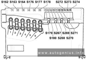
Fuse Box Diagram (version 1)

Volkswagen Polo (9N; 2002 - 2009) - fuses and relay box diagram - engine compartment (version 1)
Volkswagen Polo (9N; 2002 – 2009) – fuses and relay box diagram – engine compartment (version 1)


Assignment of the fuses in the engine compartment (version 1)

Amps Function/component
S162 175A Alternator
S163 110A Fuse holder B
S164 50A Power steering control unit
S176 50A Glow plug activation control unit
Engine glow plugs
Secondary air pump motor
S177 40A Radiator fan (models with air conditioning system or Climatronic)
S178 40A ABS control unit
S179 25A ABS control unit
S180 30A Radiator fan
S267
S268 5A Onboard power supply control unit
S269 5A Radiator fan control unit
S270
S271 5A Automatic gearbox control unit
S272
S273
S274


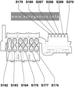
Fuse Box Diagram (version 2)

Volkswagen Polo (9N; 2002 - 2009) - fuses and relay box diagram - engine compartment (version 2)
Volkswagen Polo (9N; 2002 – 2009) – fuses and relay box diagram – engine compartment (version 2)


Assignment of the fuses in the engine compartment (version 2)

Amps Function/component
S162 175A Alternator
S163 110A Fuse holder B
S164 40A Radiator fan (models with air conditioning system or Climatronic)
S176 40A ABS control unit
S177 50A Power steering control unit
S178 50A Glow plug activation control unit
Engine glow plugs
Secondary air pump motor
S179 25A ABS control unit
S180 30A Radiator fan
S267 5A Radiator fan control unit
S268 10A ABS control unit
S269 5A Onboard power supply control unit
S270 5A Diesel direct injection system control unit (models with engine code BMT)
S271 5A Automatic gearbox control unit
S272
S273
S274


WARNING: Terminal and harness assignments for individual connectors will vary depending on vehicle equipment level, model, and market.