Acura CSX (2005 – 2011) – fuse and relay box diagram
Year of production: 2005, 2006, 2007, 2008, 2009, 2010, 2011
This article covers the second-generation Acura CSX, produced from 2005 to 2011. It includes fuse box diagrams for the 2005, 2006, 2007, 2008, 2009, 2010 and 2011 models, provides details on the location of the fuse panels inside the vehicle, and explains the function and layout of each fuse.
Passenger Compartment
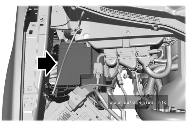
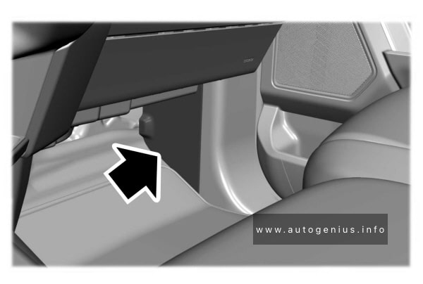
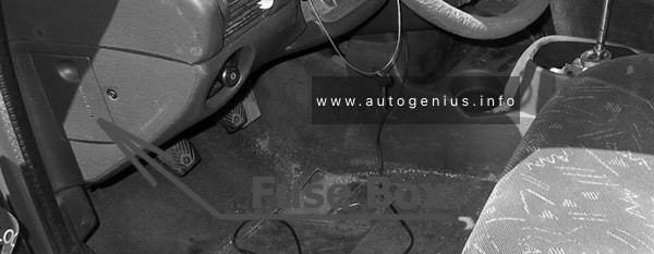
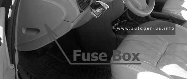
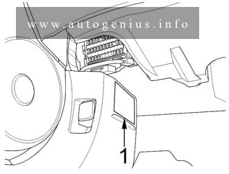
Fuse box location
The interior fuse box is on the driver’s lower left side.
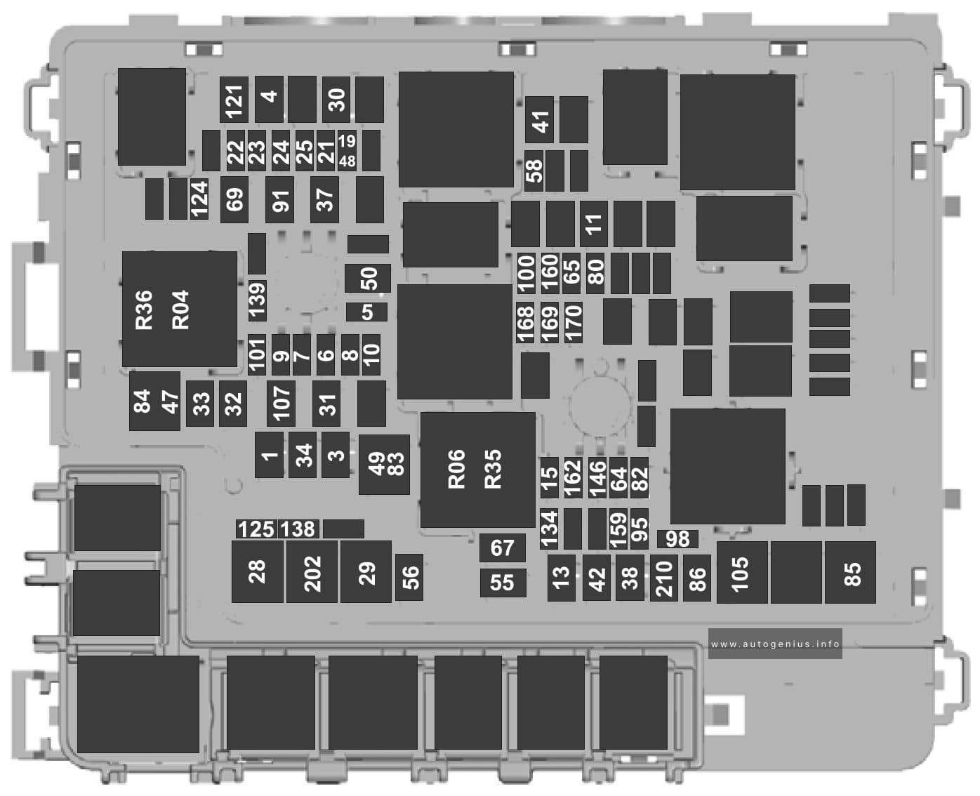
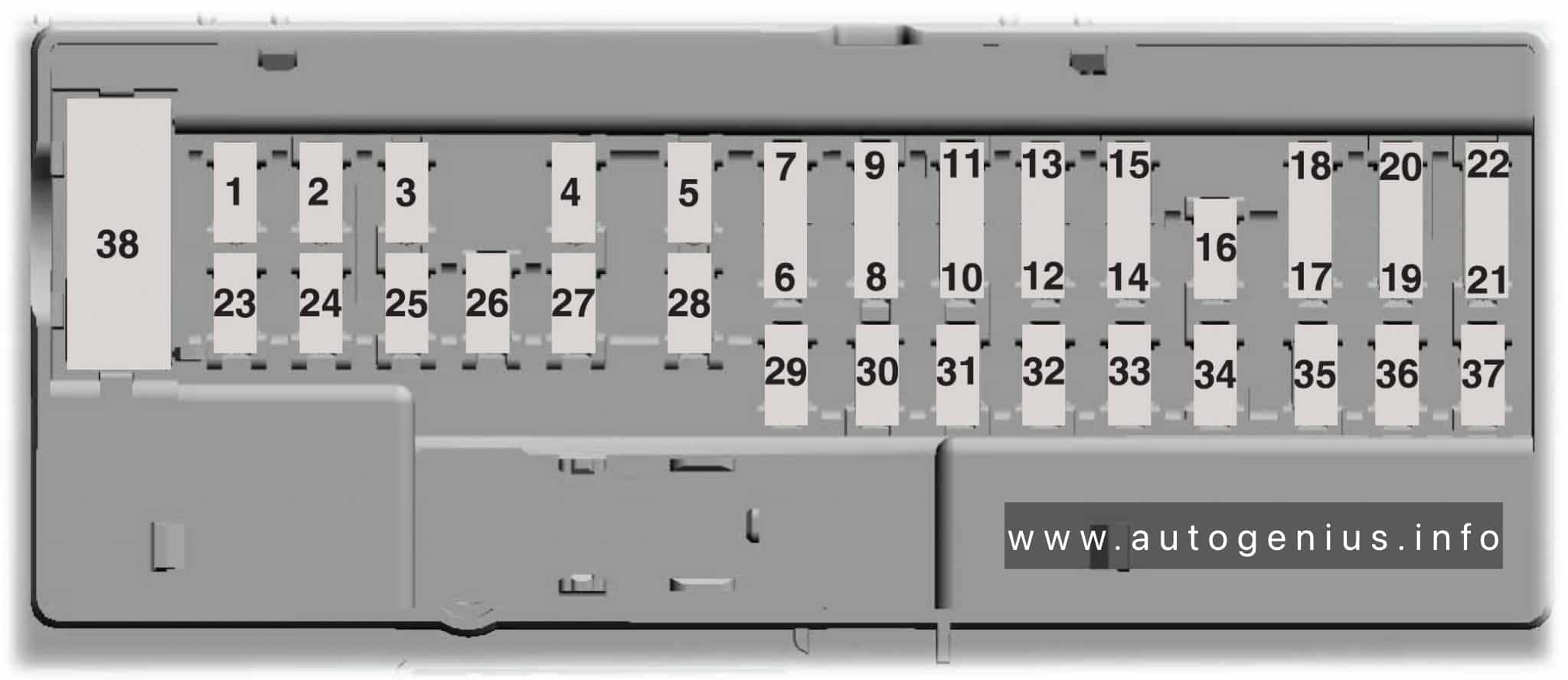
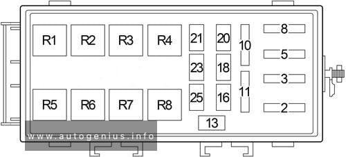
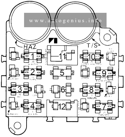
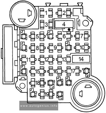
Fuse box diagram
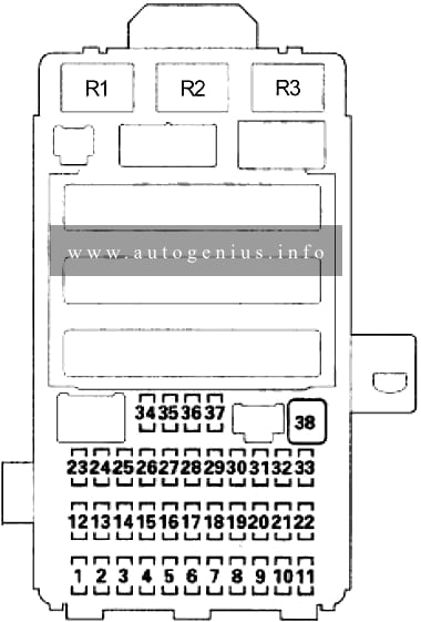
Assignment of the fuses in the passenger compartment
| No. |
A |
Protected Component |
| 1 | 7.5 | Power Mirror Switch Light, Power Window Relay |
| 2 | 15 | Fuel Pump, ECM/PCM, Immobilizer-Keyless Control Unit |
| 3 | 10 | Alternator, CMP Sensor A, ECM/PCM, ELD, EVAP Canister Purge Valve, EVAP Canister Vent Shut Valve. MAF/IAT Sensor, Reverse Lock-Out (Type-S), HO2S (Secondary) |
| 4 | 7.5 | ABS Modulator-Control Unit (’06-’07), EPS Control Unit, VSA Modulator-control Unit (’08-’09), Yaw Rate-lateral Acceleration Sensor (’07-(Type-S) ’08-’09) |
| 5 | 15 | Seat Heater Relays, Seat Heaters |
| 6 | 20 | Fog Light Relay, Fog Lights |
| 7 | 7.5 | TPMS Control Unit |
| 8 | – | – |
| 9 | 7.5 | ODS Unit, Passenger’s Airbag CUTOFF Indicator, SRS Unit |
| 10 | 7.5 | Gauge Control Module (Tach), Back-up Light Switch (MAT), Shift Lock Solenoid (A/T), MICU, TPMS Control Unit (’08-’09) |
| 11 | 10 | SRS Unit |
| 12 | 10 | Right Headlight (High Beam) |
| 13 | 10 | Left Headlight (High Beam) |
| 14 | 7.5 | Audio Unit Light, Climate Control Unit Light, Dash Lights Brightness Controller and Odometer Select/Reset Switch Light, Driver’s Footwell Light, Glove Box Light, Hazard Warning Switch Light. Moonroof Switch Light, Navigation Unit, Passenger’s Airbag CUTOFF Indicator Light, Select/Reset Switch Light, Steering Wheel Switches Light, VSA OFF Switch Light |
| 15 | 7.5 | Parking Lights, Taillights, License Plate Lights, Side Marker Lights |
| 16 | 10 | Right Headlight (Low Beam) |
| 15 | Right HID Unit | |
| 17 | 10 | Left Headlight (Low Beam) |
| 15 | Left HID Unit | |
| 18 | 20 | Headlight High Main, Multiplex Integrated Control Unit (MICU) |
| 19 | 15 | Small (Main), Multiplex Integrated Control Unit (MICU) |
| 20 | – | – |
| 21 | 20 | HID: Headlight Low Main, Multiplex Integrated Control Unit (MICU) |
| 30 | without HID: Headlight Low Main, Multiplex Integrated Control Unit (MICU) | |
| 22 | 7.5 | IG1 HAC |
| 23 | 7.5 | STS |
| 24 | 20 | Moonroof Control/Motor |
| 25 | 20 | Door Lock, Multiplex Integrated Control Unit (MICU) |
| 26 | 20 | Driver’s Power Window Motor |
| 27 | 20 | *Option |
| 28 | 15 | Console Accessory Power Socket |
| 29 | 15 | Front Accessory Power Socket |
| 30 | 20 | Front Passenger’s Power Window Motor |
| 31 | – | – |
| 32 | 20 | Right Rear Power Window Motor, Moonroof Switch, Moonroof Control Unit/Motor |
| 33 | 20 | Left Rear Power Window Motor |
| 34 | – | – |
| 35 | 7.5 | Audio Unit, Front Accessory Power Socket Relay, Console Accessory Power Socket Relay, Stereo Amplifier, HandsFreeLink Control Unit, Ignition Key Switch, Navigation Unit |
| 36 | 10 | Climate Control Unit, Power Mirrors, Recirculation Control Motor, A/C Compressor Clutch Relay, Blower Motor Relay, Power Mirror Defogger Relay, Rear Window Defogger Relay, Fan Control Relay and Radiator Fan Relay |
| 37 | 7.5 | Daytime Running Lights, Multiplex Integrated Control Unit (MICU) |
| 38 | 30 | Front Wiper, Multiplex Integrated Control Unit (MICU) |
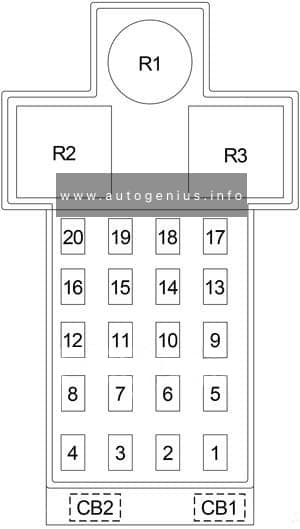
| Relay | ||
| R1 | Power Window | |
| R2 | Fuel Pump (PGM-FI Main 2) | |
| R3 | Starter Cut | |
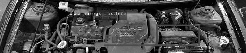
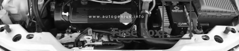
Engine Compartment
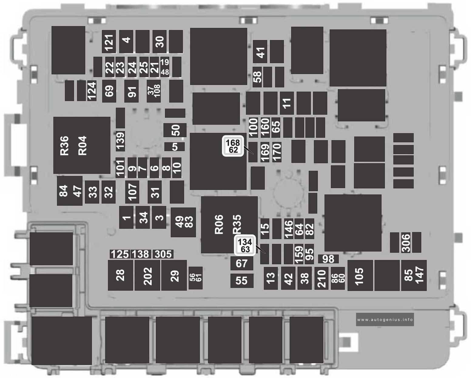
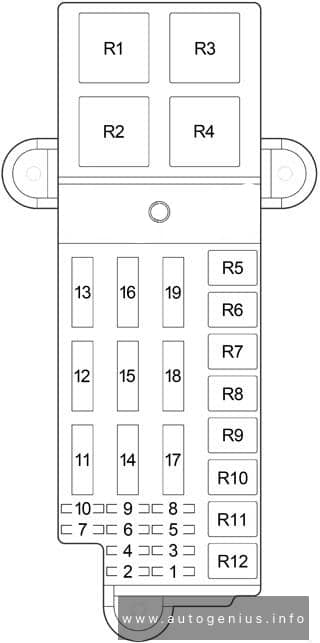
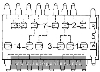
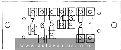
Fuse box diagram
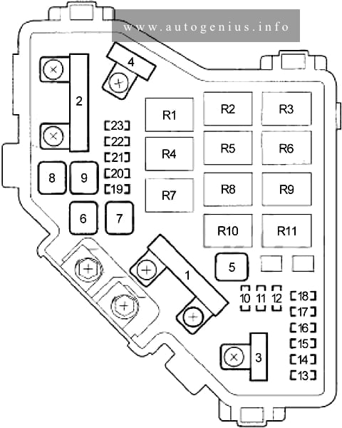
Assignment of the fuses in the engine compartment
| o. |
A |
Protected Component |
| 1 | 100 | Battery, Power Distribution |
| 70 | EPS Control Unit | |
| 2 | 50 | Ignition Switch |
| 80 | ’06-07: Fuses (Passenger Compartment): 5, 6, 7, 27, 28, 29, 31 | |
| 60 | ’08-’09: Fuses (Passenger Compartment): 5, 6, 7, 27, 28, 29, 31 | |
| 3 | 30 | ABS Modulator-Control Unit, VSA Modulator-Control Unit |
| 30 | ABS Modulator-control Unit | |
| 40 | VSA Modulator-control Unit | |
| 4 | 50 | Fuses (Passenger Compartment): 18, 19, 20, 21 |
| 40 | Fuses (Passenger Compartment): 24, 25, 26, 30, 32, 33 | |
| 5 | – | – |
| 6 | 20 | A/C Condenser Fan Motor |
| 7 | 20 | Radiator Fan Motor |
| 8 | 30 | Rear Window Defogger |
| 9 | 40 | Blower Motor |
| 10 | 10 | Hazard Lights |
| 11 | 15 | A/F Sensor (Sensor 1), ECM/PCM |
| 12 | 15 | Brake Lights, ECM/PCM, Horn, Multiplex Integrated Control Unit (MICU) |
| 13 | – | – |
| 14 | – | – |
| 15 | 7.5 | A/C Condenser Fan Relay |
| 16 | – | – |
| 17 | 15 | Stereo Amplifier |
| 18 | 15 | ECM/PCM, Ignition Coils |
| 19 | 15 | CKP Sensor, CMP Sensor B, ECM/PCM, ETCS Control Relay, Injectors, PGM-FI Main Relay 1 (Fl MAIN), PGM-FI Main Relay 2 (Fuel Pump) |
| 20 | 7.5 | A/C Compressor Clutch |
| 21 | 15 | ECM/PCM (ETCS Control Relay) |
| 22 | 7.5 | Ceiling Lights. Courtesy Light, Mao Lights, Trunk Lights |
| 23 | 10 | Audio Unit, Data Link Connector, Gauge Control Module (Tach), Gauge Control Module (Speedo), Hazard Warning Switch, Immobilizer-Keyless Control Unit, Multiplex Integrated Control Unit (MICU), HandsFreeLink Control Unit, Navigation Unit |
| Relay | ||
| R1 | Radiator Fan | |
| R2 | A/C Condenser Fan | |
| R3 | Fan Control | |
| R4 | Electronic Throttle Control System (ETCS) Control | |
| R5 | Blower Motor | |
| R6 | Power Mirror Defogger | |
| R7 | PGM-FI Main (No.1) | |
| R8 | Rear Window Defogger | |
| R9 | PGM-FI Sub | |
| R10 | A/C Compressor Clutch | |
| R11 | Ignition Coil | |
WARNING: Terminal and harness assignments for individual connectors will vary depending on vehicle equipment level, model, and market.