Volkswagen Golf IV (Type 1J; 1997 – 2003) – fuse box diagram
Year of production: 1997, 1998, 1999, 2000, 2001, 2002, 2003
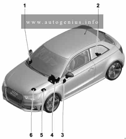
The 4rd generation Volkswagen Golf compact car was produced in 1997, 1998, 1999, 2000, 2001, 2002 and 2003 with gasoline and diesel engines. Delivered worldwide in various body styles: convertible, sedan, station wagon and hatchback. In this article you will find a designation of the fuse and relay boxes diagram of the 4th generation Volkswagen Golf.
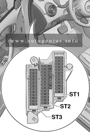
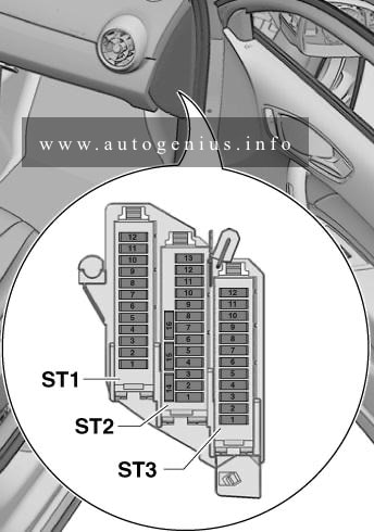
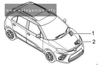
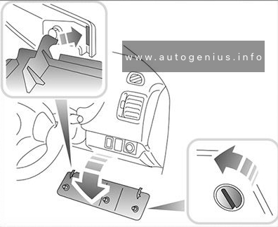
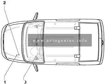
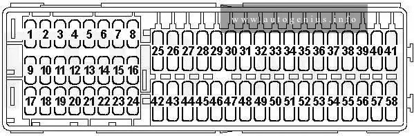
Passenger comartment
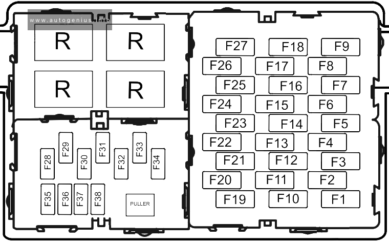
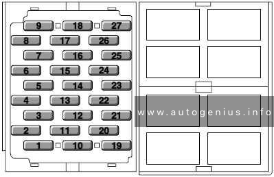
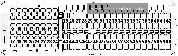
Fuse box diagram
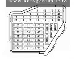
Assignment of the fuses in the passenger compartment
| № |
A |
Function/component |
| 1 | 5 | Z4 – Driver side heated exterior mirror (models without ohne electric window regulator) Z5 – Front passenger side heated exterior mirror (models without ohne electric window regulator) Z20 – Left washer jet heater element Z21 – Right washer jet heater element |
| 2 | 5 | E3 – Hazard warning light switch J1 – Turn signal relay M5 – Front left turn signal bulb M6 – Rear left turn signal bulb M7 – Front right turn signal bulb M8 – Rear right turn signal bulb J567 – Left gas discharge light control unit J568 – gas discharge light control unit with headlight range control right |
| 3 | 5 | J5 – Fog light relay E20 – Switches and instruments illumination regulator |
| 4 | 5 | X – Number plate lights |
| 5 | 7.5 | E45 – Cruise control system switch E221 – Operating unit in steering wheel E227 – Cruise control system button (CCS) SET button G65 – High pressure sender (air conditioning system) J131 – Heated driver seat control unit J132 – Heated front passenger seat control unit J245 – Sliding sunroof adjustment control unit (models without central locking) J255 – Climatronic G266 – Oil level and oil temperature sender J293 – Radiator fan control unit, multifunction steering wheel J393 – Convenience system (E231 – Exterior mirror heater button), J453 – Multifunction steering wheel control unit J446 – Parking aid control unit J503 – Control unit with display for radio and navigation system N147 – 2-way valve for coolant shut-off valve (above F269 – temperature flap position switch) V154 – Fresh air/recirculated air flap control motor |
| 6 | 55 | Up to April 2001: J379 – Central locking and anti-theft alarm system control unit from September 2002: J651 – Shut-off valve relay 1 (engine code BEH) |
| 7 | 10 | K142 – Selector lever position P/N warning lamp M16 – Left reversing light bulb M17 – Right reversing light bulb |
| 8 | 5 | J412 – Mobile telephone operating electronics control unit |
| 9 | 5 | E256 – TCS and ESP button G85 -Steering angle sender J104 – ABS/ABS control unit with EDL/ ASR/ ESP |
| 10 | 15 510 |
up to October 2001: Engine management: Petrol Engine management: Diesel from November 2001: R – Radio (S-contact) J285 – Display in dash panel insert J503 – Control unit with display for radio and navigation |
| 11 | 5 | J285 – Control unit with display in dash panel insert N110 – Selector lever lock solenoid |
| 12 | 7.5 | J412 – Mobile telephone operating electronics control unit G273 – Interior monitoring sensor G274 – Interior monitoring sender T16 – 16-pin connector, (in centre dash panel, self-diagnosis connection) W11 – Rear left reading light (models with interior monitor) W12 – Rear right reading light (models with interior monitor) |
| 13 | 10 | F – Brake light switch M9 – Left brake light bulb (only Golf/Bora) J…..-.Engine control units J104 – ABS/ABS control unit with EDL/ ASR/ ESP M9 – Left brake light bulb (only Golf/Bora) M10 – Right brake light bulb (only Golf/Bora) M21 – Left brake and tail light bulb (only Golf Variant/Bora Variant) M25 – High level brake light bulb |
| 14 | 10 | J393 – Convenience system central control unit (models without central lock) J546 – Rear lid remote release control unit models without central lock: M27 – Left door warning lamp M28 – Right door warning lamp W – Front interior light W3 – Luggage compartment light W11 – Rear left reading light W12- Rear right reading light W14 – Illuminated vanity mirror (front passenger side) W18 – Luggage compartment light on left W19 – Reading light/driver side W20 – Illuminated vanity mirror (driver side) |
| 15 | 5 | G85 – Steering angle sender J217 – Automatic gearbox control unit J285 – Control unit with display in dash panel insert |
| 16 | 10 | J255 – Climatronic J293 – Radiator fan control unit |
| 17 | – | – |
| 18 | 10 | J285 – Control unit with display in dash panel insert L2 – Right twin filament bulb (only Bora) M32 – Right main beam bulb (only Golf) |
| 19 | 10 | L1 – Left twin filament bulb (only Bora) M30 – Left headlight main beam bulb (only Golf) |
| 20 | 15 | E102 – Headlight range control regulator J427 – Right headlight starter for gaseous discharge light J568 – Gas discharge light control unit with headlight range control right L2 – Right twin filament bulb (only Bora) M31 – Right headlight dipped beam bulb (only Golf) V48 – Left headlight range control motor V49 – Right headlight range control motor |
| 21 | 15 | L1 – Left twin filament bulb (only Bora), M29 – Left headlight dipped beam bulb (only Golf) J426 – Left headlight starter for gaseous discharge light, J567 – Gas discharge light control unit with headlight range control left |
| 22 | 5 | J285 – Control unit with display in dash panel insert M3 – Right side light bulb |
| 23 | 5 | J285 – Control unit with display in dash panel insert M1 – Left side light bulb |
| 24 | 20 | E22 – Intermittent wiper switch, windscreen wiper motor J31 – Automatic intermittent wash and wipe relay V – Windscreen wiper motor V59 – Windscreen and rear window washer pump |
| 25 | 20 | E9 – Fresh air blower switch E35 – Air conditioning system switch N24 – Fresh air blower series resistor with overheating fuse V2 – Fresh air blower J293 – Radiator fan control unit J255 – Climatronic J… -Engine control units |
| 26 | 25 | Z1 – Heated rear window |
| 27 | 15 | up to November 2005: V12 – Rear window wiper motor from December 2005: U1 – Cigarette lighter U5 – 12 V socket, on left in luggage compartment |
| 28 | 15 | G6 – Fuel pump (pre-supply pump) |
| 29 | 15 2010 |
Petrol (not for engine code BDE) Engine management: Engine code BDEEngine management: Diesel |
| 30 | 20 | J245 – Sliding sunroof adjustment control unit V1 – Sliding sunroof motor |
| 31 | 20
5 |
J217 – Automatic gearbox control unit F125 – Multifunction switch J542 – Brake servo control unitJ492 – Four-wheel drive control unit (4 Motion) |
| 32 | 10 30 |
Injectors: Petrol Engine management: Diesel |
| 33 | 20 | J31 – Automatic intermittent wash and wipe relay V11 – Headlight washer system pump |
| 34 | 10 | Engine management |
| 35 | 30 | U10 – Trailer socket up to November 2005: U5-12 V socket, on left in luggage compartment |
| 36 | 15 | J5 – Fog light relay L22 – Left fog light bulb L23 – Right fog light bulb L46 – Rear left fog light bulb J285 – Control unit with display in dash panel insert |
| 37 | 15 510 |
up to October 2001: J285 – Control unit with display in dash panel insert J503 – Control unit with display for radio and navigation system R – Radio, S-contact from November 2001: Engine management: Petrol Engine management: Diesel |
| 38 | 15 | E204 – Tank filler flap remote release switch J379 – Central locking and anti-theft alarm system control unit J386 – Driver door control unit J387 – Front passenger door control unit J388 – Rear left door control unit J389 – Rear right door control unit J398 – Rear lid remote release relay V155- Tank filler flap locking motor |
| 39 | 15 | E3 – Hazard warning light switch J1 – Turn signal relay J567 – Gas discharge light control unit with headlight range control right J568 – Gas discharge light control unit with headlight range control right M5 – Front left turn signal bulb M6 – Rear left turn signal bulb M7 – Front right turn signal bulb M8 – Rear right turn signal bulb |
| 40 | 20 | H1 – Dual tone horn |
| 41 | 15 | U1-Cigarette lighter (up to November 2005) |
| 42 | 25 | R – Radio R12 – Amplifier J503 – Control unit with display for radio and navigation system J415 – Navigation system tuner for TV J559 – Traffic information control unit |
| 43 | 10 | Engine management |
| 44 | 15 | J131 -Heated driver seat control unit J132 -Heated front passenger seat control unit |
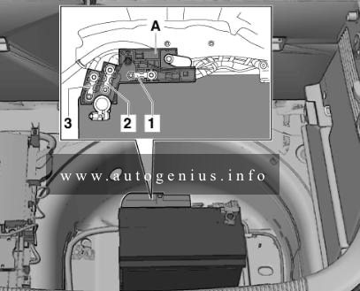
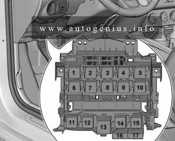
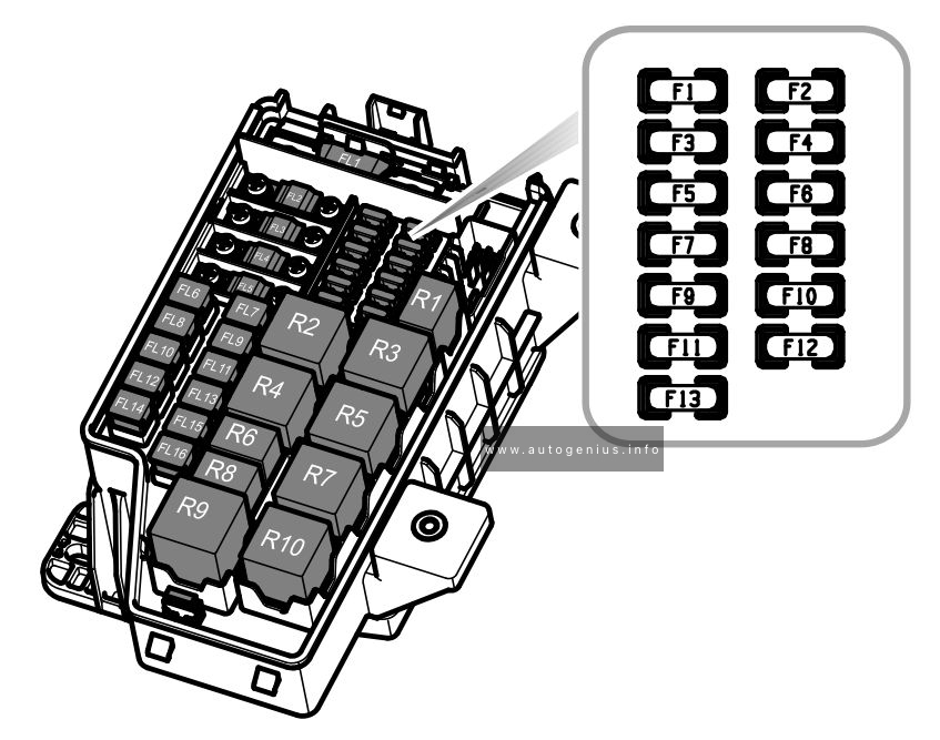
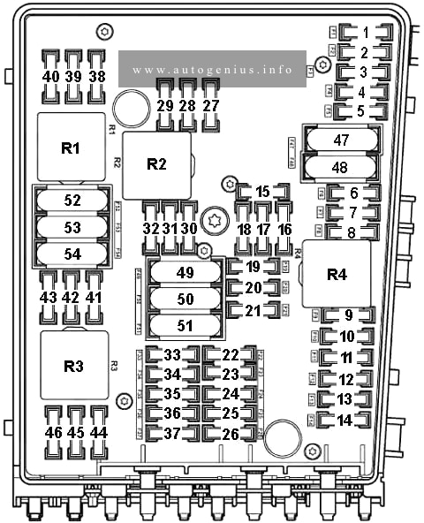
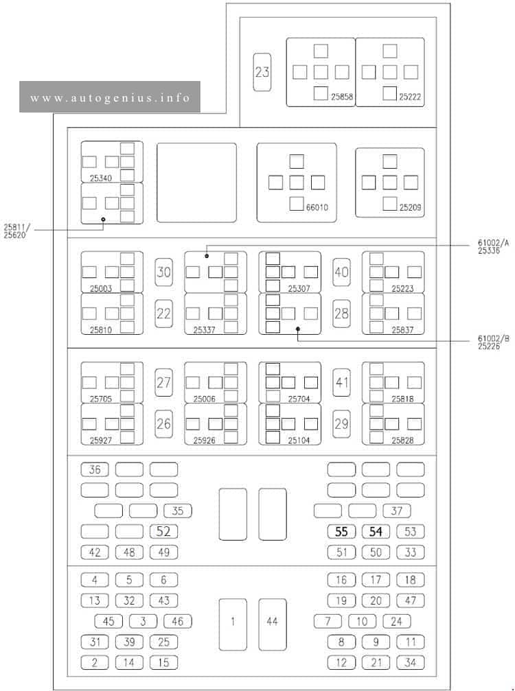
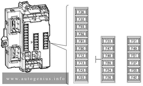
Engine compartment
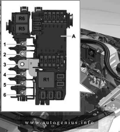
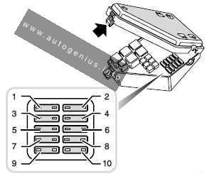
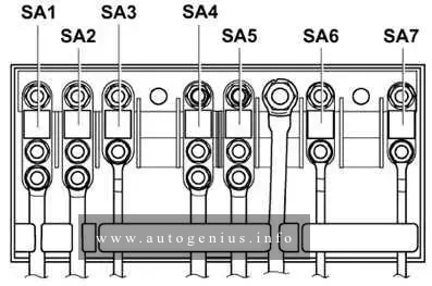
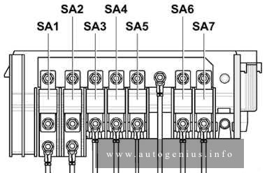
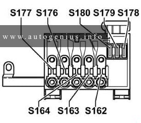
Position of fuses in fuse holder/battery
Up to August 2000
From September 2000
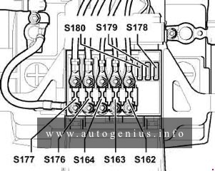
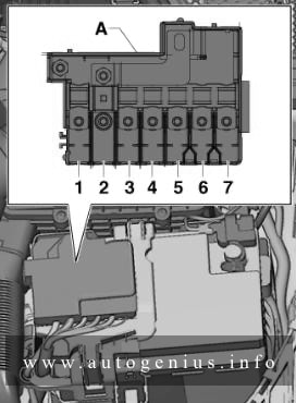
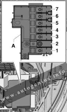
Assignment of the fuses in the engine compartment
| № |
A |
Function/component |
| S162 | 50 | Heated pin heating |
| S163 | 50 | Engine management |
| S164 | 40 | Radiator fan |
| S176 | 110 | Interior |
| S177 | 110 150 |
Alternator (90 A) Alternator (120 A) |
| S178 | 30 | ABS (pump) |
| S179 | 30 | ABS |
| S180 | 30 | Radiator fan |
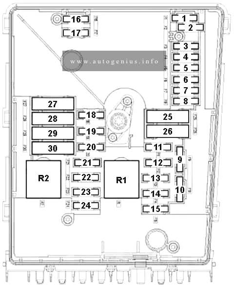
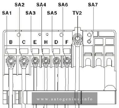
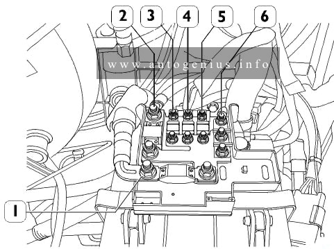
Position of relays and fuses
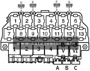
Assignment of the fuses and relays in the box
| Fuse locations on relay plate | ||
| A | – | Seat adjustment fuse |
| B | – | Fuses for V192 – Vacuum pump for brakes (from May 2002) |
| C | – | Window regulator fuse, central locking and heated exterior mirror (only models with convenience system and window regulator) |
| Relay positions on relay plate | ||
| 1 | J4 – Dual tone horn relay (53) | |
| 2 | J59 – X-contact relief relay (18) J59 – X-contact relief relay (100) | |
| 3 | Vacant | |
| 4 | J17 – Fuel pump relay (409) J52 – Glow plug relay (103) | |
| V/VI | J31 – Automatic intermittent wash and wipe relay, without headlight washer system (377), -with headlight washer system (389), -with rain sensor (192) | |
| Relay locations on the 13 position additional relay carrier above the relay plate, left-handdrive vehicles | ||
| 1 | Vacant | |
| 2 | J398 – Rear lid remote release relay (79) J546 – Rear lid remote release control unit (407) |
|
| 3 | Vacant | |
| 4 | J5 – Fog light relay (53) | |
| 5 | J453 – Multifunction steering wheel control unit (450) | |
| 6 | J453 – Multifunction steering wheel control unit (450) | |
| 7 | J508 – Brake light suppression relay (206) | |
| 8 | J99 – Heated exterior mirror relay (53) J541 – Coolant shut-off valve relay (53) |
|
| 9 | J17 – Fuel pump relay, four-wheel-diesel, (53) | |
| 10 | J17 – Fuel pump relay (pre-supply pump) (167) | |
| 11 | J226 – Starter inhibitor and reversing light relay (175) | |
| 12 | J317 – Terminal 30 voltage supply relay (109) | |
| 13 | J151 – Continued coolant circulation relay (53) | |
| Fuse locations on 13 position additional relay carrier, left-handdrive vehicles: | ||
| D | – | Vacant |
| E | – | Vacant |
| F | 15A | S30 – Rear window wiper single fuse (from December 2005), S144 – Anti-theft alarm system central locking fuse (ATA turn signal) |
| G | 15A | S111 – Anti-theft alarm system fuse (ATA horn) |
| 1 | J453 – Multifunction steering wheel control unit (450) | |
| 2 | J453 – Multifunction steering wheel control unit (450) | |
| 3 | J5 – Fog light relay (53) | |
| 4 | Vacant | |
| 5 | J398 – Rear lid remote release relay (79) J546 – Rear lid remote release control unit (407) |
|
| 6 | Vacant | |
| 7 | J151 – Continued coolant circulation relay (53) | |
| 8 | J317 – Terminal 30 voltage supply relay (109) | |
| 9 | J226 – Starter inhibitor and reversing light relay (175) | |
| 10 | J17 – Fuel pump relay (pre-supply pump) (167) | |
| 11 | J17 – Fuel pump relay, four-wheel-diesel, (53) | |
| 12 | J99 – Heated exterior mirror relay (53) J541 – Coolant shut-off valve relay (53) J193 – Cigarette lighter relay (53) |
|
| 13 | J508 – Brake light suppression relay (206) | |
| D | 15A | S144 – Anti-theft alarm system central locking fuse (ATA turn signal) |
| E | 15A | S111 – Anti-theft alarm system fuse (ATA horn) S30 – Rear window wiper single fuse (from December 2005) |
| F | – | Vacant |
| G | – | Vacant |
WARNING: Terminal and harness assignments for individual connectors will vary depending on vehicle equipment level, model, and market.