Mitsubishi Eclipse (2003 – 2005) – fuse and relay box diagram
Year of production: 2003, 2004, 2005
This article focuses on the post-facelift third-generation Mitsubishi Eclipse, produced from 2003 to 2005. It includes fuse box diagrams for the 2003, 2004, and 2005 models, provides the locations of the fuse panels within the vehicle, and explains the roles of each fuse and relay (fuse layout).
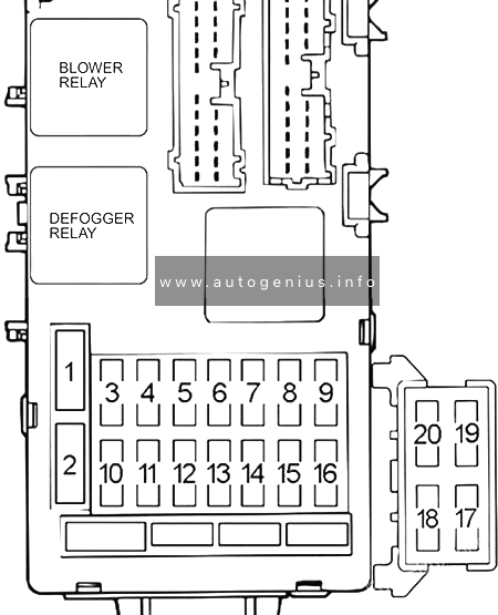
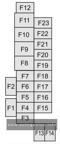
Passenger compartment fuse box
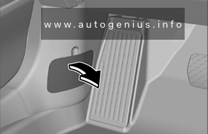
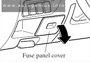
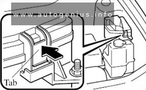
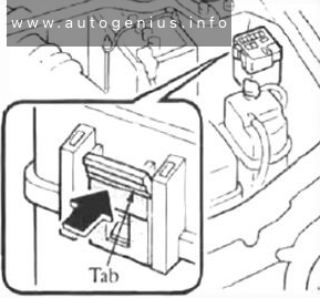
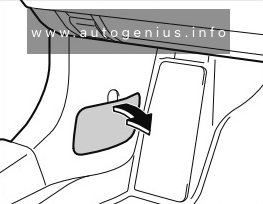
Fuse Box Location
The fuses are located behind the dashboard side cover on the driver’s side.
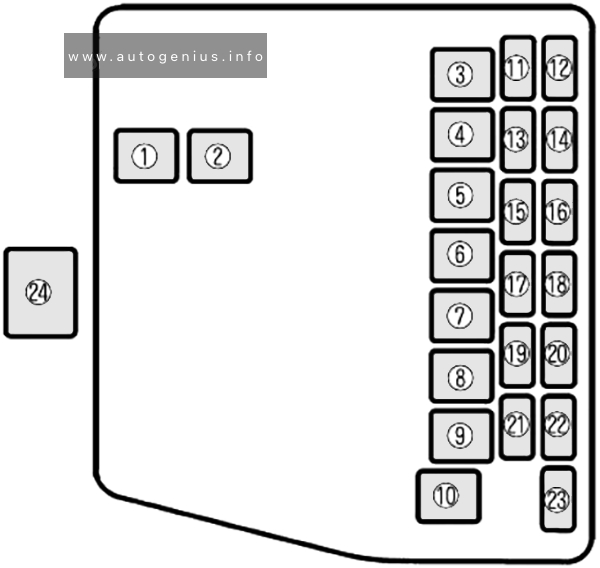
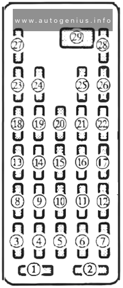
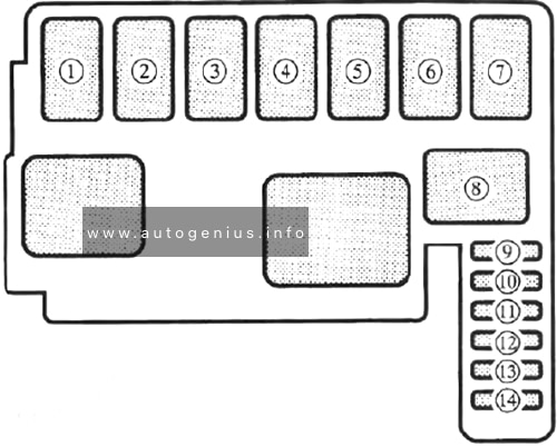
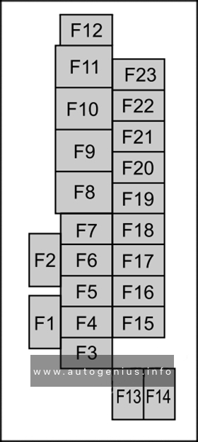
Fuse Box Diagram
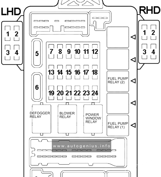
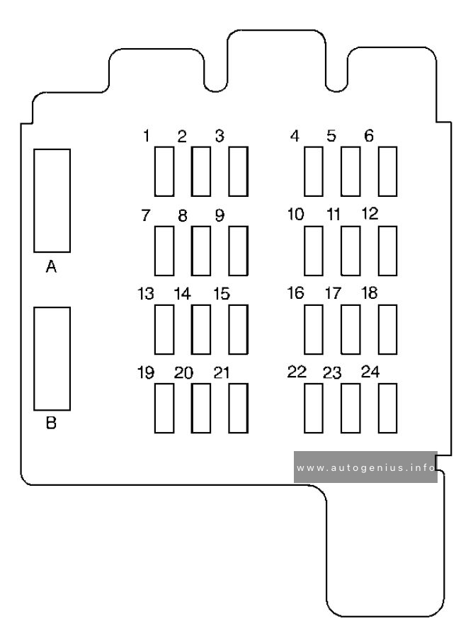
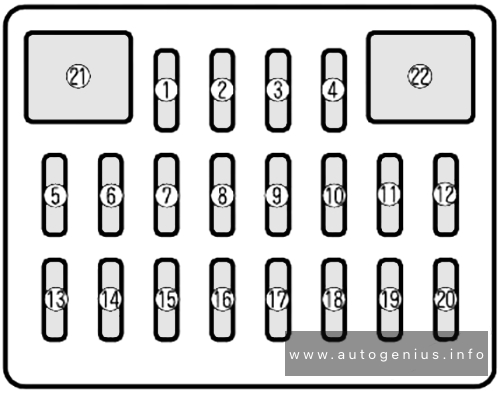
Assignment of the fuses in the passenger compartment
| № | Amps | Load Circuit |
|---|---|---|
| 1 | 20A | Amplifier |
| 2 | – | – |
| 3 | 20A | Sunroof motor assembly |
| 4 | – | – |
| 5 | 30A | Capacitor, choke coil and defogger |
| 6 | 30A | Automatic compressor controller, blower motor and resistor |
| 7 | – | – |
| 8 | – | – |
| 9 | – | – |
| 10 | 15A | Combination meter, data link connector and ETACS-ECU |
| 11 | 15A | Capacitor, ETACS-ECU and rear wiper motor |
| 12 | – | – |
| 13 | 7.5A | ABS-ECU, convertible top control module and sunroof motor assembly |
| 14 | 7.5A | Remote controlled mirror |
| 15 | – | – |
| 16 | 15A | Accessory socket, cigarette lighter and multi center display unit |
| 17 | 7.5A | Engine control module, fuel pump relay and powertrain control module |
| 18 | 20A | Front-ECU and windshield wiper motor |
| 19 | – | – |
| 20 | 7.5A | A/C compressor relay, A/C switch, automatic compressor controller, blower relay, defogger relay, front-ECU, outside/inside air selection damper control motor, water shut motor and water shut valve controller |
| 21 | 7.5A | Auto-cruise control-ECU and autocruise control switch |
| 22 | 7.5A | Backup light, combination meter, ETACS-ECU, input shaft speed sensor, output shaft speed sensor, powertrain control module and SRS-ECU |
| 23 | 7.5A | Column switch, combination meter, ETACS-ECU, motor antenna assembly, multi center display unit, SRS-ECU and vehicle speed sensor |
| 24 | 10A | Capacitor, distributor assembly and ignition coil |
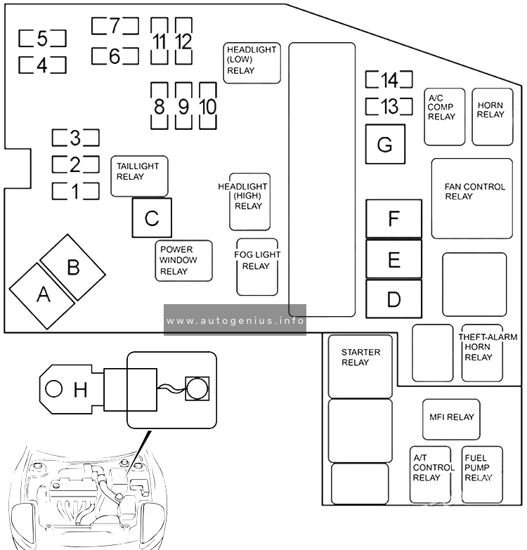
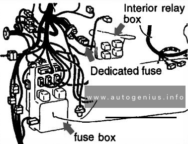
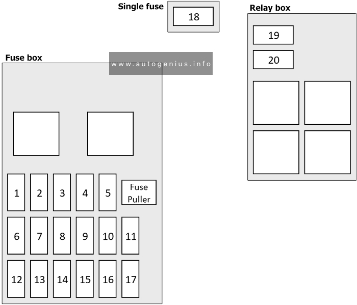
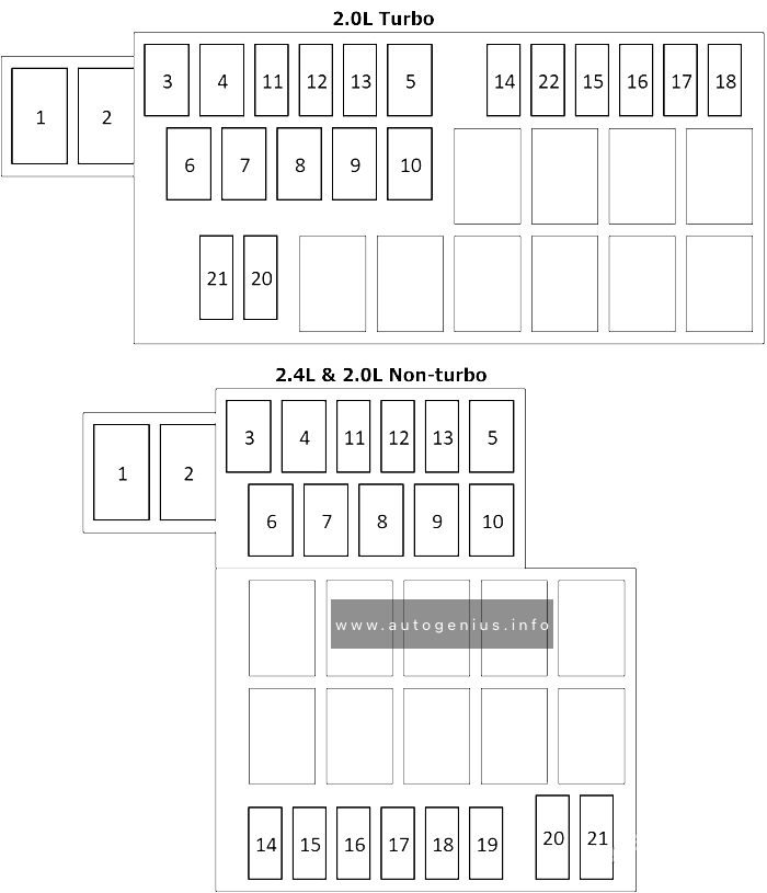
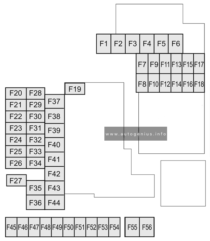
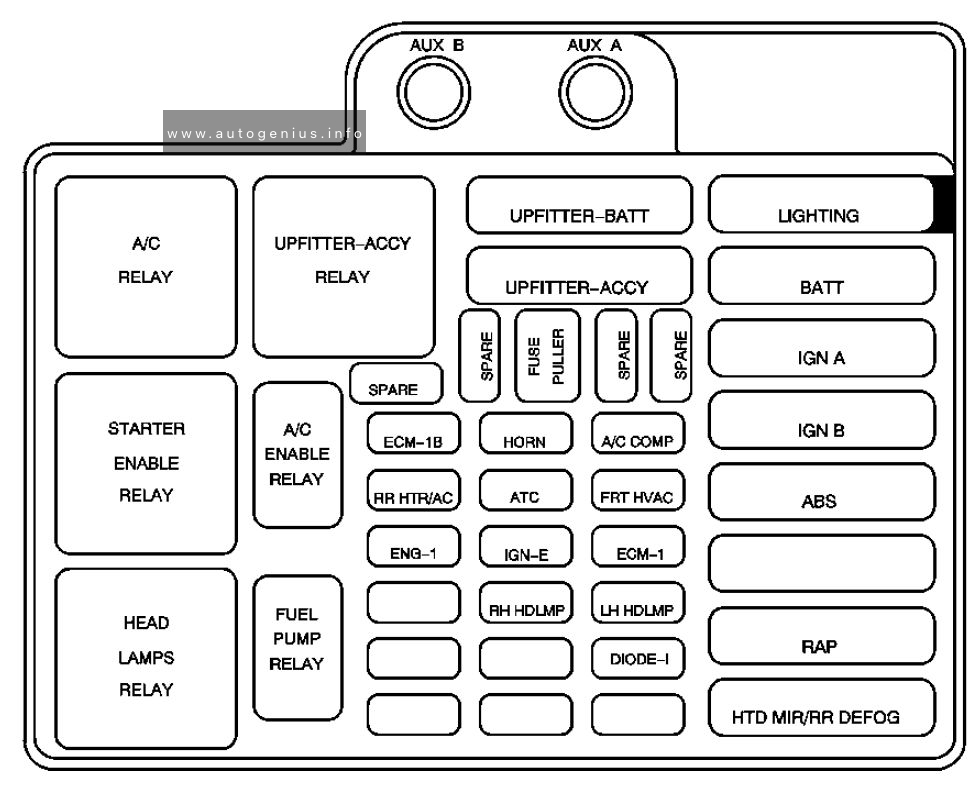
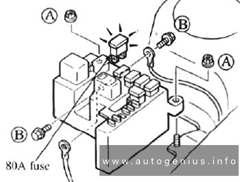
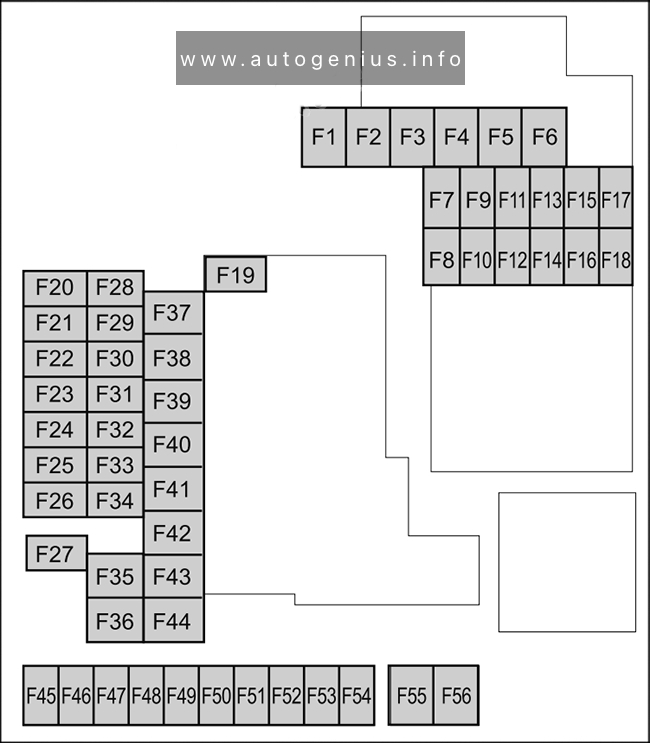
Engine compartment fuse box
Fuse Box Diagram
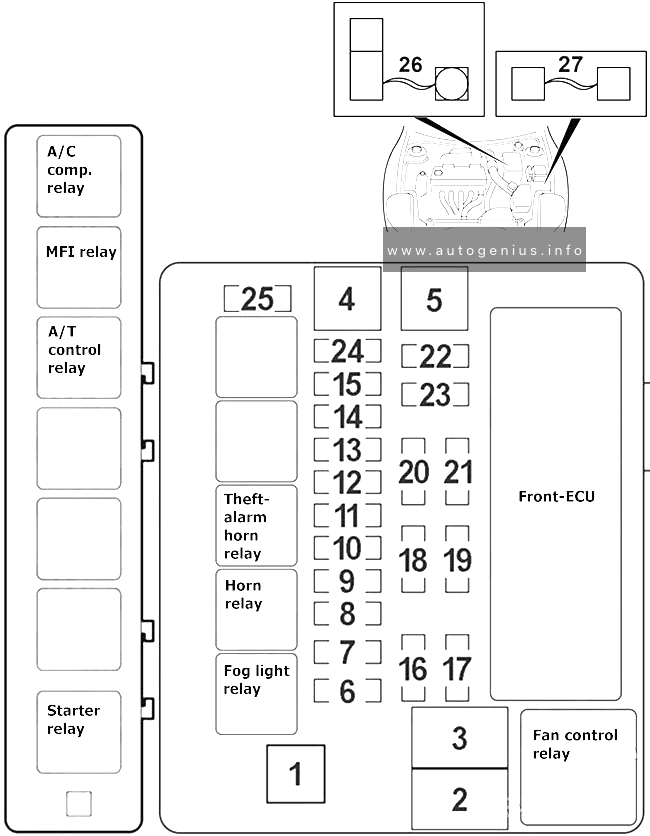
Assignment of the fuses in the engine compartment
| № | Amps | Load Circuit |
|---|---|---|
| 1 | 60A | Fuses №5, 6, 10 (in junction block) circuit |
| 2 | 50A | Fan controller |
| 3 | 60A | ABS-ECU |
| 4 | 40A | Ignition switch circuit, theft-alarm horn and theft-alarm horn relay |
| 5 | 30A | Fuses №1, 3 (injunction block) circuit, convertible top control module, power seat assembly, power window main switch and power window motor |
| 6 | 15A | Combination meter and fog light |
| 7 | – | – |
| 8 | 15A | Horn and horn relay |
| 9 | 20A | Camshaft position sensor, crankshaft position sensor, distributor assembly, EGR solenoid valve, engine control module, evaporative emission purge solenoid, evaporative emission ventilation solenoid, heated oxygen sensor, idle air control motor, immobilizer-ECU, injector, MFI relay, powertrain control module, variable induction control solenoid valve and volume air flow sensor |
| 10 | 10A | A/C compressor assembly and automatic compressor controller |
| 11 | 15A | ABS-ECU, auto-cruise control-ECU, capacitor, high-mounted stoplight, immobilizer-ECU, powertrain control module and rear combination light |
| 12 | – | – |
| 13 | 7.5A | Generator |
| 14 | 10A | ETACS-ECU |
| 15 | 20A | A/T control solenoid valve assembly and powertrain control module |
| 16 | 10A | Headlight (RH) |
| 17 | 10A | Headlight (LH) |
| 18 | 10A | Headlight (RH) |
| 19 | 10A | Headlight (LH) |
| 20 | 7.5A | A/C switch, A/T selector lever position illumination light, ashtray illumination light, automatic compressor controller, combination meter, fog light switch, front combination light (RH), glove box light, hazard warning light switch, heater control panel illumination light, multi center display unit, radio, tape player, CD player, rear combination light (RH), rear side marker light (RH) and rheostat |
| 21 | 7.5A | Front combination light (LH), license plate light, rear combination light (LH) and rear side marker light (LH) |
| 22 | 10A | Column switch, combination meter, ETACS-ECU, front-ECU, motor antenna assembly, multi center display unit, radio, tape player, CD player, sunroof motor assembly and vanity mirror light |
| 23 | 10A | ETACS-ECU, motor antenna assembly, radio, tape player and CD player |
| 24 | 15A | Fuel pump module |
| 25 | – | – |
| 26 | 120A | Generator (The fusible link is connected to battery positive terminal) |
| 27 | 30A | Convertible top control module (The fusible link is connected in front of the relay box) |
WARNING: Terminal and harness assignments for individual connectors will vary depending on vehicle equipment level, model, and market.