Lincoln Navigator (UN173; 1998) – fuse and realy box diagram

Lincoln Navigator (UN173; 1998) – fuse and relay  box diagram

Year of production: 1998


This article covers the first-generation Lincoln Navigator, manufactured between 1998 and 2002. It includes fuse box diagrams for the 1998 models, provides details on the locations of the fuse panels within the vehicle, and explains the function and layout of each fuse and relay.

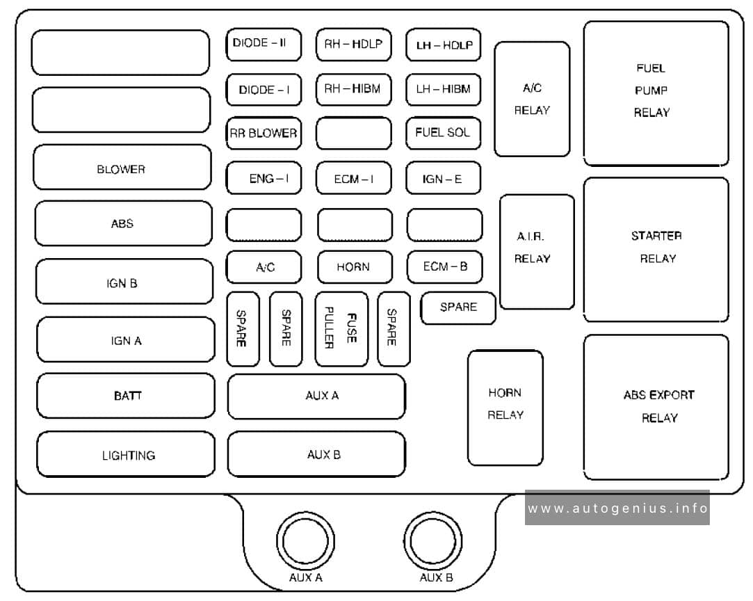
Engine compartment fuse panel
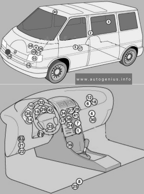
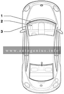
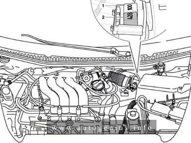
Fuse box location

The power distribution box is located in the engine compartment (on the driver’s side).
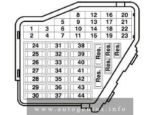
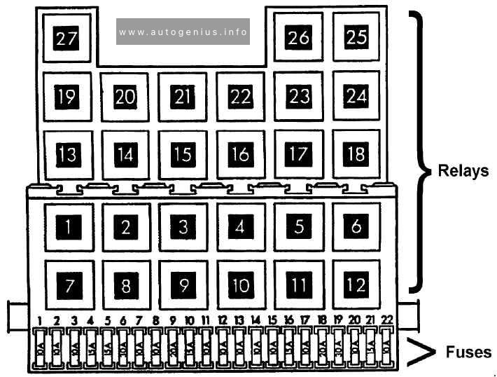
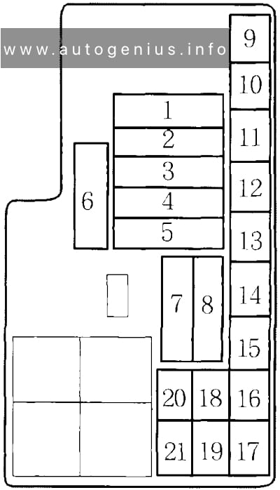
 

Fuse box diagram

Lincoln Navigator (UN173; 1998) - fuse and relay box diagram - engine compartment
Lincoln Navigator (UN173; 1998) – fuse and relay box diagram – engine compartment


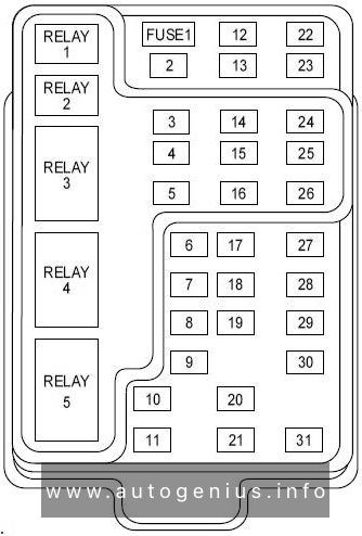
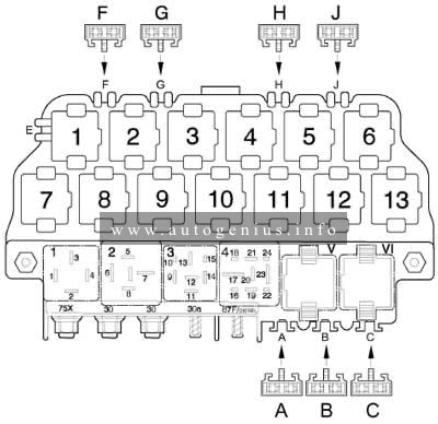
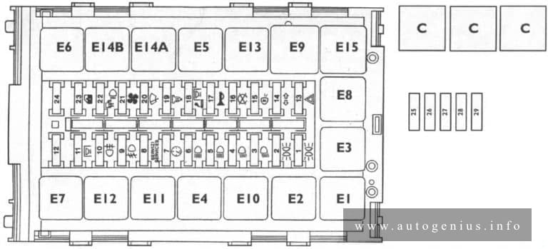
Assignment of the fuses and relays in the engine compartment (1998)

No.
A
Circuit Protected
1 15A Flasher Relay
2 5A Instrument Cluster, Overhead Trip Computer (OTC) Module, Redundant Steering Control Module, Electronic Automatic Temperature Control (EATC) Module, Clock
3 25A Cigar Lighter
4 5A Park Lamp Relay, Headlamp Relay, Autolamp Module, Remote Anti-theft Personality (RAP) Module, Power Mirror Switch, Memory Seat and Mirror Module, Driver Power Seat Control Switch, Memory Seat Switch
5 15A Digital Transmission Range (DTR) Sensor, Daytime Running Lamps (DRL) Module, Speed Control Servo/Amplifier Assembly, EATC Clutch Relay
6 5A Shift Lock Actuator, Generic Electronic Module (GEM), 4 Wheel Air Suspension 4WAS Module, Compass Sensor, Steering Wheel Rotation Sensor, Heated Grid Relay, Overhead Trip Computer (OTC) Module
7 5A Auxiliary A/C Relay, Console Blower Motor
8 5A Radio, Main Light Switch, Remote Anti-theft Personality (RAP) Module, Generic Electronic Module (GEM), Ignition Switch, Clock
9 Not used
10 Not used
11 30A Washer Pump Relay, Wiper Run/Park Relay
12 5A Data Link Connector (DLC)
13 15A Brake On/Off (BOO) Switch, Brake Pressure Switch
14 15A Battery Saver Relay, Interior Lamp Relay
15 5A Generic Electronic Module (GEM), SecuriLock
16 20A Instrument Cluster (W/O DRL), Daytime Running Lamps (DRL) Module, Hi-Beam Headlamps (Power supplied through Multi-Function Switch)
17 10A Heated Backlite Switch, Left Power/Heated Signal Mirror, Right Power/Heated Signal Mirror
18 5A Main Light Switch, Generic Electronic Module (GEM), Instrument Illumination, (Power supplied through Main Light Switch), Park Lamp Relay, Trailer Electronic Brake Control, Trailer Tow Running Lamp Relay, Left Side Marker Lamps, Right Side Marker Lamps, Left Front Park/Turn Lamp, Right Front Park/Turn Lamp, Left Stop/Park/Tum Lamp, Right Stop/Park/Tum Lamp, Left License Lamp, Right License Lamp
19 10A Instrument Cluster, Air Bag Diagnostic Monitor
20 5A 4 Wheel Air Suspension 4WAS Generic Electronic Module (GEM), Memory Seat and Mirror Module
21 15A Digital Transmission Range (DTR) Sensor, Junction Box Fuse/Relay Panel (Fuse 20)
22 10A Air Bag Diagnostic Monitor, Ignition Swatch
23 10A Trailer Tow Battery Charge Relay, 4X4 Center Axle Disconnect Solenoid, 4X2 Center Axle Disconnect Solenoid, Electronic Day/Night Mirror, Rear Integrated Control Panel, Auxiliary A/C Mode Actuator, Auxiliary A/C Control Module, Auxiliary A/C Blend Actuator Flasher Relay
24 10A Electronic Automatic Temperature Control (EATC) Module, Console Blower Relay, Auxiliary A/C Relay
25 5A 4 Wheel Anti-Lock Brake System (4WABS) Module 4WABS Relay
26 10A Daytime Running Lamps (DRL) Module, Right Headlamp (Powder supplied through Multi-Function Swatch)
27 5A Main Light Swatch, Fog Lamp Relay
28 10A Left Headlamp
29 5A Autolamp Module, Instrument Cluster, Transmission Control Swatch (TCS)
30 30A Radio Noise Capacitor, PCM Power Diode, Coil on Plugs, PCM Powder Relay, SecuriLock
31 Not Used
31 10 Rear Integrated Control Panel (Audio), CD Player, Cell Phone

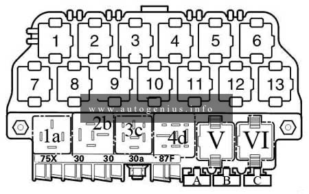
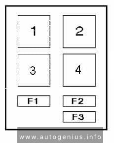
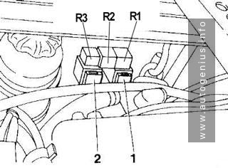
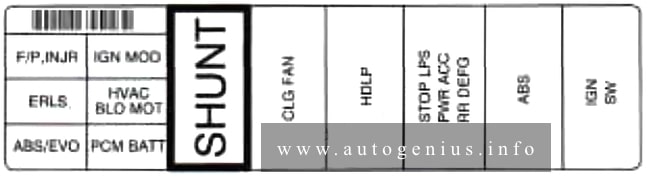
Engine Compartment Fuse Box
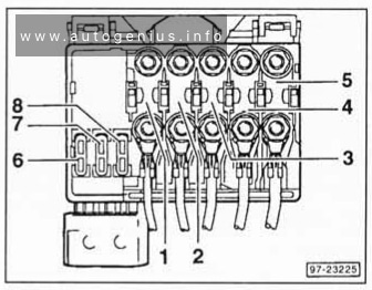
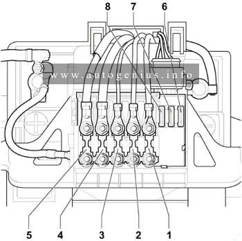
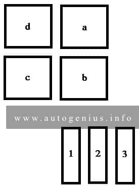
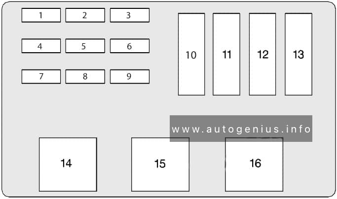
Power fuse box

Lincoln Navigator (UN173; 1998) - fuse and relay box diagram - passenger compartment (power fuse box)
Lincoln Navigator (UN173; 1998) – fuse and relay box diagram – passenger compartment (power fuse box)


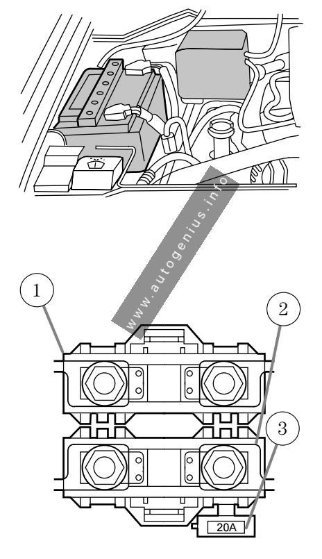
Assignment of the fuses and relays in the power fuse box (1998)

Location Amperage Description
1 175 Power Network Box Megafuse
2 175 Alternator Megafuse
3 20 Alternator Field Minifuse

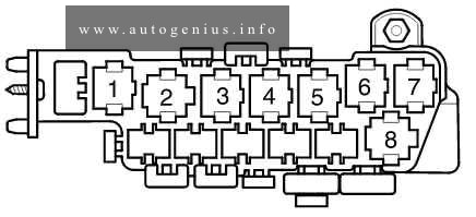
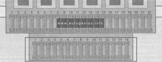
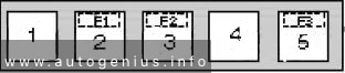
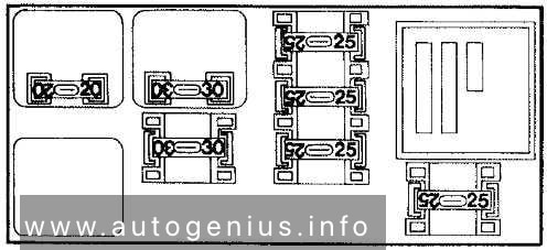
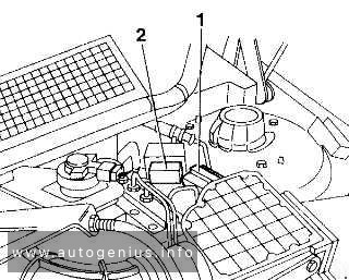
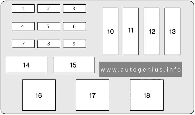
Additional fuse panel

Lincoln Navigator (UN173; 1998) - fuse and relay box diagram - passenger compartment (engine mini fuse box)
Lincoln Navigator (UN173; 1998) – fuse and relay box diagram – passenger compartment (engine mini fuse box)


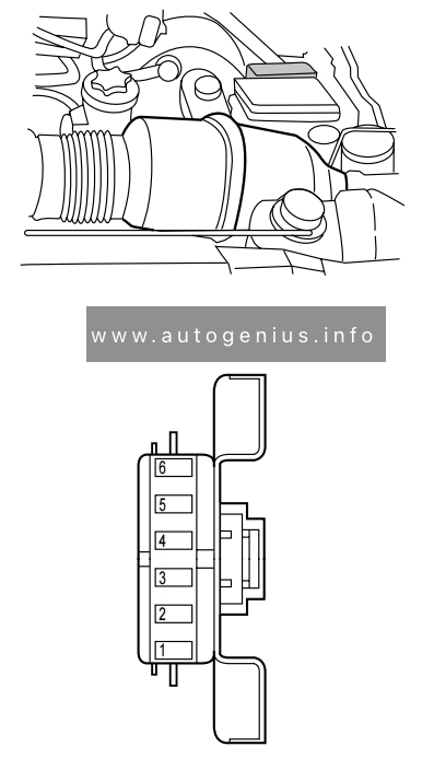
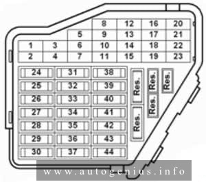
Assignment of the fuses and relays in the additional fuse panel (1998)

Slot number Ampere rating [A] Circuit protected
1 5 Powertrain Control Module (PCM)
2 20 Trailer Tow Stop/Turn Lamps
3 10 Audio Rear Integrated Control Panel (RICP), Compact Disc Changer, Radio
4 10 Running Board Lamps
5 20 Amplifier, Subwoofer Amplifier
6 Not used


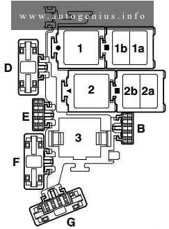
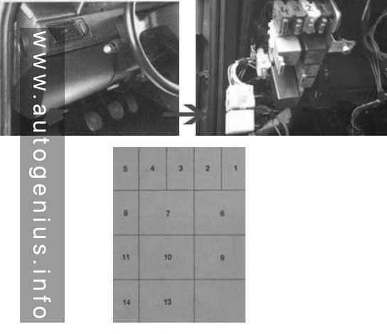
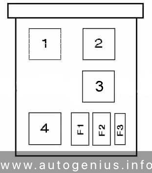
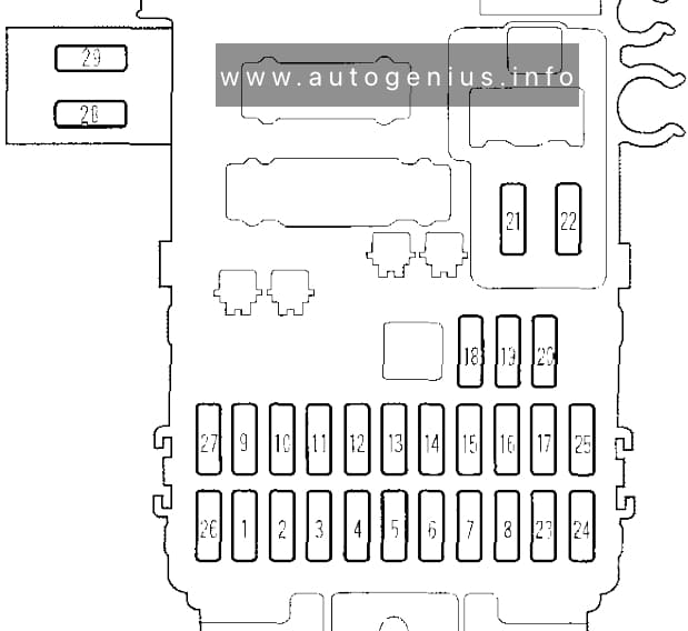
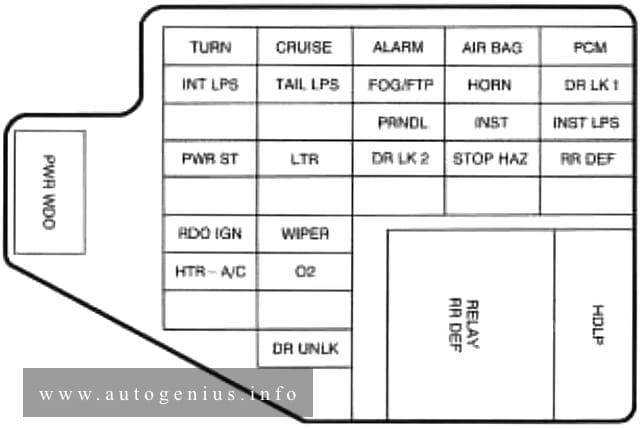
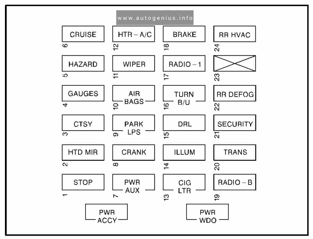
Passenger compartment box
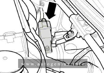
Fuse box location

The fuse panel is located below and to the left of the steering wheel behind the cover.
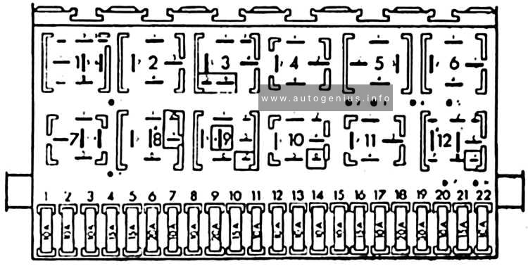
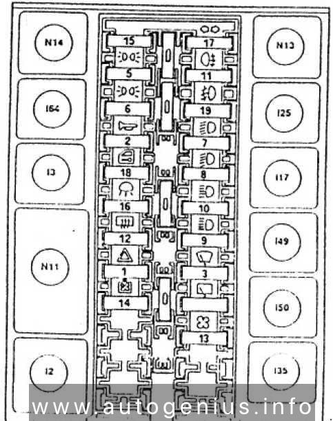
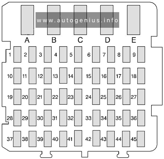
 

Fuse box diagram

Lincoln Navigator (UN173; 1998) - fuse and relay box diagram - passenger compartment
Lincoln Navigator (UN173; 1998) – fuse and relay box diagram – passenger compartment


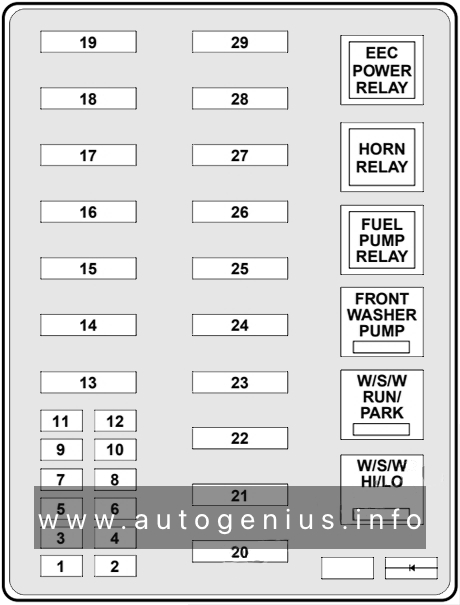
Assignment of the fuses and relays in the passenger compartment (1998)

Amp Rating Description
1 20A Trailer Tow Running Lamp Relay, Trailer Tow Backup Lamp Relay
2 10A Air Bag Diagnostic monitor
3 30A All Unlock Relay, All Lock Relay, Driver’s Unlock Relay
4 15A Air Suspension Sendee Switch
5 20A Horn Relay
6 30A Radio, Premium Sound Amplifier, CD Changer, Rear Integrated Control Panel, Sub-Woofer power
7 15A Main Light Switch, Park Lamp Relay
8 30A Main Light Switch, Headlamp Relay, Multi-Function Switch
9 15A Daytime running lamps (DRL) Module, Fog Lamp Relay
10 25A I/P Auxiliary Power Socket
11 25A Console Auxiliary Power Socket
12 10A Rear Wiper Up Motor Relay, Rear Wiper Down Motor Relay
13 30A Auxiliary A/C Relay
14 60A 4 Wheel Anti-Lock Brake System (4WABS) Module
15 50A Air Suspension Solid State Compressor Relay
16 40A Trailer tow battery Charge Relay, Mini Fuse Block (fuse 2), Trailer Tow Right Turn Relay, Trailer tow Left Turn Relay
17 30A Transfer Case Shift Relay, Torque on Demand Relay
18 30A Memory Seat Module
19 20A Fuel Pump Relay
20 50A Ignition Switch
21 50A Ignition Switch
22 50A Junction Box Fuse/Relay Panel Battery Feed
23 40A I/P Blower Relay
24 30A PCM Power Relay, Mini Fuse Block (fuse 1), Powertrain Control Module
25 30A (CB) Junction Box Fuse/Relay Panel, ACC Delay Relay
26 30A Passenger Power Seat Control Switch
27 40A Junction Box Fuse/Relay Panel, Heated Grid Relay
28 30A Trailer Electronic Brake Control
29 30A RPO Relay Block, Vent Window/Moonroof Relay


WARNING: Terminal and harness assignments for individual connectors will vary depending on vehicle equipment level, model, and market.

Volkswagen Transporter (T4; 1990 – 2003) – fuse box diagram

Volkswagen Transporter (T4; 1990 – 2003) – fuse box diagram

Year of production: 1990, 1991, 1992, 1993, 1994, 1995, 1996, 1997, 1998, 1999, 2000, 2001, 2002, 2003


Volkswagen Transporter T4  – represents the 4th generation of the legendary Transporter series. This model was produced in 1990, 1991, 1992, 1993, 1994, 1995, 1996, 1997, 1998, 1999, 2000, 2001, 2002 and 2003 with diesel and gasoline engines with different wheelbases: short and long, and with different roof height. Also on the T4, Volkswagen continued its lineup of luxury Caravelle, California and Multivan models. In this article, we will show the location of all electronic control sides and a detailed designation of the purpose of fuses and relays Volkswagen T4 with box diagrams in which they are located.


Locations

Volkswagen Transporter T4 (1990 - 2003) - fuse box location
Volkswagen Transporter T4 (1990 – 2003) – fuse box location


1 Air conditioning control unit 1 – with automatic temperature control – in the heater control panel, front
2 Air conditioning control unit 2 – with automatic temperature control – in the heater control panel, rear – central pillar
3 Evaporator Fan Control Unit (A / C) – With Rear A / C – Behind Right Rear Trim Panel
4 Air conditioning / heater fan motor control unit 1 – with automatic temperature control – front – fan unit
5 Air conditioning / heater blower motor control unit 2- with automatic temperature control – rear- bottom of the body, in the center
6 Aerial amplifier – behind the dash, passenger side
7 Alternator resistor – near additional relays – CV / AUF, with alternator 150A / automatic transmission / automatic temperature control – behind the central part of the dashboard
8 Additional battery – under the driver’s seat
9 Accumulator battery
10 Central locking signal control unit – behind the dashboard
11 Cruise control unit (with throttle motor) – cruise control is controlled by the ECM
12 Electronic cruise control module (without throttle motor) – behind dash, passenger side
13 Diagnostic connector (DLC) – instrument panel, driver’s side
14 Diagnostic unit – 05/99 (except for AAC / ABL / AET / AES / AJA) – in the instrument cluster
15 Cooling Fan Motor Relay – Behind Left Headlight
16 Cooling Fan Motor 1/2 Resistor – Behind Left Headlight
17 Coolant heater control unit (with additional coolant heater – D3W / B4W / D4W) – in the heater – underbody, in the center
18 Coolant heater control unit (with optional coolant heater – B7W / D7W) – behind the dash, passenger side
19 Engine oil pressure warning buzzer – in instrument cluster control unit
21 Fuse / relay box, instrument cluster 1
22 Fuse / relay box 2, dash – under dash fuse / relay box 1
23 Fuse / relay box, dash 3 – above dash fuse / relay box 1
24 Fuse / relay box, dash 4 – behind dash, center
25 Fuse / Relay Box, Driver’s Seat – Under Seat
26 Fuse / Relay Box, Engine Compartment – Battery Powered
27 Additional fuse (5A / 7.5A / 10A) – in the back of the audio system unit
28 Additional fuse (10A) – at the rear of the navigation system control unit
29 Headlights not switched off warning buzzer – in the instrument cluster control unit
30 Heater blower motor resistor – manual temperature control – blower unit, front
31 Horn 1/2 – behind the front bumper
32 Immobilizer control unit – behind the instrument cluster
33 Immobilizer ring antenna – near the ignition switch
34 Turn signal relay, alarm relay – in the alarm switch
35 Instrument Cluster Control Module / Digital Multifunction Display – In Instrument Cluster
36 Outside temperature sensor – behind the front bumper
37 Driver’s seat heating control unit – in the seat heating switch
38 Passenger seat heating control unit – in the seat heating switch
39 SRS control unit – under the dash, center
40 Sunroof electric control unit
41 Theme control unit – in the display of the navigation system
42 Telephone interface control unit – behind the instrument cluster
43 Electronic gearbox control unit – near the engine control unit
44 Vehicle speed sensor – gearbox


Passenger compartment

Fuse box location

The main fuse and relay box is located under the dash on the driver’s side.

Fuse box diagram

Version 1

Volkswagen Transporter T4 (1990 - 2003) - fuse box diagram - passenger compartment (version 1)
Volkswagen Transporter T4 (1990 – 2003) – fuse box diagram – passenger compartment (version 1)

A
Description
1 10 Left Headlight Low Beam
2 10 Right Headlight Low Beam
3 10 Instrument & License Lights
4 15 Rear Window Wiper/Washer, Heated Front Seats
5 15 Windshield Wiper/Washer, Rear Window Washer, Heated Washer Jets
6 30 A/C, Fresh Air Fan
7 10 Right Tail Light & Side Marker Light, Engine Compartment Lamp
8 10 Left Taillight & Side Marker Light
9 20 Rear Window & Mirror Heater
10 15 Fog Lamps
11 10 Left Headlight High Beam & High Beam Indicator
12 10 Right Headlight High Beam
13 10 Horn, Radiator Cooling Fan
14 10 Backup Lights, Electric Mirrors, Heated Front Seats, Windshield Washer Jets, Cruise Control, Power Roof
15 10 Engine Electronics
16 15 Warning/Indicator Lights, Multi-Function Indicator, Glove Box Light, ABS
17 10 Turn Signals
18 20 Fuel Pump
19 30 A/C, Radiator Cooling Fan
20 10 Brake Lights
21 15 Dome & Luggage Lamps, Clock, Radio, Central Locking System, Multi-Function Indicator, Vanity Mirror, OBD Diagnostic
22 10 Cigarette Lighter
Relay
1 A/C Control Module Relay
2 Rear Window Wiper/Washer Relay
3 ECM Power Supply Relay
4 Load Reduction Relay
5 Open
6 Emergency Flasher Relay
7 Headlight Washer Relay
8 Washer/Wiper Intermittent Relay
9 Seat Belt Warning Relay
10 Fog Lamp/Parking Lamp Relay
11 Dual Horn Relay
12 Fuel Pump Relay
13 Heater Control Module Relay
14 Coolant Pump After-Run Relay
15 Open
16 Open
17 Open
18 Roof Ventilator Fan (Fuse)
19 Heater Air Blower Relay
20 Starter Interlock/Back-up Light Relay
21 5 Back-up Lights, Cruise Control
22 20 A/C (Second Evaporator)
23 Rear Window Defroster/Heated Mirror Relay
24 20 Power Windows, Central Locking System
25 10 ABS System
26 15 Rear Window Defroster, Heated Mirrors
27 A/C Compressor Clutch Relay

Version 2

Fuse box diagram (main box)

Volkswagen Transporter T4 (1990 - 2003) - fuse box diagram - passenger compartment (version 2)
Volkswagen Transporter T4 (1990 – 2003) – fuse box diagram – passenger compartment (version 2)

A
Description
Relay assignment
1 (105) Heater blower motor relay – rear (ventilation)
2 (174) Rear window wiper / washer relay
3 (30/109) Engine management relay
4 (18) Ignition auxiliary circuits relay 1
5 Reserve
6 (22/21) Emergency ventilation relay (with repeaters for direction indicators on the roof)
7 (95) Headlight washer pump relay
8 (99) Relay for intermittent operation of the windshield wiper / washer
9 (36) Headlamps warning buzzer
10 (53) Fog lamp relay
11 (53) Horn relay
12 (167) Fuel pump relay
Fuse
1 10 Left headlight – low beam, headlight range control
2 10 Right headlight – low beam, headlight range control
3 10 License plate lamps
4 15 Rear window wiper / washer, auxiliary ignition circuit relay 2, additional equipment
5 15 Windshield wiper / washer, heaters for windshield washer nozzles (05/01)
6 30 Air conditioning system, heater fan motor
7 10 Front right side / rear right side lamps
8 10 Lamps front left / rear left
9 20 Heated rear window, heated outside mirror
10 15 Fog lights
11 10 Left headlamp-high beam
12 10 RH headlamp-high beam
13 10 Sound signal
14 10 ABS system (with ESP), automatic transmission control system, additional equipment, central locking, cruise control system, power windows, power rear-view mirrors on the doors, reverse light (s)
15 10 Engine management system, crankcase ventilation heater, cruise control system, vehicle speed sensor
16 15 ABS indicator, glove box illumination lamp, turn signals, immobilizer, instrument cluster
17 10 Additional heater
18 20 Engine management system, fuel pump
19 30 A/C, Radiator Cooling Fan
20 10 Stop lights
21 15 Audio system, diagnostic connector (DLC), interior lamps, navigation system

Additional Fuse box

It is located under the main block.

Volkswagen Transporter T4 (1990 - 2003) - fuse box diagram - additional fuse box
Volkswagen Transporter T4 (1990 – 2003) – fuse box diagram – additional fuse box

A
Description
1 15 Accessory power connector
2 15 Trailer electrical connector
3 10 Roof identification light
4 20 Additional heater (AC V / AH Y / AJT / AU F)
5 10 Anti-lock braking system (ABS)
6 FOR Phone
7 15 Taxi
8 10 Roof fan
9 15 Audio system, instrument cluster
10 15 Central locking
11 15 Heated seats
12 30 Heated door mirrors, heated rear window
13 FOR PHONE (ACV / AH Y / AJT / AU F)
14 30 Air conditioning system – manual automatic temperature control
15 20 Additional heater


Additional relay box 1

Located at the top of the main unit.

Relay box diagram

Volkswagen Transporter T4 (1990 - 2003) - fuse box diagram - additional relay box no. 1
Volkswagen Transporter T4 (1990 – 2003) – fuse box diagram – additional relay box no. 1

  Description
1 (53) Coolant pump relay
2 (125) Idle speed control (AM) relay
3 (137) Glow plug control unit (ABL)
4 (53) Ignition auxiliary circuits relay 2 (some models)
5 (53) Ignition auxiliary circuits relay 2 (AES, with air conditioning)
F1 30 Power window fuse
F2 15 Engine control unit
F3 15 Actuator

Additional relay box 2

It is located behind the dashboard in the center.

Fuse box diagram

Volkswagen Transporter T4 (1990 - 2003) - fuse box diagram - additional relay box no. 2
Volkswagen Transporter T4 (1990 – 2003) – fuse box diagram – additional relay box no. 2

 Description
1 (106) Auxiliary heater relay
2 Audio / Telephone Speaker Switch Relay
3 (53) (53) Heater blower motor relay – rear (warm air)
4 (114) Heater blower motor relay – automatic temperature control
5 (152) Heater radiator coolant valve relay (rear heater)
6 (38) Air intake changeover actuator relay (A / C / heater)
7 (53) Alternator relay (AES, with 150A alternator)
8 (53) Alternator relay (ACV / AUF, with alternator 150A / automatic / automatic temperature control)
9 (175) Start inhibit switch relay / reversing lamp relay
10 (87) Wheel hub connection control unit


Another unit can be located under the driver’s seat. The following items may be located there: (214/426) Relay for additional battery, (403) Relay for additional heater, (30A) Additional liquid heating system, (5A) Sockets , etc.


Engine compartment

Fuse box location

This unit is located on the cover in front of the battery.

Fuse box diagram

Volkswagen Transporter T4 (1990 - 2003) - fuse box diagram - engine compartment
Volkswagen Transporter T4 (1990 – 2003) – fuse box diagram – engine compartment


 Description
1 60A Glow plug relay
2 50A Cooling fan motor
3 50A Cooling fan motor
4 50A Anti-lock braking system (ABS)
5 110A/150A/175A Generator
6 30A System of maintaining exchange rate stability
7 30A Anti-lock braking system (with ESP)
8 5A System of maintaining exchange rate stabilit

WARNING: Terminal and harness assignments for individual connectors will vary depending on vehicle equipment level, model, and market.

Volkswagen New Beetle (1998 – 2011) – fuse and relay box diagram

Volkswagen New Beetle (1998 – 2011) – fuse and relay box diagram

Year of production: 1998, 1999, 2000, 2001, 2002, 2003, 2004, 2005, 2006, 2007, 2008, 2009, 2010, 2011


The Volkswagen New Beetle, a compact car, was manufactured from 1998 to 2011. In this article, you’ll find fuse box diagrams for the 1998 through 2011 models, along with information on the location of the fuse panels inside the vehicle and details on the function and layout of each fuse and relay.

Location

Volkswagen New Beetle (1998 - 2011) - fuse and relay box location
Volkswagen New Beetle (1998 – 2011) – fuse and relay box location


  1. Fuses -S162-, -S163-, -S164-, -S176-, -S177-, -S178-, -S179-, -S180- on fuse holder/battery
  2. Fuses -S43-, -S111-, -S130-, -S144-, -S283-, -S329-, -S337-, -S338-, on the 13 position additional relay carrier above the relay plate
  3. Fuses (S) in fuse holder, left dash panel

Engine compartment

Fuses (S) on fuse holder/battery

Volkswagen New Beetle (1998 - 2011) - fuse and relay box diagram - engine compartment (battery)
Volkswagen New Beetle (1998 – 2011) – fuse and relay box diagram – engine compartment (battery)


Assignment of the fuses in the engine compartment (battery)

A Function/component
1 50 V101 – Secondary air pump motor, models with secondary air pump only
J359 – Low heat output relay, models with diesel engines, manual gearbox only
J360 – High heat output relay, models with diesel engines, manual gearbox only
2 50 J17 – Fuel pump relay (17/30)
J370 – Glow plug activation control unit, models with diesel engines only
3 40 J293 – Radiator fan control unit (T4e/1)
V7 – Radiator fan
4 110 J59 – X – contact relief relay (7/30)
5 110
150
C – Alternator (90A)
C – Alternator (120A)
6 30 J104 – ABS control unit (T47a/1)
7 30 J104 – ABS control unit (T47a/32)
8 30 F18 – Radiator fan thermal switch
J293 – Radiator fan control unit (T4e/3)

Passenger compartment

Fuses on the 13 position additional relay carrier above the relay plate

Volkswagen New Beetle (1998 - 2011) - fuse and relay box diagram - passenger compartment
Volkswagen New Beetle (1998 – 2011) – fuse and relay box diagram – passenger compartment


Assignment of the fuses in the passenger compartment (dashboard)


A
Function/component
A 30 Window regulator thermal fuse -S43-
B Brake vacuum pump fuse -S283-*1
Vacant*2,7
C 30*3
10*7
Rear spoiler motor fuse -S329-*3
Secondary air pump fuse -S130-
F Vacant
G Vacant
H 15 Anti-theft alarm system fuse and immobilizer fuse -S111-*4
Telematics fuse -S338-*5
J 15*4
20*2,6
Anti-theft alarm system central locking fuse -S144-*4
Brake vacuum pump fuse -S283-*2
Fuse for dual clutch gearbox mechatronic unit -S337-*6
Relay positions – relay on relay plate
1 J4 – Dual tone horn relay (53)
2 J59 – X-contact relief relay (100)
3 Vacant
4 J17 – Fuel pump relay (409)
J52 – Glow plug relay (103)*8
5 Automatic intermittent wash and wipe relay -J31- (377), (192), (389)
Relay positions on the 13 position additional relay carrier above the relay plate
1 Vacant
2 Vacant
3 Starter inhibitor relay, clutch pedal switch -J434- (53)*9
4 Fog light relay -J5- (53)
5 Vacant
6 Vacant
7 Daytime running lights change-over relay -J89- (173)*10
8 Heated exterior mirror relay -J99- (53)*11
9 Alarm horn relay -J641- (for telematics only)
10 Turn signals relay for anti-theft alarm -J237- (for telematics only)
Radiator fan 3rd speed relay -J135- (100) (only 1.8 l-engine)
Secondary air pump relay -J299- (100) (only petrol engines, from July 2005)
Low heat output relay -J359- (100) (engine code BEW only, from June 2003 up to December 2006)
11 Starter inhibitor and reversing light relay -J226- (126) (only for automatic gearbox 01M)
Starter inhibitor relay -J207- (176) (from model year 2005; only for 6-speed automatic gearbox 09G, with Tiptronic)
12 Terminal 30 voltage supply relay -J317- (109) (for engine codes BPR, BPS only; models with diesel engines only)
13 High heat output relay -J360- (53) (engine code BEW only, from June 2003 up to December 2006)
1 – for models with manual gearbox, model year 2003
2 – models with automatic gearbox, from model year 2004
3 – models with 1.8 l engine, model year 2003 up to 2005
4 – up to model year 2003
5 – from model year 2004
6 – for models with engine code BEW; with dual clutch gearbox DSG 02E; from model year 2004
7 – from model July 2005
8 – engine codes ALH, ATD, AXR, BSW only
9 – only manual gearbox
10 – daytime running lights only
11 – American markets only; only models with mechanical window regulator

Fuses (S) in fuse holder, left dash panel

Volkswagen New Beetle (1998 - 2011) - fuse and relay box diagram - passenger compartment (dash panel)
Volkswagen New Beetle (1998 – 2011) – fuse and relay box diagram – passenger compartment (dash panel)


Assignment of the fuses in the passenger compartment (dashboard)

A Function/component
1 10 J99 – Heated exterior mirror relay*1
J131 – Heated driver seat control unit (T6/5)
J132 – Heated front passenger seat control unit (T6b/5)
W6 – Glove compartment light
Z20/ Z21 – Left/right washer jet heater element
2 10 J1 – Turn signal relay (T7/6)
M5/ M7 – Front left/right turn signal bulb
M6/ M8 – Rear left/right turn signal bulb
3 5 E1 – Lighting switch
E20 – Switches and instruments illumination regulator
J5 – Fog light relay (4/86)
4 5 X – number plate light
5 7,5 E45 – Cruise control system switch*2
E159 – Fresh air/air recirculation flap switch (T8b/5)
E184 – Fresh air and air recirculation switch*1
E227 – Cruise control system (CCS) SET button (T4q/3), CCS only*1
E231 – Exterior mirror heater button
F36 – Clutch pedal switch (T4q/3)
F47 – Brake pedal switch
G65 – High-pressure sender (T3e/3)
J89 – Daytime running lights change-over relay (8/86)
J255 – Climatronic control unit (T16c/9)*1
J293 – Radiator fan control unit (T14/9)
J386 – Driver door control unit (T18d/3)
T16 – 16-pin connector, self-diagnosis (T16/1T16/16)
V48 – Left headlight range control motor*1
V49 – Right headlight range control motor*1
Y2 – Digital clock*2
Y7 -Automatic anti-dazzle interior mirror*2
6 5 J393 – Convenience system central control unit (T23/5)
Vacant, model year 2004
7 10 F4 – Reversing light switch
F125 – Multifunction switch (T10t/10)*2
G22 – Speedometer sender
J226 – Starter inhibitor and reversing light relay (T9/5)
K142 – Selector lever position P/N warning lamp
M16 / M17 – Left/right reversing light bulb
T16 – 16-pin connector, self-diagnosis (T16/1)
8 Vacant
J412 – Mobile telephone operating electronics control unit (T18d/10)*3
9 5 E256 – TCS and ESP button (T6/6)
J104 – ABS control unit (T47a/4)
G85 – Steering angle sender (T6k/5)
10 10 J285 – Control unit in dash panel insert (T32/30)
J393 – Convenience system central control unit (T23/17), models with window regulator from 2003 only
R – Radio
Y2 – Digital clock
11 5 J285 – Control unit in dash panel insert (T32/1)
N110 – Selector lever lock solenoid
12 7,5 T16 – 16-pin connector, self-diagnosis (T16/16)
J502 – Tyre pressure monitor control unit (T20b/3)*2
13 10 F – Brake light switch
14 10 J220 – Motronic control unit (T121/62)
J271 – Motronic current supply relay
J393 – Convenience system central control unit (T23/22), models with window regulator from model year 2003
15 5 G85 – Steering angle sender (T6p/4) for TCS/ESP
J217 – Automatic gearbox control unit (T68/45)
J285 – Control unit in dash panel insert (T32/23)
Y2 – Digital clock*2
16 10 J293 – Radiator fan control unit (T14/4)
17 Vacant
18 10 J5 – Fog light relay
J285 – Control unit in dash panel insert (T32/a17)
J607 – Right dip and main beam switch relay (for gas discharge bulb)*1
M32 – Right main beam bulb
19 10 J606 – Left dip and main beam switch relay (for gas discharge bulb)*1
M30 – Left main beam bulb
20 15 J607 – Right dip and main beam switch relay (for gas discharge bulb)*1
M31 – Right headlight dipped beam bulb
21 15 J606 – Left dip and main beam switch relay (for gas discharge bulb)*1
M29 – Left headlight dipped beam bulb
22 5 J285 – Control unit in dash panel insert (T32/26)
M3 – Right side light bulb*2
M22 – Right brake and tail light bulb
M34 – Front right side marker bulb*2
M36 – Front right turn signal and side marker bulb
M38 – Rear right side marker bulb
23 5 J285 – Control unit in dash panel insert (T32/27)
M1 – Left side light bulb*2
M21 – Left brake and tail light bulb
M33 – Front left side marker bulb*2
M35 – Front left turn signal and side marker bulb
M37 – Rear left side marker bulb
24 20 E22 – Intermittent wiper switch (T8c/8)
J31 – Automatic intermittent wash and wipe relay (T18a/13), for headlight washer system only
25 25 E9 – Fresh air blower switch (T6d/2)
J255 – Climatronic control unit (T16b/14)*1
V2 – Fresh air blower, for Climatronic only*1
26 25 E15 – Heated rear window switch (T6b/5)
Z1 – Heated rear window
27 15 U1 – Cigarette lighter, from model year 2007
J29 – Blocking diode, from model year 2007
U18 – 12 V socket -2-
U19 – 12 V socket 3, in luggage compartment
28 15 G6 – Fuel system pressurisation pump
J17 – Fuel pump relay (T9b/1)*3
29 15 J220 – Motronic control unit (T121/3)
J248 – Diesel direct injection system control unit (T121/37)*1
N30/ N31/ N32/ N33/ N83 – Injector, cylinder*2
J623 – Engine control unit (T80/4), engine code CBPA only*2
G70 – Air mass meter, (T5d/2), engine code BEW only, from June 2003 up to December 2006
J248 – Diesel direct injection system control unit, (T94/18), engine code BEW only, from June 2003 up to December 2006
30 20 J245 – Sliding sunroof adjustment control unit (T6l/4)
31 20 F125 – Multifunction switch (T8a/7)*1
J217 – Automatic gearbox control unit (T68/23)
J539 – Brake servo control unit (T6k/3)
32 30 N30/ N31/ N32/ N33 – Injector, cylinders, engine code CBPA only
N280 – Air conditioning system compressor regulating valve*2
32 15 J248 – Diesel direct injection system control unit (T121/2)
N146 – Metering adjuster*1
33 20 Vacant
34 10 G40 – Hall sender, engine code BEW only, from June 2003 up to December 2006
J52 – Glow plug relay (engine codes ALH and BEW only)
J299 – Secondary air pump relay (T13/9)*3
J370 – Glow plug activation control unit, (6/87), engine code BEW only, from June 2003 up to December 2006
N18 – Exhaust gas recirculation valve (engine codes ALH and BEW only)
N75 – Charge pressure control solenoid valve
N79 – Heater element for crankcase breather*3
N108 – Commencement of injection valve (engine codes ALH and BEW only)
N239 – Variable intake manifold flap change-over valve (engine codes ALH and BEW only)
N205 – Inlet camshaft control valve 1 (engine codes ALH and BEW only)
N249 – Turbocharger air recirculation valve (engine codes ALH and BEW only)
N345 – Exhaust gas recirculation cooler change-over valve, engine code BEW only, from June 2003 up to December 2006
S130 – Secondary air pump fuse*3
V157 – Intake manifold flap motor, engine code BEW only, from June 2003 up to December 2006
35 30 U19 – 12 V socket 3, in luggage compartment
U10 – Trailer socket (T13/9)*3
36 15 E7 – Fog light switch (T17/2)
37 20 J220 – Motronic control unit (T121/62)
J248 – Diesel direct injection system control unit (T121/88), engine codes ALH and BEW
J271 – Motronic current supply relay (1/30)
J393 – Convenience system central control unit (T23/17), models with window regulator
J623 – Engine control unit (T80/15), engine code CBPA only
S283 – Brake vacuum pump fuse
38 15 E204 – Tank filler flap remote release switch
E233 – Rear lid remote release button
J386 – Driver door control unit (T29/19), models with window regulator
J387 – Front passenger door control unit (T29a/19), models with window regulator
J393 – Convenience system central control unit (T23/22)*3
39 15 E3 – Hazard warning light switch (T8d/8)
40 20 H1 – Horn or dual tone horn
J4 – Dual tone horn relay (3/30)
41 15 U1 – Cigarette lighter
U5 – 12 V socket
U18 – 12 V socket -2-, from 07.03
U19 – 12 V socket 3, in luggage compartment, from 07.03
Vacant*3
42 25 R – Radio (T8/5, T8/7)
43 10 G39 – Lambda probe
G70/G42 – Air mass meter/ Intake air temperature sender, engine codes BPS, BPR only
G108 – Lambda probe 2
G130 – Lambda probe after catalytic converter
G465 – Centre Lambda probe for bank 1 catalytic converter, engine code BPR only
J299 – Secondary air pump relay (4/85)*1
N80 – Activated charcoal filter system solenoid valve 1
N112-Secondary air inlet valve*1
V144 – Fuel system diagnostic pump
43 10 F36 – Clutch pedal switch
F47-Brake pedal switch
J359 – Low heat output relay
J360 – High heat output relay
N79-Heater element for crankcase breather
44 15 J131 – Heated driver seat control unit (T6/4)
J132 – Heated front passenger seat control unit (T6b/4)
1 – model year 2002 up to july 2005
2 – from model July 2005
3 – from model July 2009

J179 – Automatic glow period control unit*¹,²

Volkswagen New Beetle (1998 - 2011) - fuse and relay box diagram - engine compartment (automatic glow period control unit)
Volkswagen New Beetle (1998 – 2011) – fuse and relay box diagram – engine compartment (automatic glow period control unit)


Location:  in centre of plenum chamber ⇒ -arrow-
1) engine code BEW only
2) from June 2003 up to December 2006


Additional relay carrier

Volkswagen New Beetle (1998 - 2011) - fuse and relay box diagram - engine compartment (additional relay carrier)
Volkswagen New Beetle (1998 – 2011) – fuse and relay box diagram – engine compartment (additional relay carrier)


Assignment of the fuses in the additional relat carrier

Function/component
1 Secondary air pump relay -J299- (100)*1
High heat output relay -J360- (100)*2
2 Motronic current supply relay -J271- (458)*1
Low heat output relay -J359- (53)*2
1 – petrol engines only
2 – diesel engines only

WARNING: Terminal and harness assignments for individual connectors will vary depending on vehicle equipment level, model, and market.

Iveco Daily (II; 1989 – 2000) – fuse and relay box diagram

Iveco Daily (1989 – 2000) – fuse and relay  box diagram

Year of production: 1989, 1990, 1991, 1992, 1993, 1994, 1995, 1996, 1997, 1998, 1999, 2000


This article covers the second-generation   Iveco Daily II (2nd generation), produced from 1989 to 2000. It includes fuse box diagrams for the 1989, 1990, 1991, 1992, 1993, 1994, 1995, 1996, 1997, 1998, 1999 and 2000 models, provides details on the location of the fuse panels inside the vehicle, and explains the function and layout of each fuse.

Fuse box diagram

Iveco Daily (II; 1989 - 2000) - fuse and relay box diagram
Iveco Daily (II; 1989 – 2000) – fuse and relay box diagram


Assignment of the fuses in the fuse box

No. A Function
1 5 Lh front parking light – Lh number plate light- Rh rear parking light – Rh front and Lh rear marker
2 5 lights – Dashboard. Rh front parking light – Rh number plate light -Lh rear parking light – Lh front and Rh rear
3 7,5 marker lights. Lh low beam light
4 7,5 Rh low beam light
5 7,5 Lh high beam light
6 7,5 Rh high beam light
7 3 Electronic speedometer or tachograph
8 5 Brake – instrument – telltale failure
9 10 Fog headlights
10 3 Rear fog lamps
11 5 Interior lighting (bus)
12 7,5 Not used
13 10 Hazard lights
И 5 Tractor unit turn signal lights
15 3 Engine stop
16 7,5 Reversing lights – stop lights
17 10 Homs
18 7,5 Interior lighting – Cigar lighter
19 15 Heated fuel oil filter
20 10 Windscreen wiper – Windscreen washer pump
21 15 Electric heater – Electromagnetic fan
22 7,5 Push switch lighting – flashing light
23 25 Power window – Electromagnetic fan
24 10 Emergency control pushbutton (Bus)
25 20 Air conditioning
26 20 Air conditioning
27 25 Air conditioning
28 25 Electric heater
29 40 Thermostarter control unit
Relays
E1 Low beam lights (switch contacts)
E2 High beam lights (N.O. contact)
E3 Users cutoff during starting stage (N.O. contact)
E4 Fog lamps (switch contacts)
E5 Heated fuel oil filter
E6 Emergency control unit
E7 Day lights + fog lamps
E8 Horns (N.O. contact)
E9 Windscreen wiper intermittent
E10 Flashing light (N.O. contact)
E11 Diode for emergency control unit (with day lights)
E12 Not used
E13 Brake system failure (switch contact)
E14a Emergency control unit (with day lights)
E14b Emergency control unit (with day lights)
E15 Direction indicators – single charge emergency
C Air conditioning

Engine compartment

Fuse box diagram

Iveco Daily (II; 1989 - 2000) - fuse and relay box diagram - engine compartment
Iveco Daily (II; 1989 – 2000) – fuse and relay box diagram – engine compartment


Assignment of the fuses in the engine compartment

Fuse Ampere rating [A] Description
1 30 Electro-hidraulic assembly (Power Pack)
2 20 Electronic control unit (from battery positive)
3 20 Electronic control unit (lock and key protection)


Relay Description
a Circuit protection diode casing
b Optical indicator ON button
c Reversing light
d Buzzer (acoustic indicator)

WARNING: Terminal and harness assignments for individual connectors will vary depending on vehicle equipment level, model, and market.

Alfa Romeo 155 (1992 – 1998) – fuse box diagram

Alfa Romeo 155 (1992 – 1998) – fuse box diagram

Year of production: 1992, 1993, 1994, 1995, 1996, 1997, 1998


Alfa Romeo 155 is a mid-size sedan produced in 1992, 1993, 1994, 1995, 1996, 1997 and 1998. In this article, we will show a designation of fuses and relays Alfa Romeo 155 with box diagrams and their locations. Note the cigarette lighter fuse.

Passenger Compartment Fuse Panel

Version 1

The fuse and relay box is located in the passenger compartment on the left.

Alfa Romeo 155 (1992 - 1998) - fuse box diagram - passenger compartment (version 1)
Alfa Romeo 155 (1992 – 1998) – fuse box diagram – passenger compartment (version 1)
No. Circuit protected
Daytime running light relay I
Headlight washer relay (black)
Suspension relay (brown)
Tailgate/Trunk Compartment Release Relay (Red)
Daytime running light relay II
Coolant fan motor Relay (White)
Sunroof Motor Relay (White)
20 Washing/wiping the headlights
30 Suspension adjustment
30 Boot release
25 Electric windows
25 Electric windows
25 Electric windows
10 ABS

Version 2

Alfa Romeo 155 (1992 - 1998) - fuse box diagram - passenger compartment (version 2)
Alfa Romeo 155 (1992 – 1998) – fuse box diagram – passenger compartment (version 2)
Fuse A Circuit protected
1 10 Hazard warning lights
2 20 Horns, Cigar lighters, Stoplights, Boot release, Radio
3 20 Windscreen wipers
4 20 Roof light timer
5 10 Control lighting, Rear left and front right sidelights, RH numberptale light
6 10 Control lighting, Rear right and front left sidelights, LH numberptale light
7 10 RH dipped beam headlight
8 10 LH dipped beam headlight
9 10 RH main beam headlight
10 10 LH main-beam headlight (+ warning lamp)
11 7,5 Rear foglamp (+ warning lamp)
12 30 Heated rear window (+ warning lamp), Door mirror defrosters
13 20 Heating/air conditioning fan, Seat warming, Rear and front power windows, Radio
14 20 Engine cooling fan (6V)
25 Electric fan for radiator cooling
15 10 Dashboard, Check Panel, Windscreen washers, Headlight washers, Reversing lights, Controlled damping suspension solenoid valves, Air conditioning compressor control, Engine electric fan control
16 7,5 Interior lights, Clock, Air conditioning control unit
17 7,5 Direction indicators, Door mirror adjustment, Controlled damping suspension
18 20 Door locks
19 20 Front foglamps (+ warning lamp)
Relay
N11 Door locking control unit
N13 Hazard warning lights and direction indicators intermittence
N14 Electronic windscreen wiper intermittence
I2 Heated rear window relay
I3 Horn relay
I17 Fog-light relay
I25 Rear fog light relay
I35 Key-operated supply relay
I49 Dipped beam headlight
I50 Main beam headlight
I64 Sidelights relay

Auxiliary Fusebox

Alfa Romeo 155 (1992 - 1998) - fuse box diagram - auxiliary fuse box
Alfa Romeo 155 (1992 – 1998) – fuse box diagram – auxiliary fuse box
A Color Circuit protected
20 Black Headlight washer intermittence
25 Brown Passenger side power window
10 Red ABS
25 Blue Rear power windows
30 Green Electric seat adjustment
30 Red Boot release
20 Brown Controlled damping suspension
30 White Sunroof
Black Timer for headlight washer
Green Relay for radiator fan (only for TS model)

Engine compartment

There are usually two fuses and relay boxes. The first is located near the headlight and radiator cap under the protective casing.

Fuse box no. 1

Alfa Romeo 155 (1992 - 1998) - fuse box diagram - engine compartment (fuse box no.1)
Alfa Romeo 155 (1992 – 1998) – fuse box diagram – engine compartment (fuse box no.1)
No. A Fuse component
F1 7,5 Fuel pump
F2 7,5 Lambda probe
F3 3 Engine control module
Relay
1 Engine Control Module 1 Relay
2 Timing relay
3 Fuel pump relay
4 Engine control module relay 2

Fuse box no. 2

The second one is near the ABS sensor above the brake cylinder.

Alfa Romeo 155 (1992 - 1998) - fuse box diagram - engine compartment (fuse box no.2)
Alfa Romeo 155 (1992 – 1998) – fuse box diagram – engine compartment (fuse box no.2)
No. A Fuse component
F1 30 A/C fan motor
F2 40 A/C cooling fan
F3 15 A/C compressor
Relay
1 A/C condenser fan motor relay
2 A/C condenser fan timer relay
3 A/C compressor clutch relay
4 Air conditioner relay


Fuse box no. 3

For V16 and 2.5 versions only, a third block has been added.

No. A Fuse component
F1 7,5 Lambda probe
F2 15 Motronic system
Relay
1 Engine Control Module I Relay
2 Fuel pump relay
3 Engine Control Module II Relay

1.8-2.0 TS Model

The following fuses are housed on a bracket located between the battery and the air-flow meter.

Alfa Romeo 155 (1992 - 1998) - fuse box diagram - engine compartment (1.8-2.0 TS Model)
Alfa Romeo 155 (1992 – 1998) – fuse box diagram – engine compartment (1.8-2.0 TS Model)
Number Circuit protected
1 Control unit power supply
2 Lambda probe (for vehicles equipped with catalytic converter)
3 Fuel pump
Relay
R1 Fuel pump relay
R2 Main relay
R3 Timing variator relay
R4 Relay for services

2.4 V6 model

The following fuses are located in a box located on the rear wall of the engine compartment next to the tank

Alfa Romeo 155 (1992 - 1998) - fuse box diagram - engine compartment (2.4 V6 model)
Alfa Romeo 155 (1992 – 1998) – fuse box diagram – engine compartment (2.4 V6 model)
Number Fuse component
1 Lambda probe (for vehicles equipped with catalytic converter)
2 Fuel pump
Relay
R1 Fuel pump relay
R2 Main relay
R3 Relay for services

Heating – ventilation system

The following fuses are housed in the rear left-hand part of the engine compartment next to the brake-clutch fluid reservoir.

Alfa Romeo 155 (1992 - 1998) - fuse box diagram - engine compartment (heating - ventilation system)
Alfa Romeo 155 (1992 – 1998) – fuse box diagram – engine compartment (heating – ventilation system)
No. A Fuse component
1 50 Heating-ventilatton system control unit
2 40 Engine cooling liquid radiator fan (only for 1.8 – 2.0 TS model

WARNING: Terminal and harness assignments for individual connectors will vary depending on vehicle equipment level, model, and market.

Honda Prelude (1997 – 2001) – fuse and relay box diagram

Honda Prelude (1997 – 2001) – fuse and relay box diagram

Year of production: 1997, 1998, 1999, 2000, 2001


This article focuses on the fifth-generation Honda Prelude (BB5–BB9), manufactured between 1996 and 2001. It includes fuse box diagrams for the 1997, 1998, 1999, 2000, and 2001 models, along with information on the location of the fuse panels inside the vehicle and details about each fuse’s function (fuse layout).


Passenger Compartment Fuse Box

Fuse Box Location

The interior fuse box is underneath the dashboard on the driver’s side. To open it, turn the knob as shown.


Fuse Box Diagram

Honda Prelude (1997 - 2001) - fuses and relay box diagram - passenger compartment
Honda Prelude (1997 – 2001) – fuses and relay box diagram – passenger compartment


Honda Prelude (1997 - 2001) - fuses and relay box diagram - passenger compartment
Honda Prelude (1997 – 2001) – fuses and relay box diagram – passenger compartment


Assignment of the fuses in the instrument panel

Number Fuse name Ampere rating [A] Circuit protected
1 (ATTS UNIT) 10 Active Torque Transfer System Unit (Type SH)
2 STARTER SIGNAL 7,5 PGM-FI main relay, ECM, Starting system
3
4 ACG-S 10 PGM-FI main relay, Immobilizer control unit
5 (RR SPEAKER) 10 Stereo amplifier
6 (HEATED SEAT) 15 Seat heaters (Canada)
7 (SUN ROOF) 30 Moonroof
8 (DAY LIGHT) 7,5 Daytime running lights control unit (Canada)
9 R/C MIRROR
(ABS, ATTS)
7,5 ABS system, Mirror defoggers (Canada), Power mirrors, Seat heaters (Canada), Blower motor relay, Option connector C982, ATTS system
10 TAIL LIGHT 15 Console lights, Dash lights, Parking lights, Rear side marker lights, Taillights, Security system (Canada)
11 REAR DEFROSTER RELAY 7,5 Rear window defogger relay
12 (DAY LIGHT UNIT) 7,5 Daytime running lights control unit (Canada)
13 METER
(CRUISE CONTROL)
15 Turn signal lights, Hazard warning lights, Back-up lights, Cruise control, Clock, Gauge assembly, Driver’s multiplex control unit
14 ECU
EAT ECU
15 Charging system, Vehicle speed sensor (VSS), TCM, PGM-FI, Immobilizer system (early production ’97 Model), Interlock system, Gauge assembly, Security system (Canada)
15 P/W DRIVER 20 Master power window switch/motor
16 P/W ASSISTANT 20 Passenger’s power window switch/motor
17 WIPER 30 Windshield wiper motor, Windshield intermittent wiper relay, Windshield washer switch
18 ACC 7,5 Stereo sound system, Accessory power socket relay, Interlock system
19
20
21 Fuel Pump 15 Fuel Pump
22 SRS 10 SRS
23 15 SRS unit
24 10 SRS unit
25 10 Spare Fuse
26 20 Spare Fuse
27 30 Spare Fuse
28 7,5 Active Torque Transfer System (Type SH)
29
R1 Turn Signal/Hazard Relay
R2 Moonroof Close Relay
R3 Blower Motor Relay
R4 Power Window Relay
R5 Moonroof Open Relay
R6 Rear Window Defogger Relay

Fusebox in engine compartment

Fuse Box Location

The under-hood fuse box is located in the back of the engine compartment on the passenger’s side.


Fuse Box Diagram

Honda Prelude (1997 - 2001) - fuses and relay box diagram - engine compartment
Honda Prelude (1997 – 2001) – fuses and relay box diagram – engine compartment


Assignment of the fuses in the engine compartment

Amps Circuits Protected
1 40A Main Fuse (Power Window)
2 50A Main Fuse (Fuse Box)
3 40A Main Fuse (Heater Motor)
4 40A Main Fuse (Rear Defroster)
5 50A Main Fuse (Ignition Switch)
6 Not Used
7 100A Main Fuse (Battery)
8 30A Main Fuse (ABS Motor)
9 20A Cooling Fan
10 15A Interior Lights
11 20A Condenser Fan
12 10A Door Lock
13 7.5A Clock, Radio
14 20A Small Light
15 15A Stop, Horn
16 20A ABS +B
17 10A Hazard
18 Not Used
19 7.5A ABS Unit
20 20A Left Headlight
21 20A Right Headlight

WARNING: Terminal and harness assignments for individual connectors will vary depending on vehicle equipment level, model, and market.

Chevrolet Lumina (1998 – 2001) – fuse and relay box diagram

Chevrolet Lumina (1998 – 2001) – fuse and relay box diagram

Year of production: 1998, 1999, 2000, 2001


This article focuses on the second-generation  Chevrolet Lumina, manufactured from 1994 to 2001. It provides fuse box diagrams for the 1998, 1999, 2000 and 2001 models, along with details on the location of the fuse panels within the vehicle and explanations of each fuse and relay assignment (fuse layout).


Instrument Panel Fuse Block

Fuse Box Location

The fuse box is located behind the cover on the passenger side of the instrument panel.


Fuse Box Diagram

Chevrolet Lumina (1998 - 2001) - fuses and relay box diagram - passenger compartment
Chevrolet Lumina (1998 – 2001) – fuses and relay box diagram – passenger compartment


Assignment of the fuses in the instrument panel (1998 – 2001)

Description
1 Cigar Lighter – Instrument Panel and Console Cigarette Lighter
2 Not Used
3 Not Used
4 HVAC – HVAC Control Assembly Solenoid Box, Mix Motor, DRL Module, HVAC Control Head, Defogger Relay, (S.E.O.) Digital Speedometer
5 Hazard Flasher
6 RH Spot Lamp (S.E.O.)
7 Starter Relay
8 Not Used
9 Not Used
10 I/P Electronics Battery – Chime Module, Electronic Brake Control Module (EBCM), Theft-Deterrent Module, Radio, DLC
11 Power Accessory #2 – Sunroof Control Unit, (S.E.O.) Accessory Feed
12 Anti-Theft/PCM – Theft-Deterrent Module, Powertrain Control Module, (PCM) IGN System Relay
13 ABS – Electronic Brake Control Module (EBCM), ABS Relay
14 HVAC Blower Motor – Blower Motor Relay
15 LH Spot Lamp (S.E.O.)
16 Steering Wheel Control #1 – Steering Wheel Radio Control Lighting
17 Not Used
18 Not Used
19 Power Accessory #1 – Door Lock Switches, Trunk Courtesy Lamp, O/S Mirror Switch, (S.E.O.) Emergency Vehicle-Rear Compartment Lid Lamp or Window Panel Lamps
20 Steering Wheel Control #2 – Steering Wheel Radio Controls
21 Air Bag – Air Bag System
22 Cruise Control – Cruise Control Cut-Out Switch, Cruise Control Module, Turn Signal Cruise Control Switches
23 Stoplamps – Stoplamp Switch (Brake)
24 Not Used
25 English/Metric (S.E.O.)
26 Not Used
27 Not Used
28 CTSY Lamps – Vanity Mirrors, I/P Compartment Lamp, I/S Lighted Rearview Mirror, Dome Lamp
29 Wiper – Wiper Switch
30 Turn Signal – Turn Signal Flasher
31 Not Used
32 Power Locks – Door Lock Relay, Remote Keyless Entry Receiver
33 DRL MDL – Daytime Running Lamp Module, (S.E.O.) Accessory Switch
34 Not Used
35 Not Used
36 Not Used
37 Rear Defog – Rear Window Defogger Switch Relay
38 Radio, Power Drop
39 I/P Electronics Ignition Feed – Headlamp Switch, Instrument Cluster, Chime Module, Keyless Entry Receiver, Stoplamp switch (TCC and BTSI) (S.E.O.) Accessory Switch
40 Not Used
41 Power Drop
42 Evap. Sol. – Evaporation Emissions (EVAP) Canister Vent Solenoid Valve
43 Not Used
44 Not Used
45 Not Used
Circuit Breakers
A Not Used
B Not Used
C Power Windows
D Power Seats
E Not Used


Engine Compartmet Fuse Box (Driver Side)

Fuse box diagram

Chevrolet Lumina (1998 - 2001) - fuses and relay box diagram - engine compartment (driver side)
Chevrolet Lumina (1998 – 2001) – fuses and relay box diagram – engine compartment (driver side)


Assignment of the fuses in the engine compartment fuse box №1 – driver side (1998-2001)

Name Description
1 Not Used
2 Not Used
3 Not Used
4 FAN #3 FAN #3 Relay
5 PARK LPS Headlamp Switch
6 HORN Horn Relay
7 ABS Anti-Lock Brake System
8 Not Used
9 Not Used
10 Not Used
11 Circuit Breaker C, Starter Relay, Str Whl Control # 2, Power Accessory #2, and Theft-Deterrent Relay
12 HD LPS – Circuit Breaker to Headlamp Switch
13 ABS – ABS Relay
Relay
14 ABS – Anti-Lock Brake System
15 FAN #3 – Secondary Cooling Fan (Passenger’s Side)
16 HORN


Engine Compartmet Fuse Box (Passenger Side)

Fuse box diagram

Chevrolet Lumina (1998 - 2001) - fuses and relay box diagram - engine compartment (passenger side)
Chevrolet Lumina (1998 – 2001) – fuses and relay box diagram – engine compartment (passenger side)


Assignment of the fuses in the engine compartment fuse box №1 – passenger side (1998-2001)

Name Description
1 Not Used
2 R/CMPT REL Remote Trunk Release, Back-Up Lamps, Remote Control Door Lock Receiver
3 PCM BAT Powertrain Control Module (PCM), Fuel Pump Relay, Fan Cont #1 and #2 Relay
4 Not Used
5 A/C CONT A/C Cmpt Relay
6 TRANS Automatic Transaxle
7 F/INJN Fuel Injectors
8 PCM IGN Mass Air Flow (MAF) Sensor Heated Oxygen Sensor #1 and #2 Evaporative Emissions (EVAP) Canister Purge Solenoid Valve
9 ELEK IGN Electronic Ignition (EI) Control Module
10 I/P Fuse Block
11 Not Used
12 Passenger’s Side Underhood Electrical Center, Ign Syst Relay, R/Cmpt Rel fuse, PCM Bat fuse
13 Fan Cont #1 Relay
Relay
14 Fuel Pump
15 A/C Cmpr
16 Fan Cont #2 – Secondary Cooling Fan (Passenger’s Side)
17 Fan Cont #1 – Primary Cooling Fan (Driver’s Side)
18 Ign Syst


WARNING: Terminal and harness assignments for individual connectors will vary depending on vehicle equipment level, model, and market.

Oldsmobile Achieva (1996 – 1998) – fuse and relay box diagram

Oldsmobile Achieva (1996 – 1998) – fuse and relay box diagram

Year of production: 1996, 1997, 1998


This article covers the Oldsmobile Achieva, produced from 1992 to 1998. It includes fuse box diagrams for the 1996, 1997 and 1998models, provides details on the location of the fuse panels inside the vehicle, and explains the function and layout of each fuse.


Passenger compartment

Fuse box location

It is located on the left side of the instrument panel (to access, open the fuse panel door).


Fuse box diagram

Oldsmobile Achieva (1996 - 1998) - fuse and relay box diagram - passenger compartment
Oldsmobile Achieva (1996 – 1998) – fuse and relay box diagram – passenger compartment


Assignment of the fuses in the passenger compartment (instrument panel)

Fuse Usage
PWR WDO Power Window (Circuit Breaker)
TURN Turn Signal Lamps
INT LPS Alarm Module (Illuminated Entry, Warning Chimes, Overhead Lamps, MapReading Lamps, Glove Box Lamp, Trunk Lamp, Radio, Power Mirrors), Anti-Lock Brakes, Variable Effort Steering, Remote Keyless Entry
PWR ST Power Seat
RDO IGN Radio
HTR-A/C Heater/Air Conditioning Blower, Daytime Running Lamps, Automatic Lamp Control
CRUISE Cruise Control
TAIL LPS Parking Lamps, Taillamps, Sidemarker Lamps, License Lamps, Instrument Panel Lights, Underhood Lamp, Headlamp Warning Alarm
LTR Cigarette Lighter, Auxiliary Power Outlet
WIPER Windshield Wipers/Washers
02 Heated Oxygen Sensors
DR UNLK Automatic Door Unlock
ALARM Automatic Transaxle, Automatic Door Unlock, Alarm Module (Illuminated Entry, Warning Chimes), Traction Telltale, Rear Window Defogger, Remote Keyless Entry
FOG/FTP Fog Lamps
PRNDL Instrument Cluster, Powertrain Computer, Park-Lock Solenoid, Electronic PRNDL
DR LK 2 Door Locks
AIR BAG Air Bag-Power
HORN Horn, Service Tool Power
INST Instrument Cluster
STOP HAZ Stoplamps, Hazard Lamps, Anti-Lock Brakes
PCM Powertrain Control Module
DR LK 1 Door Locks
INST LPS Instrument PanelL ights, Fog Lamps
RR DEF Rear Window Defogger
HDLP Headlamps, Daytime Running Lamps (Circuit Breaker)


Engine compartment

Fuse box location

It is located on the driver’s side of the engine compartment, near the battery


Fuse box diagram

Oldsmobile Achieva (1996 - 1998) - fuse and relay box diagram - engine compartment
Oldsmobile Achieva (1996 – 1998) – fuse and relay box diagram – engine compartment


Assignment of the fuses in the engine compartment

Fuse Usage
F/P, INJ Fuel Pump, Fuel Injectors
ERLS Back-up Lamps, Canister Purge Valve, EGR, Automatic Transaxle, Brake-Transaxle Shift Interlock, Anti-Lock Brakes, Variable Effort Steering, Air Conditioning Compressor, Park Lock Solenoid
ABS Anti-Lock Brake Solenoids, Variable Effort Steering
IGN MOD Ignition System
HVAC BLO MOT Heater/Air Conditioner-High Blower, Generator-Voltage Sense
PCM BATT Powertrain Computer
CLG FAN Engine Cooling Fan
HDLP Lighting Circuits
STOP LPS PWR ACC Power Accessory, Stoplamp Circuits,
RR DEFG Rear Window Defogger
ABS Anti-Lock Brakes, Variable Effort Steering
IGN SW Ignition Switched Circuits


WARNING: Terminal and harness assignments for individual connectors will vary depending on vehicle equipment level, model, and market.

GMC Savana (1997 – 2000) – fuse and relay box diagram

GMC Savana (1997 – 2000) – fuse and relay box diagram

Year of production: 1997, 1998, 1999, 2000


This article provides fuse box diagrams for the GMC Savana models from 1997 to 2000. It includes information on the location of the fuse panels within the vehicle and details the function and layout of each fuse and relay.

Passenger Compartment

Fuse box location

The fuse block access door is on the driver’s side of the instrument panel above the hood release lever.


Fuse box diagram

GMC Savana (1997 - 2000) - fuse and relay box diagram - passenger compartment
GMC Savana (1997 – 2000) – fuse and relay box diagram – passenger compartment


Assignment of the fuses in the passenger compartment

Position Name Circuits protected
1 STOP Stop/CHMSL, Stoplamps
2 HTD MIR Electric Heated Mirrors
3 CTSY Courtesy Lamps, Dome/RDG Lamps, Vanity Mirrors, Power Mirrors
4 GAUGES IP Cluster, DRL Relay, DRL Module, HDLP Switch, Keyless Entry Illumination, Low Coolant Module, CHIME Module, DRAB Module
5 HAZARD Hazard Lamps/CHIME Module
6 CRUISE Cruise Control
7 PWR AUX Auxiliary Power Outlet, DLC
8 CRANK
9 PARK LPS License Plate Lamp, Parking Lamps, Taillamps, Front Sidemarkers, Glove Box Ashtray
10 AIR BAGS Air Bags
11 WIPER Wiper Motor, Washer Pump
12 HTR-A/C A/C, A/C Blower, High Blower Relay, HTD Mirror
13 CIG LTR Cigarette Lighter
14 ILLUM IP Cluster, HVAC Controls, RR HVAC Controls, IP Switches, Radio Illumination, Door Switch Illumination
15 DRL DRL Relay
16 TURN B/U Front Turn, RR Turn, Back-up Lamps, BTSI Solenoid
17 RADIO-1 Radio (Ign, Accy), Upfitter Provision Relay
18 BRAKE 4WAL PCM, ABS, Cruise Control
19 RADIO-B Radio (Battery), Power Antenna
20 TRANS PRNDL, Automatic Transmission
21 SECURITY Passlock
22 RR DEFOG Rear Window Defog
23 Not Used
24 RR HVAC RR HVAC Controls, HIGH, MED, LOW Relays
A PWR ACCY Power Door Lock, Six-Way Power Seat, Keyless Entry Illumination Module
B PWR WDO Power Windows
Fuse amperage levels are imprinted on the fuse panel under the dash.

Engine Compartment

Fuse box location

The fuse block is on the driver’s side of the engine compartment at the rear.


Fuse box diagram

GMC Savana (1997 - 2000) - fuse and relay box diagram - engine compartment
GMC Savana (1997 – 2000) – fuse and relay box diagram – engine compartment


Assignment of the fuses in the engine compartment

Name Circuit protected
BLOWER Front Blower Motor
ABS Electronic Brake Control Module
IGN B Ignition Switch
IGN A Starter Relay, Ignition Switch
BATT Instrument Panel Fuse Block
LIGHTING Instrument Panel Fuse Block, Headlamp Switch
RR BLOWER Rear Auxiliary Blower Motor Relays
ENG-I Heated O2 Sensors, Mass Air Flow Sensor, EGR Valve Solenoid, Evap Canister Purge Valve, Crankshaft Position Sensor, Secondary Air Injection Relay (Diesel), Water in Fuel Sensor (Diesel), Fuel Heater (Diesel), Glowplug Relay (Diesel), Wastegate Solenoid (Diesel)
A/C Air Conditioning Clutch Relay
SPARE Spare Fuses
AUX A Upfitter Provisions
AUX B Upfitter Provisions
RH-HDLP Right-hand Headlamp (Export only)
RH-HIBM Right-hand High-beam Headlamp (Export only)
ECM-I Ignition Coil, Camshaft Position Sensor, VCM, Fuel Injectors, Coil Driver
HORN Horn Relay, Underhood Lamp(s)
LH-HDLP Left-hand Headlamp (Export only)
LH-HIBM Left-hand High-beam Headlamp (Export only)
FUEL SOL PCM, Fuel Solenoid Driver, Engine Shutoff Solenoid
IGN-E Air Conditioning Clutch Relay
ECM-B Fuel Pump Relay, VCM, PCM, Fuel Pump and Engine Oil Pressure Switch


WARNING: Terminal and harness assignments for individual connectors will vary depending on vehicle equipment level, model, and market.

Toyota Previa First Generation mk1 (XR10, XR20; 1990–1999) – fuse box diagram

Toyota Previa First Generation mk1 (XR10, XR20; 1990–1999) – fuse box diagram

Year of production: 1990, 1991, 1992, 1993, 1994, 1995, 1996, 1997, 1998, 1999

Instrument panel

Toyota Previa mk1 - fuse box - instrument panel
Toyota Previa mk1 – fuse box – instrument panel

Front compartment

Toyota Previa mk1 - fuse box - front compartment
Toyota Previa mk1 – fuse box – front compartment

Fuses (type A)

Fuse Ampere rating [A} Circuit
1 ST 7,5 Starter system
2 IGN 7,5 Charging system, discharge warning light, emission control system, multiport fuel injection system/sequential multiport fuel injection system, SRS airbag system
3 OBD 7,5 On-board diagnosis system
4 FOG 20 Front fog lights
5 T/M ACC 7,5 Automatic transmission shift indicator
6 TAIL 15 Tail lights, parking lights, side marker lights, license plate lights, instrument panel lights
7 HAZ-HORN 15 Emergency flashers, horns, turn signal lights
8 HEAD (LH) 15 (USA) Left-hand headlight
HEAD
(LH-L WR)
10 (Canada)
9 HEAD (RH) 15 (USA) Right-hand headlight
HEAD
(RH-L WR)
10 (Canada)
10 ENGINE 7,5 Charging system, emission control system
11 RADIO 7,5 Radio, cassette tape player, Compact Disc player
12 ST-A 7,5 Starter system
13 STOP 20 Stop lights, anti-lock brake system
14 DOME 15 Interior lights, luggage compartment light, clock, open door warning light, radio, cassette tape player, Compact Disc player
15 DEFOG 15 Rear window defogger
16 ECU-B 15 Anti-lock brake system, electronically controlled automatic transmission system
17 CIG 15 Cigarette lighter, digital clock display, power rear view mirrors, theft deterrent system, SRS airbag system, automatic transmission shift lock system
18 EFI 15 Multiport fuel injection system/sequential multiport fuel injection system
19 TURN 7,5 Turn signal lights
20 GAUGE 10 Gauges and meters, service reminder indicators and warning buzzers (except discharge and open door warning lights), back-up lights, automatic transmission overdrive system, rear window defogger, electric rear sun roof, power windows, power door lock system
21 FR-WIPER 30 Windshield wipers and washer
22 ENGINE OIL 15 Engine oil autofeed system
23 RR-WIPER 15 Rear window wiper and washer
24 A/C 15 Air conditioning cooling system, cool box
25 ECU-IG 15 Cruise control system, electronically controlled automatic transmission system, anti-lock brake system, theft deterrent system
26 FR-W ASHER 10 Windshield washer motor
27 HEAD (LH-UPR) 10 Left-hand headlight (Canada only)
28 HEAD (RH-UPR) 10 Right-hand headlight (Canada only)
29 ALT-S 7,5 Charging system
30 AM2 20 Charging system, discharge warning light, emission control system, multiport fuel injection system/ sequential multiport fuel injection system

Fuses (type B)

Fuse Ampere rating [A] Circuit
31 DOOR 30 Power door lock system, theft deterrent system
32 POWER 30 Electric rear sun roof, power windows

Fuses (type C)

Fuse Ampere rating [A] Circuit
33 ABS 60 Anti-lock brake system
34 ALT 100 “ABS”, “AM1”, “STOP”, “DEFOG”, “FOG”, “ECU-B”, “TAIL”, “A/C” and “RR A/C” fuses, and “FR-HTR” circuit breaker
35 AM1 50 “ENGINE”, “GAUGE”, “TURN”, “FR-WIPER”, “ECU-IG”, “A/C”, “RADIO”, “CIG”, “ST”, “POWER” and DOOR” fuses
36 MAIN 50 “HAZ-HORN”, “DOME”, “HEAD (LH)”, “HEAD (RH)” and “EFI” fuses

Circuit breaker

Fuse Ampere rating [A] Circuit
37 FR-HTR C/B 40 Air conditioning control system

WARNING: Terminal and harness assignments for individual connectors will vary depending on vehicle equipment level, model, and market.