Volkswagen New Beetle (1998 – 2011) – fuse and relay box diagram
Year of production: 1998, 1999, 2000, 2001, 2002, 2003, 2004, 2005, 2006, 2007, 2008, 2009, 2010, 2011
The Volkswagen New Beetle, a compact car, was manufactured from 1998 to 2011. In this article, you’ll find fuse box diagrams for the 1998 through 2011 models, along with information on the location of the fuse panels inside the vehicle and details on the function and layout of each fuse and relay.
Location
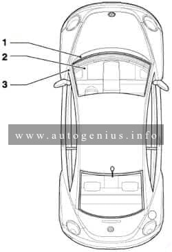
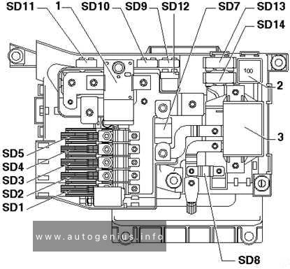
- Fuses -S162-, -S163-, -S164-, -S176-, -S177-, -S178-, -S179-, -S180- on fuse holder/battery
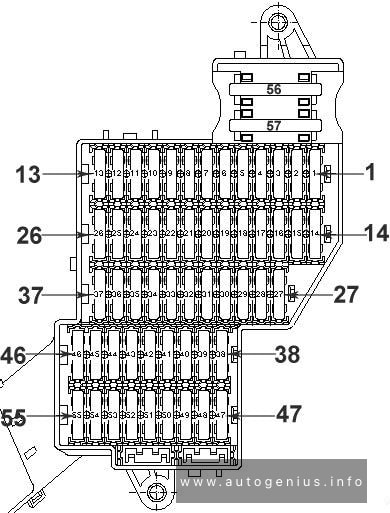
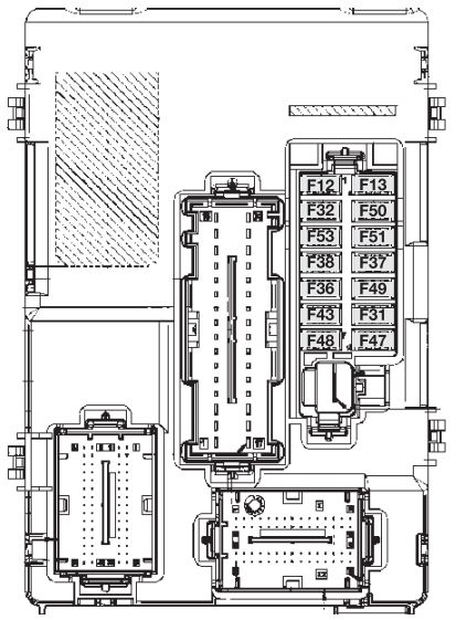
- Fuses -S43-, -S111-, -S130-, -S144-, -S283-, -S329-, -S337-, -S338-, on the 13 position additional relay carrier above the relay plate
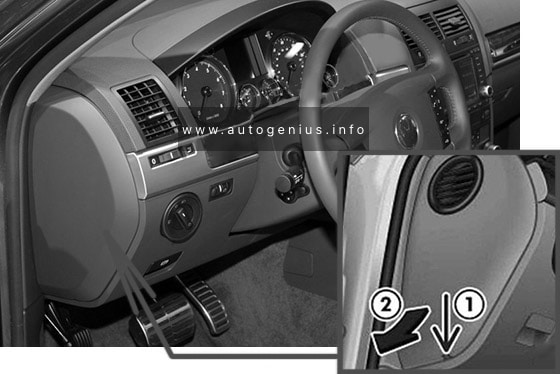
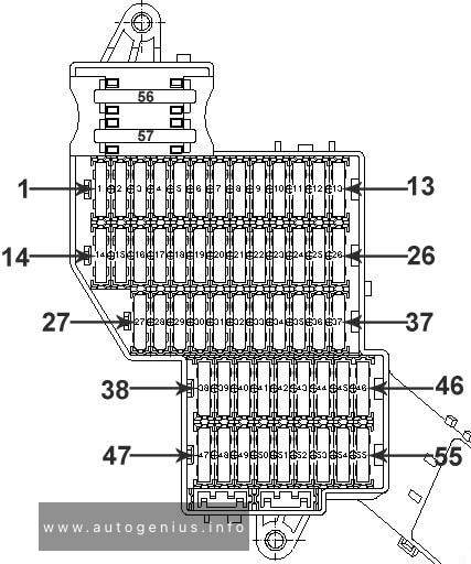
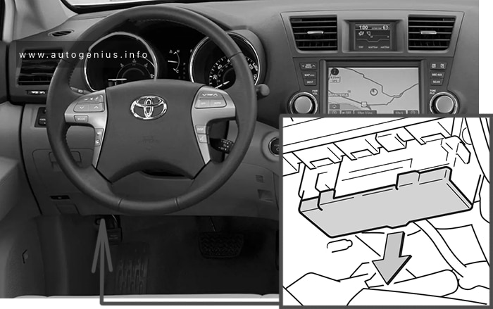
- Fuses (S) in fuse holder, left dash panel
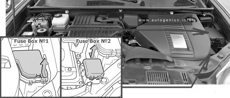
Engine compartment
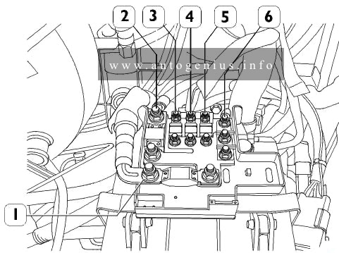
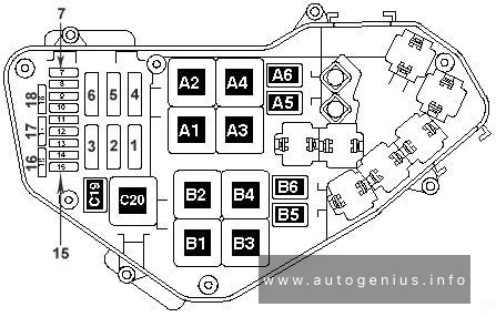
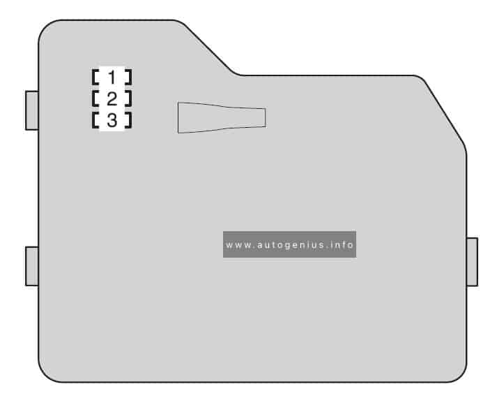
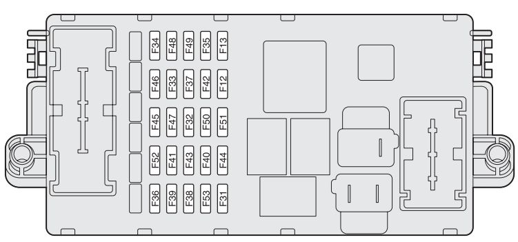
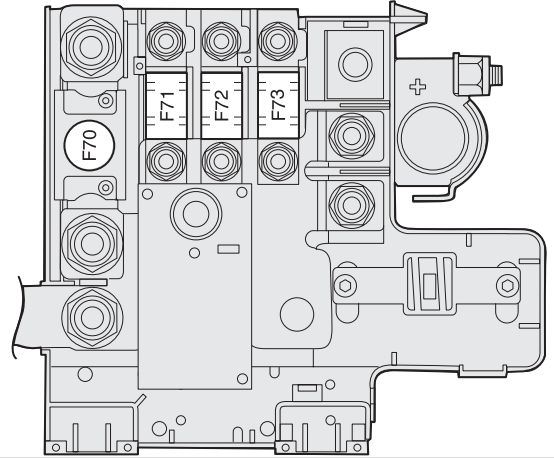
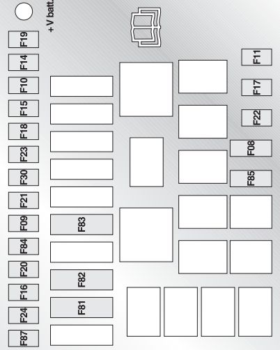
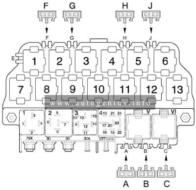
Fuses (S) on fuse holder/battery
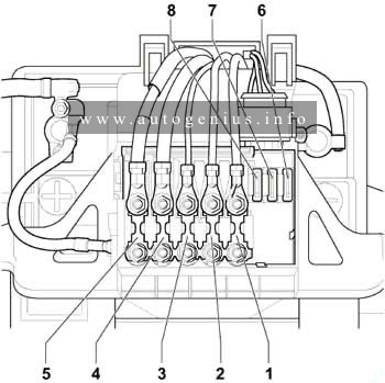
Assignment of the fuses in the engine compartment (battery)
| № | A | Function/component |
| 1 | 50 | V101 – Secondary air pump motor, models with secondary air pump only J359 – Low heat output relay, models with diesel engines, manual gearbox only J360 – High heat output relay, models with diesel engines, manual gearbox only |
| 2 | 50 | J17 – Fuel pump relay (17/30) J370 – Glow plug activation control unit, models with diesel engines only |
| 3 | 40 | J293 – Radiator fan control unit (T4e/1) V7 – Radiator fan |
| 4 | 110 | J59 – X – contact relief relay (7/30) |
| 5 | 110 150 |
C – Alternator (90A) C – Alternator (120A) |
| 6 | 30 | J104 – ABS control unit (T47a/1) |
| 7 | 30 | J104 – ABS control unit (T47a/32) |
| 8 | 30 | F18 – Radiator fan thermal switch J293 – Radiator fan control unit (T4e/3) |
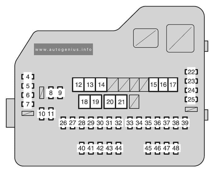
Passenger compartment
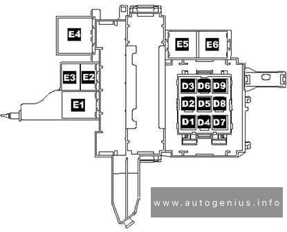
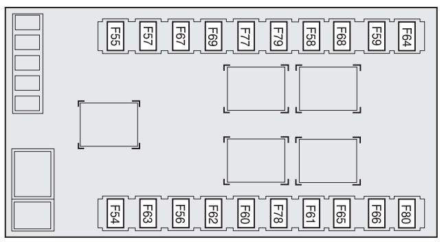
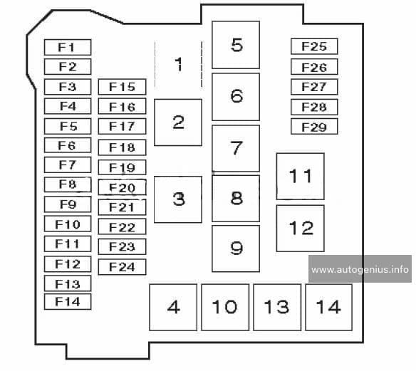
Fuses on the 13 position additional relay carrier above the relay plate
Assignment of the fuses in the passenger compartment (dashboard)
| № |
A |
Function/component |
| A | 30 | Window regulator thermal fuse -S43- |
| B | Brake vacuum pump fuse -S283-*1 Vacant*2,7 |
|
| C | 30*3 10*7 |
Rear spoiler motor fuse -S329-*3 Secondary air pump fuse -S130- |
| F | – | Vacant |
| G | – | Vacant |
| H | 15 | Anti-theft alarm system fuse and immobilizer fuse -S111-*4 Telematics fuse -S338-*5 |
| J | 15*4 20*2,6 |
Anti-theft alarm system central locking fuse -S144-*4 Brake vacuum pump fuse -S283-*2 Fuse for dual clutch gearbox mechatronic unit -S337-*6 |
| Relay positions – relay on relay plate | ||
| 1 | J4 – Dual tone horn relay (53) | |
| 2 | J59 – X-contact relief relay (100) | |
| 3 | Vacant | |
| 4 | J17 – Fuel pump relay (409) J52 – Glow plug relay (103)*8 |
|
| 5 | Automatic intermittent wash and wipe relay -J31- (377), (192), (389) | |
| Relay positions on the 13 position additional relay carrier above the relay plate | ||
| 1 | Vacant | |
| 2 | Vacant | |
| 3 | Starter inhibitor relay, clutch pedal switch -J434- (53)*9 | |
| 4 | Fog light relay -J5- (53) | |
| 5 | Vacant | |
| 6 | Vacant | |
| 7 | Daytime running lights change-over relay -J89- (173)*10 | |
| 8 | Heated exterior mirror relay -J99- (53)*11 | |
| 9 | Alarm horn relay -J641- (for telematics only) | |
| 10 | Turn signals relay for anti-theft alarm -J237- (for telematics only) Radiator fan 3rd speed relay -J135- (100) (only 1.8 l-engine) Secondary air pump relay -J299- (100) (only petrol engines, from July 2005) Low heat output relay -J359- (100) (engine code BEW only, from June 2003 up to December 2006) |
|
| 11 | Starter inhibitor and reversing light relay -J226- (126) (only for automatic gearbox 01M) Starter inhibitor relay -J207- (176) (from model year 2005; only for 6-speed automatic gearbox 09G, with Tiptronic) |
|
| 12 | Terminal 30 voltage supply relay -J317- (109) (for engine codes BPR, BPS only; models with diesel engines only) | |
| 13 | High heat output relay -J360- (53) (engine code BEW only, from June 2003 up to December 2006) | |
| 1 – for models with manual gearbox, model year 2003 2 – models with automatic gearbox, from model year 2004 3 – models with 1.8 l engine, model year 2003 up to 2005 4 – up to model year 2003 5 – from model year 2004 6 – for models with engine code BEW; with dual clutch gearbox DSG 02E; from model year 2004 7 – from model July 2005 8 – engine codes ALH, ATD, AXR, BSW only 9 – only manual gearbox 10 – daytime running lights only 11 – American markets only; only models with mechanical window regulator |
||
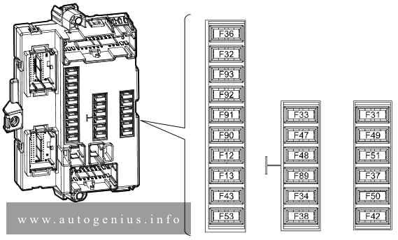
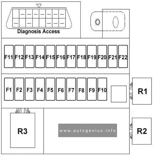
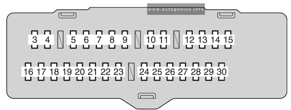
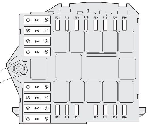
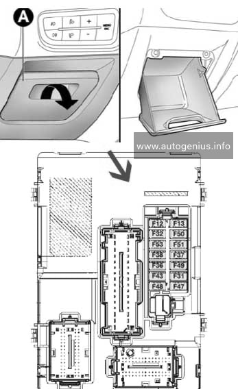
Fuses (S) in fuse holder, left dash panel
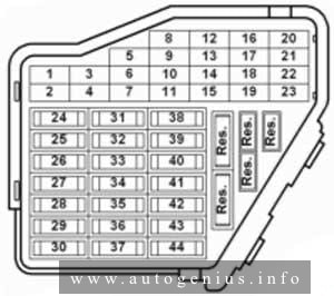
Assignment of the fuses in the passenger compartment (dashboard)
| № | A | Function/component |
| 1 | 10 | J99 – Heated exterior mirror relay*1 J131 – Heated driver seat control unit (T6/5) J132 – Heated front passenger seat control unit (T6b/5) W6 – Glove compartment light Z20/ Z21 – Left/right washer jet heater element |
| 2 | 10 | J1 – Turn signal relay (T7/6) M5/ M7 – Front left/right turn signal bulb M6/ M8 – Rear left/right turn signal bulb |
| 3 | 5 | E1 – Lighting switch E20 – Switches and instruments illumination regulator J5 – Fog light relay (4/86) |
| 4 | 5 | X – number plate light |
| 5 | 7,5 | E45 – Cruise control system switch*2 E159 – Fresh air/air recirculation flap switch (T8b/5) E184 – Fresh air and air recirculation switch*1 E227 – Cruise control system (CCS) SET button (T4q/3), CCS only*1 E231 – Exterior mirror heater button F36 – Clutch pedal switch (T4q/3) F47 – Brake pedal switch G65 – High-pressure sender (T3e/3) J89 – Daytime running lights change-over relay (8/86) J255 – Climatronic control unit (T16c/9)*1 J293 – Radiator fan control unit (T14/9) J386 – Driver door control unit (T18d/3) T16 – 16-pin connector, self-diagnosis (T16/1T16/16) V48 – Left headlight range control motor*1 V49 – Right headlight range control motor*1 Y2 – Digital clock*2 Y7 -Automatic anti-dazzle interior mirror*2 |
| 6 | 5 | J393 – Convenience system central control unit (T23/5) Vacant, model year 2004 |
| 7 | 10 | F4 – Reversing light switch F125 – Multifunction switch (T10t/10)*2 G22 – Speedometer sender J226 – Starter inhibitor and reversing light relay (T9/5) K142 – Selector lever position P/N warning lamp M16 / M17 – Left/right reversing light bulb T16 – 16-pin connector, self-diagnosis (T16/1) |
| 8 | – | Vacant J412 – Mobile telephone operating electronics control unit (T18d/10)*3 |
| 9 | 5 | E256 – TCS and ESP button (T6/6) J104 – ABS control unit (T47a/4) G85 – Steering angle sender (T6k/5) |
| 10 | 10 | J285 – Control unit in dash panel insert (T32/30) J393 – Convenience system central control unit (T23/17), models with window regulator from 2003 only R – Radio Y2 – Digital clock |
| 11 | 5 | J285 – Control unit in dash panel insert (T32/1) N110 – Selector lever lock solenoid |
| 12 | 7,5 | T16 – 16-pin connector, self-diagnosis (T16/16) J502 – Tyre pressure monitor control unit (T20b/3)*2 |
| 13 | 10 | F – Brake light switch |
| 14 | 10 | J220 – Motronic control unit (T121/62) J271 – Motronic current supply relay J393 – Convenience system central control unit (T23/22), models with window regulator from model year 2003 |
| 15 | 5 | G85 – Steering angle sender (T6p/4) for TCS/ESP J217 – Automatic gearbox control unit (T68/45) J285 – Control unit in dash panel insert (T32/23) Y2 – Digital clock*2 |
| 16 | 10 | J293 – Radiator fan control unit (T14/4) |
| 17 | – | Vacant |
| 18 | 10 | J5 – Fog light relay J285 – Control unit in dash panel insert (T32/a17) J607 – Right dip and main beam switch relay (for gas discharge bulb)*1 M32 – Right main beam bulb |
| 19 | 10 | J606 – Left dip and main beam switch relay (for gas discharge bulb)*1 M30 – Left main beam bulb |
| 20 | 15 | J607 – Right dip and main beam switch relay (for gas discharge bulb)*1 M31 – Right headlight dipped beam bulb |
| 21 | 15 | J606 – Left dip and main beam switch relay (for gas discharge bulb)*1 M29 – Left headlight dipped beam bulb |
| 22 | 5 | J285 – Control unit in dash panel insert (T32/26) M3 – Right side light bulb*2 M22 – Right brake and tail light bulb M34 – Front right side marker bulb*2 M36 – Front right turn signal and side marker bulb M38 – Rear right side marker bulb |
| 23 | 5 | J285 – Control unit in dash panel insert (T32/27) M1 – Left side light bulb*2 M21 – Left brake and tail light bulb M33 – Front left side marker bulb*2 M35 – Front left turn signal and side marker bulb M37 – Rear left side marker bulb |
| 24 | 20 | E22 – Intermittent wiper switch (T8c/8) J31 – Automatic intermittent wash and wipe relay (T18a/13), for headlight washer system only |
| 25 | 25 | E9 – Fresh air blower switch (T6d/2) J255 – Climatronic control unit (T16b/14)*1 V2 – Fresh air blower, for Climatronic only*1 |
| 26 | 25 | E15 – Heated rear window switch (T6b/5) Z1 – Heated rear window |
| 27 | 15 | U1 – Cigarette lighter, from model year 2007 J29 – Blocking diode, from model year 2007 U18 – 12 V socket -2- U19 – 12 V socket 3, in luggage compartment |
| 28 | 15 | G6 – Fuel system pressurisation pump J17 – Fuel pump relay (T9b/1)*3 |
| 29 | 15 | J220 – Motronic control unit (T121/3) J248 – Diesel direct injection system control unit (T121/37)*1 N30/ N31/ N32/ N33/ N83 – Injector, cylinder*2 J623 – Engine control unit (T80/4), engine code CBPA only*2 G70 – Air mass meter, (T5d/2), engine code BEW only, from June 2003 up to December 2006 J248 – Diesel direct injection system control unit, (T94/18), engine code BEW only, from June 2003 up to December 2006 |
| 30 | 20 | J245 – Sliding sunroof adjustment control unit (T6l/4) |
| 31 | 20 | F125 – Multifunction switch (T8a/7)*1 J217 – Automatic gearbox control unit (T68/23) J539 – Brake servo control unit (T6k/3) |
| 32 | 30 | N30/ N31/ N32/ N33 – Injector, cylinders, engine code CBPA only N280 – Air conditioning system compressor regulating valve*2 |
| 32 | 15 | J248 – Diesel direct injection system control unit (T121/2) N146 – Metering adjuster*1 |
| 33 | 20 | Vacant |
| 34 | 10 | G40 – Hall sender, engine code BEW only, from June 2003 up to December 2006 J52 – Glow plug relay (engine codes ALH and BEW only) J299 – Secondary air pump relay (T13/9)*3 J370 – Glow plug activation control unit, (6/87), engine code BEW only, from June 2003 up to December 2006 N18 – Exhaust gas recirculation valve (engine codes ALH and BEW only) N75 – Charge pressure control solenoid valve N79 – Heater element for crankcase breather*3 N108 – Commencement of injection valve (engine codes ALH and BEW only) N239 – Variable intake manifold flap change-over valve (engine codes ALH and BEW only) N205 – Inlet camshaft control valve 1 (engine codes ALH and BEW only) N249 – Turbocharger air recirculation valve (engine codes ALH and BEW only) N345 – Exhaust gas recirculation cooler change-over valve, engine code BEW only, from June 2003 up to December 2006 S130 – Secondary air pump fuse*3 V157 – Intake manifold flap motor, engine code BEW only, from June 2003 up to December 2006 |
| 35 | 30 | U19 – 12 V socket 3, in luggage compartment U10 – Trailer socket (T13/9)*3 |
| 36 | 15 | E7 – Fog light switch (T17/2) |
| 37 | 20 | J220 – Motronic control unit (T121/62) J248 – Diesel direct injection system control unit (T121/88), engine codes ALH and BEW J271 – Motronic current supply relay (1/30) J393 – Convenience system central control unit (T23/17), models with window regulator J623 – Engine control unit (T80/15), engine code CBPA only S283 – Brake vacuum pump fuse |
| 38 | 15 | E204 – Tank filler flap remote release switch E233 – Rear lid remote release button J386 – Driver door control unit (T29/19), models with window regulator J387 – Front passenger door control unit (T29a/19), models with window regulator J393 – Convenience system central control unit (T23/22)*3 |
| 39 | 15 | E3 – Hazard warning light switch (T8d/8) |
| 40 | 20 | H1 – Horn or dual tone horn J4 – Dual tone horn relay (3/30) |
| 41 | 15 | U1 – Cigarette lighter U5 – 12 V socket U18 – 12 V socket -2-, from 07.03 U19 – 12 V socket 3, in luggage compartment, from 07.03 Vacant*3 |
| 42 | 25 | R – Radio (T8/5, T8/7) |
| 43 | 10 | G39 – Lambda probe G70/G42 – Air mass meter/ Intake air temperature sender, engine codes BPS, BPR only G108 – Lambda probe 2 G130 – Lambda probe after catalytic converter G465 – Centre Lambda probe for bank 1 catalytic converter, engine code BPR only J299 – Secondary air pump relay (4/85)*1 N80 – Activated charcoal filter system solenoid valve 1 N112-Secondary air inlet valve*1 V144 – Fuel system diagnostic pump |
| 43 | 10 | F36 – Clutch pedal switch F47-Brake pedal switch J359 – Low heat output relay J360 – High heat output relay N79-Heater element for crankcase breather |
| 44 | 15 | J131 – Heated driver seat control unit (T6/4) J132 – Heated front passenger seat control unit (T6b/4) |
| 1 – model year 2002 up to july 2005 2 – from model July 2005 3 – from model July 2009 |
||
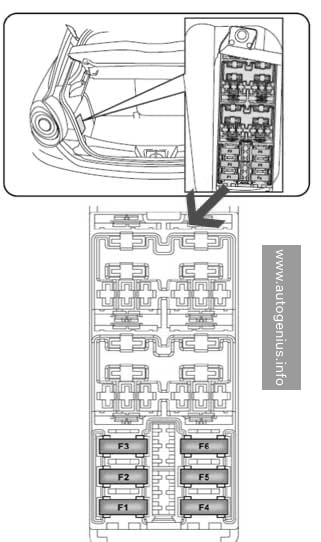
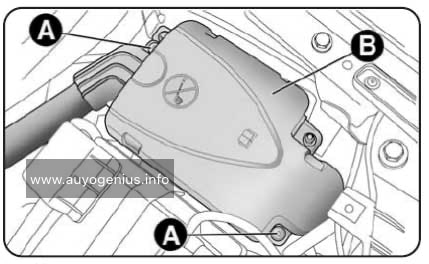
J179 – Automatic glow period control unit*¹,²
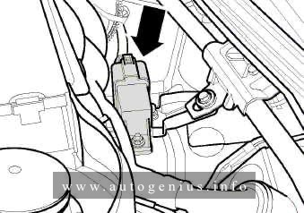
Location: in centre of plenum chamber ⇒ -arrow-
1) engine code BEW only
2) from June 2003 up to December 2006
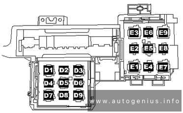
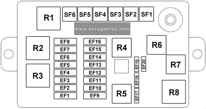
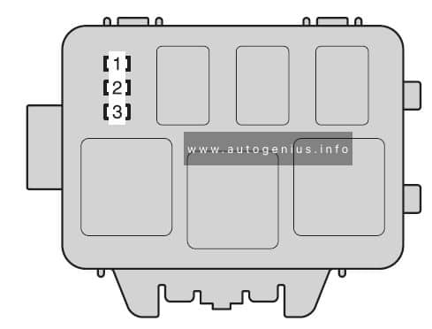
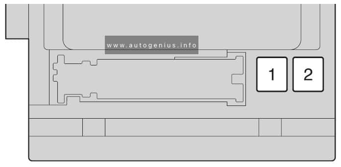
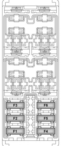
Additional relay carrier
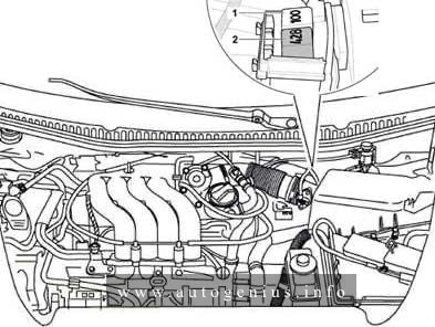
Assignment of the fuses in the additional relat carrier
| № | Function/component |
| 1 | Secondary air pump relay -J299- (100)*1 High heat output relay -J360- (100)*2 |
| 2 | Motronic current supply relay -J271- (458)*1 Low heat output relay -J359- (53)*2 |
| 1 – petrol engines only 2 – diesel engines only |
|
WARNING: Terminal and harness assignments for individual connectors will vary depending on vehicle equipment level, model, and market.