Dodge RAM 1500 (1994 – 1997) – fuse and relay box diagram
Year of production: 1994, 1995, 1996, 1997
The Dodge Ram 1500 from 1994 to 1997 was a key model in the history of Dodge trucks, marking the debut of the second generation of the Dodge Ram series. This generation saw a radical redesign that helped revitalize Dodge’s truck sales, making the Ram one of the most iconic pickup trucks of the 1990s.
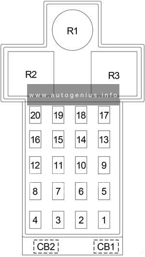
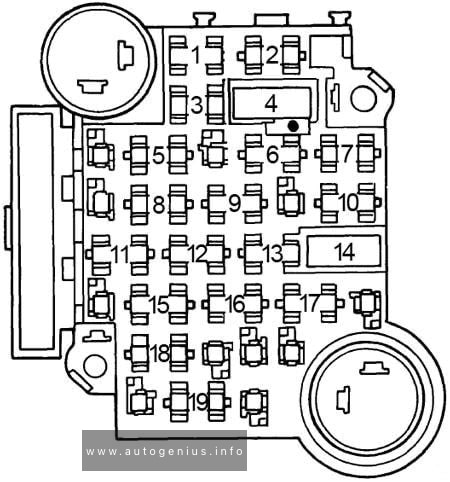
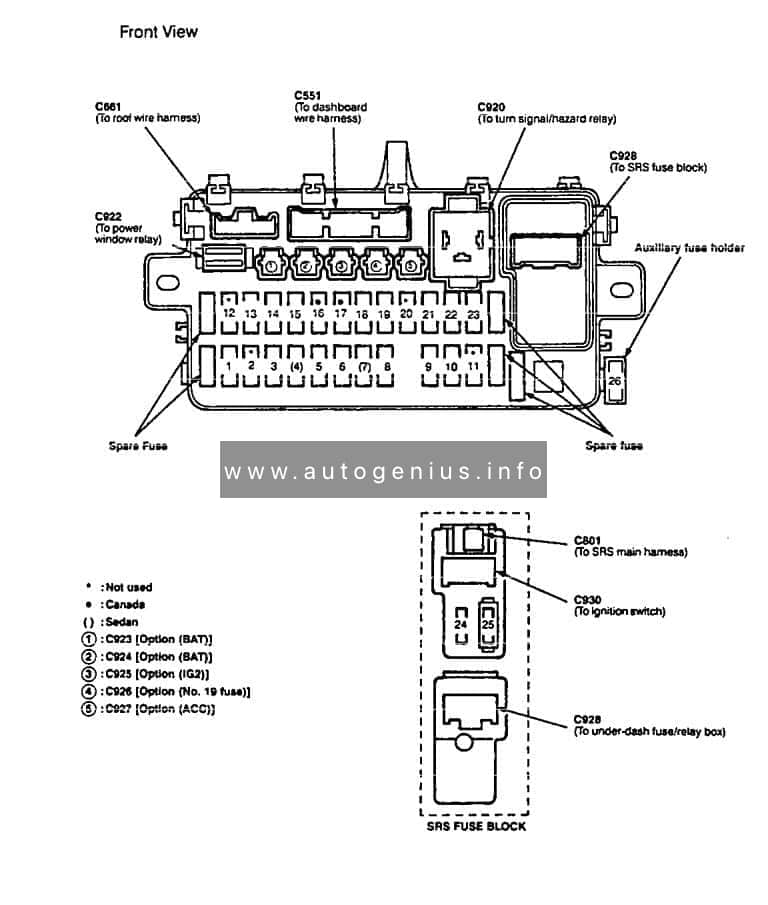
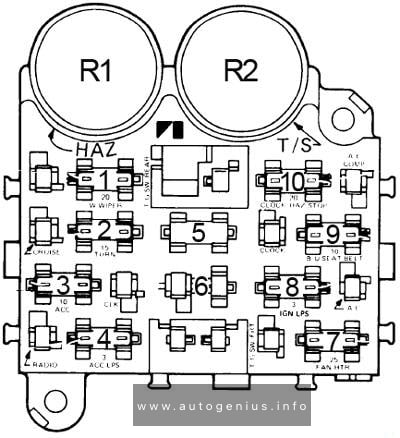
Passenger Compartment Fuse Box
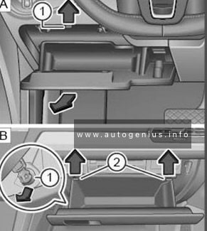
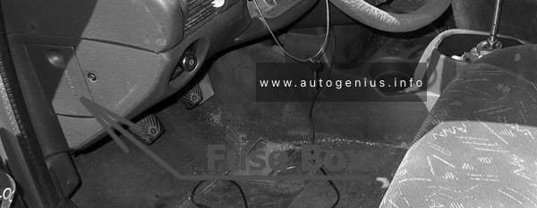
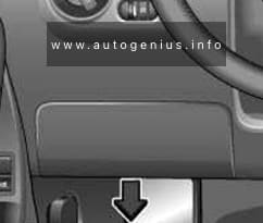
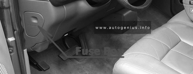
Fuse Box Location
The fuse panel is located behind the cover on the driver’s side of the instrument panel.
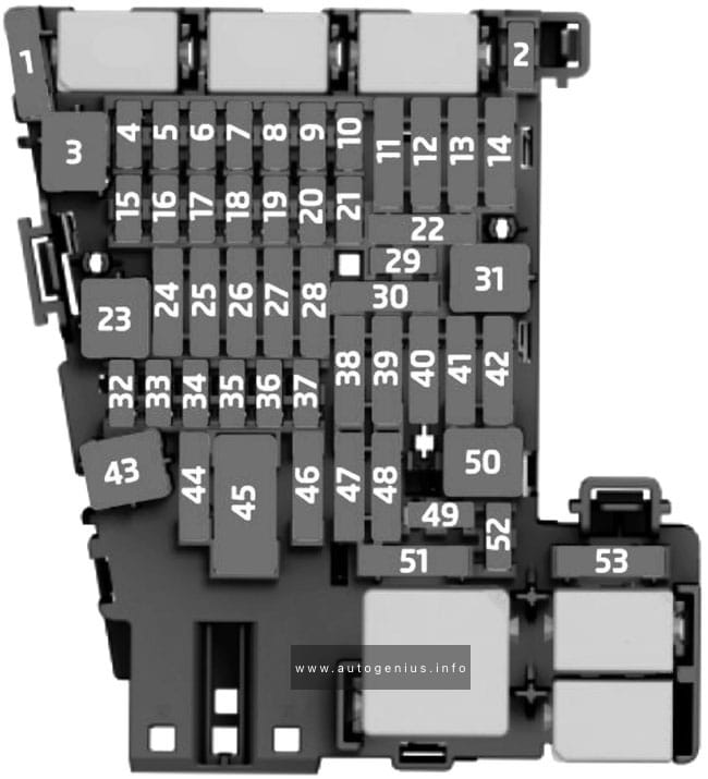
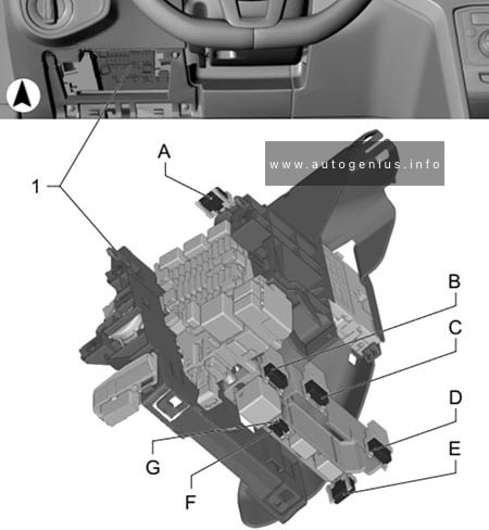
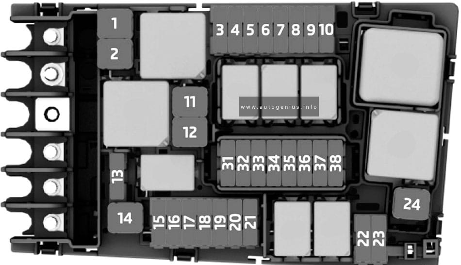
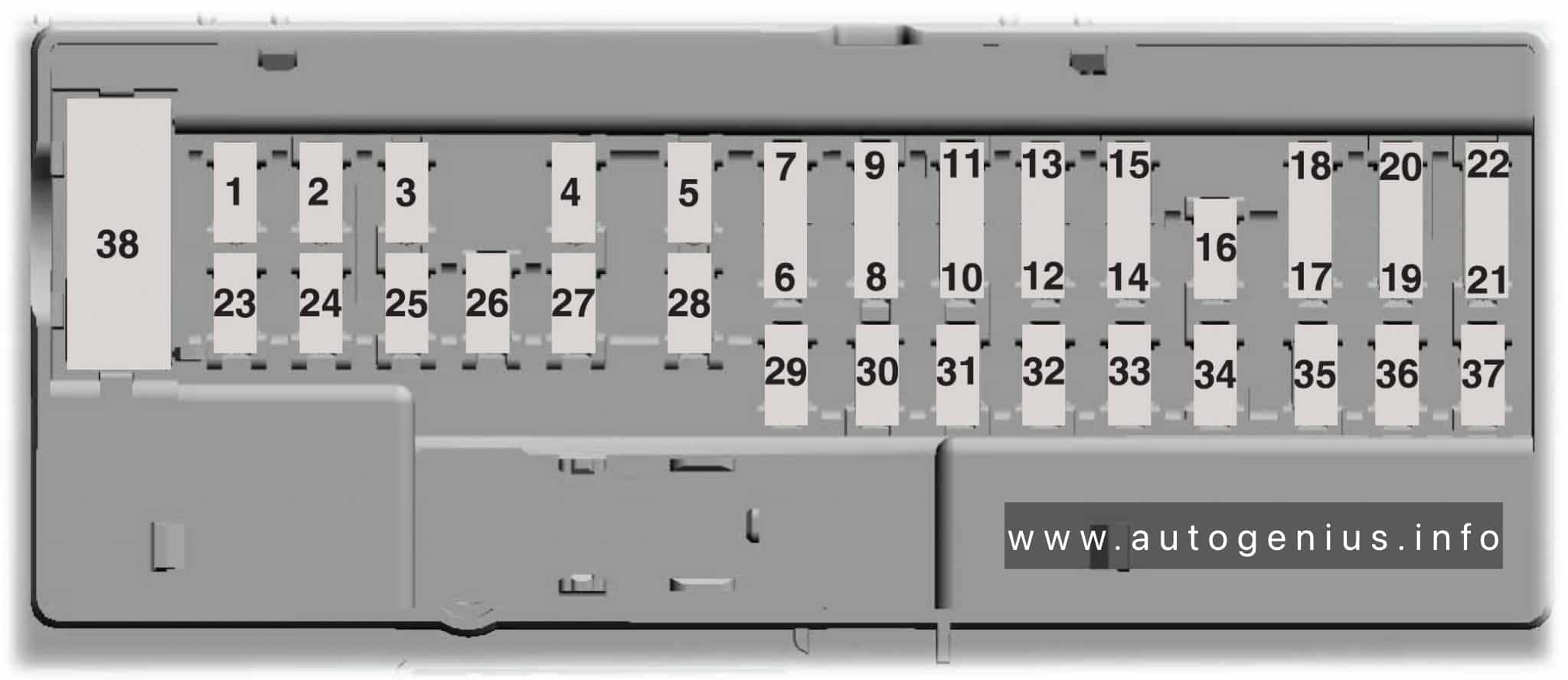
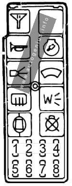
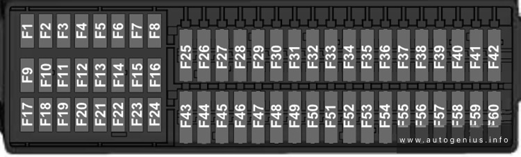
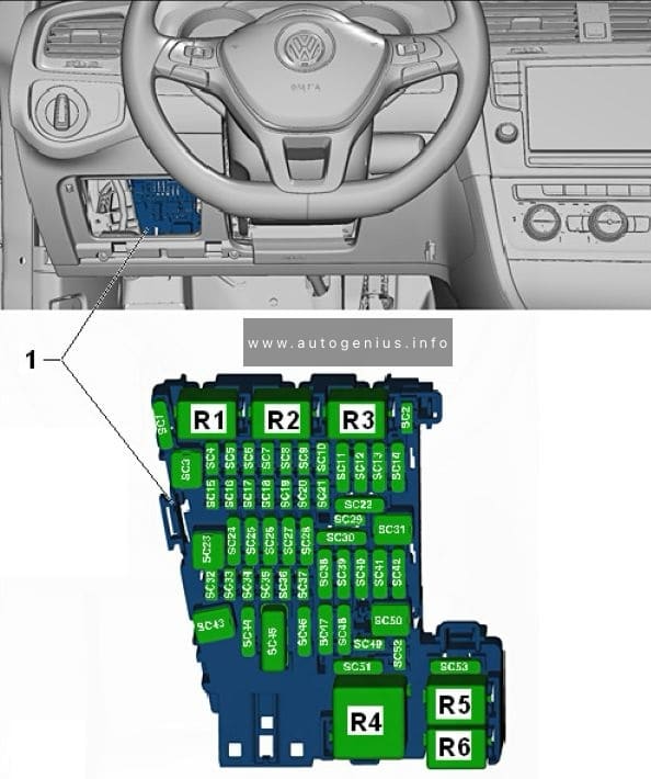
Fuse Box Diagram
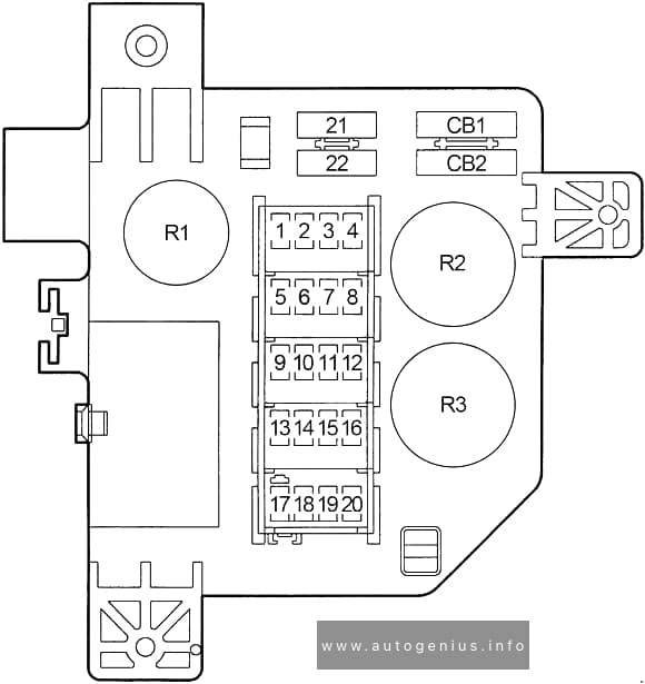
Assignment of fuses in the passenger compartment (1994-1997)
| No. |
A |
Protected Component |
| 1 | 20 | ’96-’97: Power Outlet |
| 2 | – | – |
| 3 | – | – |
| 4 | – | – |
| 5 | 20 | Cigar Lighter, Power Outlet (’94-’95) |
| 6 | 15 | ’94-’95: Turn Signal Flasher |
| 20 | ’96-’97: Turn Signal Flasher | |
| 7 | 10 | ’94-’95: Radio |
| 15 | ’96-’97: Radio | |
| 8 | 20 | Intermittent Wiper Control Module, Remote Keyless Entry (’96-’97), Intermittent Wiper Switch, Windshield Wiper Motor, A/C Clutch (Diesel (’94-’95)) |
| 9 | 10 | Fuel Pump Relay, A/C Compressor Clutch Relay, Automatic Shutdown Relay, Transmission Overdrive Solenoid, EGR Solenoid, Powertrain Control Module (PCM), Ignition Module, High Pressure Fuel Shut-Off Solenoid Relay (CNG Models Only), EGR Solenoid (CNG Models Only), Fuel Shutdown Solenoid, Heated Intake Air System Relays, Diagnostic Connector, Automatic Shut Down Relay, Duty Cycle EVAP/Purge Solenoid |
| 10 | 2 | ’94-’95: Vehicle Speed Control |
| 11 | 10 | Overdrive Switch, Buzzer Module, Overhead Console |
| 12 | 15 | Airbag Diagnostic Module, Instrument Cluster, Message Center, Diesel Wait-To-Start and Water-In Fuel Lamps. |
| 13 | 5 | Illumination, Fog Lamp Switch, Overdrive Switch, Instrument Cluster, A/C Heater Control, Overhead Console, Radio |
| 14 | 20 | ’94-’95: RWAL and ABS Module |
| 20 | ’96-’97: Control Anti-Lock Brake, ABS Pump Motor Relay, ABS Warning Lamp Relay, Vacuum Sensor | |
| 15 | 15 | Automatic Day/Night Mirror, Back-up Lights (Park/Neutral Position Switch (A/T), Back-Up Lamp Switch (M/T), Daytime Running Lamps |
| 16 | 15 | Airbag Diagnostic Module |
| 17 | 15 | Ignition Off Draw, Clock Memory, Underhood Lamp, Power Mirror Switch, Time Delay Relay, Buzzer Module, Data Link Connector, Radio Choke Relay, Glove Box Lamp Switch, Radio |
| 18 | 15 | ’94-’95: Parking Lamps |
| 15 | ’96-’97: Headlamp Switch, Radio, Overhead Console, Fog Lamp Relay | |
| 19 | 20 | Power Door Locks |
| 20 | 15 | Stop Lamps, Controller Anti-Lock Brake (’96-’97) |
| 21 | – | – |
| 22 | 30 | Blower Motor |
| CB1 | 30 | Circuit Breaker: Power Windows |
| CB2 | 30 | Circuit Breaker: Power Seats |
| Relay | ||
| R1 | Time Delay | |
| R2 | Hazard Warning Flasher | |
| R3 | Turn Signal Flasher | |
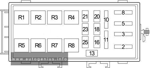
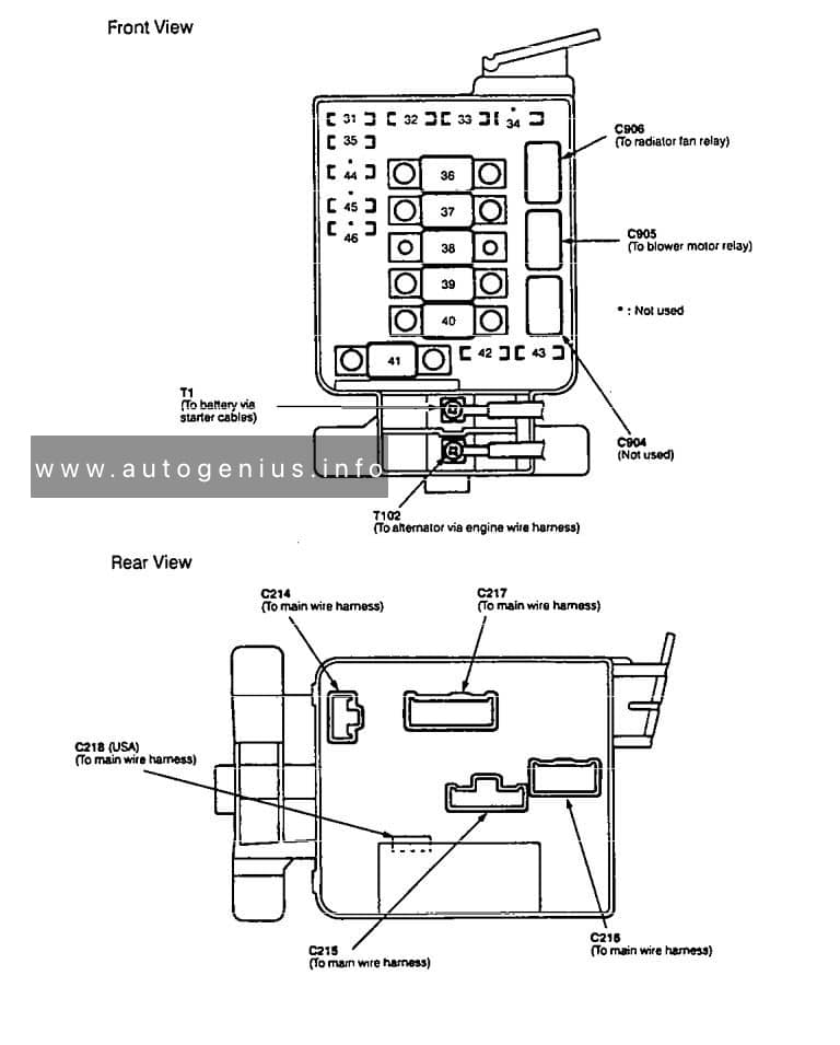
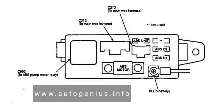
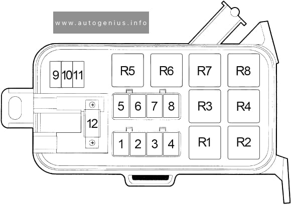
Engine Compartment Fuse Box
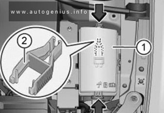
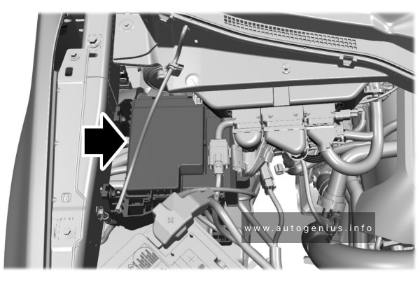
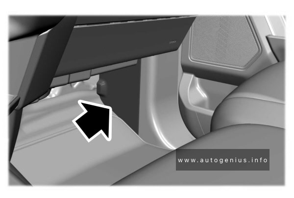
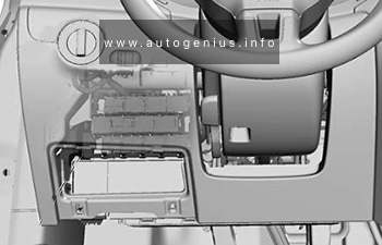
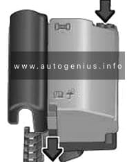
Fuse Box Location
The fuse box is near the battery.
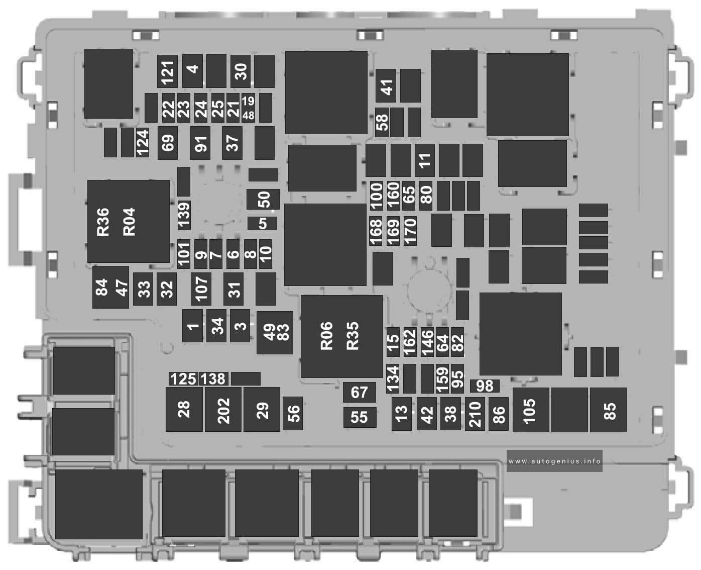
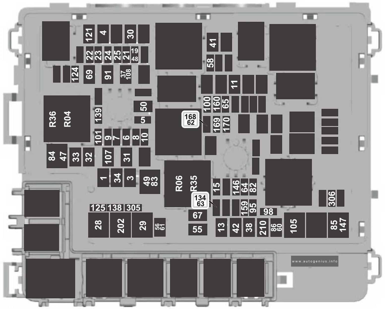
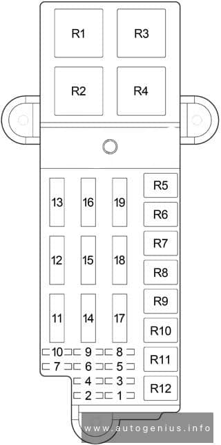
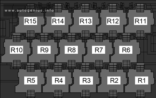
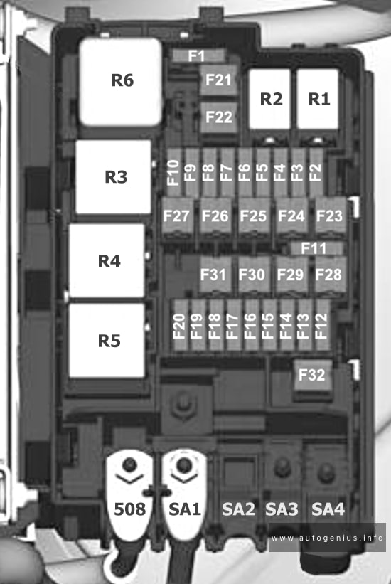
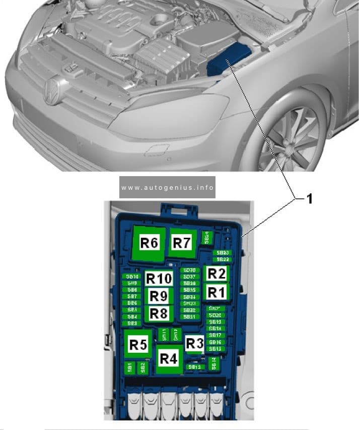
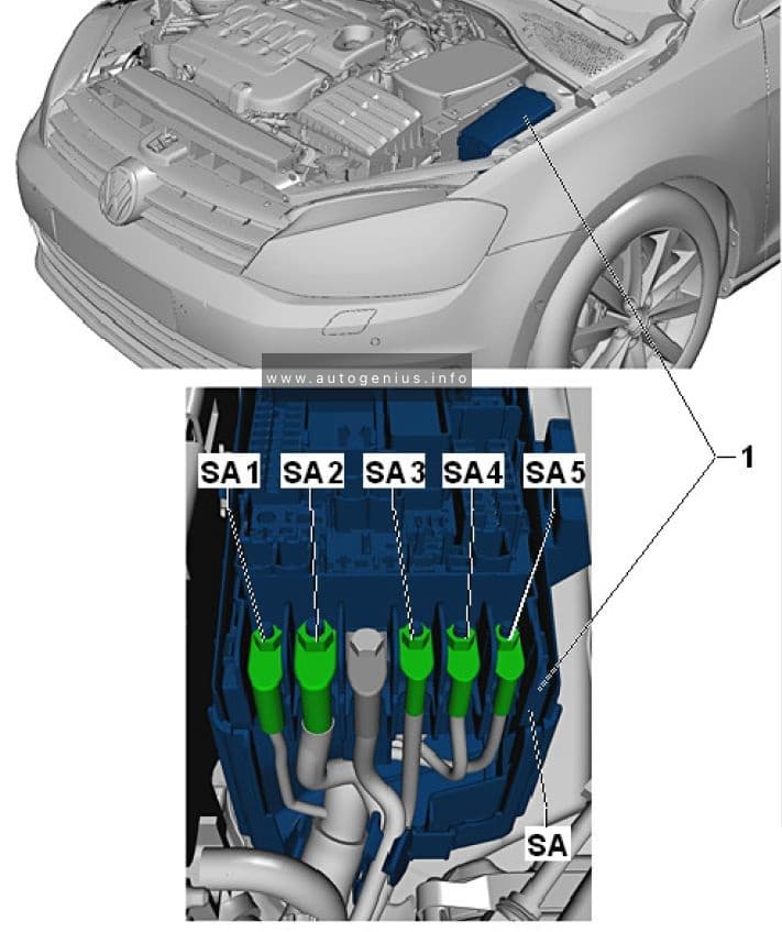
Fuse Box Diagram
’94-’95:
’96-’97:
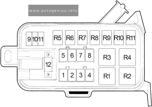
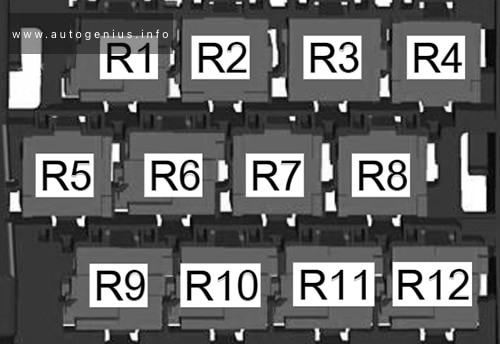
Assignment of fuses and relay in the engine compartment (1994-1997)
| No. |
A |
Protected Component |
| 1 | 50 | Power Distribution Center, Fuse Block |
| 2 | 40 | Fuse Block, Ignition Switch, Ignition Starter Motor Relay |
| 3 | 40 | Ignition Switch, Fuse Block |
| 4 | 30 | Automatic Shut Down Relay, Oxygen Sensors, Powertrain Control Module (PCM), Fuel Injectors, Ignition Coils, EGR Control Module |
| 5 | 20 | ’94-’95: Fuel Pump |
| 40 | ’96-’97: ABS Pump Motor Relay, Hydraulic Control Unit, Controller Anti-Lock Brake & Rear Wheel Anti-Lock Valve | |
| 6 | 30 | ’94-’95: Trailer Lamps |
| 40 | ’96-’97: Daytime Running Lamp Module, Fuse Block, Headlamp Switch, Headlamp Dimmer Switch | |
| 7 | 40 | ’94-’95: Stop/Headlamp |
| ’96-’97: Electronic Brake Provision, Trailer Tow Relay, Trailer Toe Connector | ||
| 8 | 40 | ’94-’95: ABS Pump |
| 20 | ’96-’97: Fuel Pump Relay, Transmission Control Relay, Powertrain Control Module, Fuel Pump Module, Transmission Solenoid Assembly | |
| 9 | 15 | ’96-’97: Fog Lamp Relay, Fog Lamp Switch |
| 10 | 20 | A/C Compressor Clutch, Horn Relay |
| 11 | 15 | ’94-’95: Hazard Warning Flasher |
| 20 | ’96-’97: Hazard Warning Flasher | |
| 12 | 120 | Generator |
| Relay | ||
| R1 | Anti-Lock Brake System / Dual Tank 3 | |
| R2 | Starter | |
| R3 | ’94-’95: ABS Warning Light | |
| ’96-’97: Automatic Shut Down | ||
| R4 | Fuel Pump | |
| R5 | ’94-’95: Trailer Lamps | |
| ’96-’97: Fog Lamp (No.1) / Dual Tank 1 | ||
| R6 | ’94-’95: Horn | |
| ’96-’97: Fog Lamp (No.2) / Dual Tank 2 | ||
| R7 | ’94-’95: Air Conditioning Clutch | |
| ’96-’97: ABS Warning Light | ||
| R8 | ’94-’95: Automatic Shut Down | |
| ’96-’97: Trailer | ||
| R9 | ’96-’97: Horn | |
| R10 | ’96-’97: Air Conditioning Clutch | |
| R11 | ’96-’97: Transmission Control | |
WARNING: Terminal and harness assignments for individual connectors will vary depending on vehicle equipment level, model, and market.