This article focuses on the fifth-generation Honda Prelude (BB5–BB9), manufactured between 1996 and 2001. It includes fuse box diagrams for the 1997, 1998, 1999, 2000, and 2001 models, along with information on the location of the fuse panels inside the vehicle and details about each fuse’s function (fuse layout).
Passenger Compartment Fuse Box
Fuse Box Location
The interior fuse box is underneath the dashboard on the driver’s side. To open it, turn the knob as shown.
Ford F-350 (1992 – 1997) – fuse and relay box diagram
Year of production: 1992, 1993, 1993, 1994, 1995, 1996, 1997
This article focuses on the ninth-generation Ford F-Series, produced from 1992 to 1997. It provides fuse box diagrams for the 1992, 1993, 1994, 1995, 1996, and 1997 Ford F-150, F-250, and F-350 models, along with information on the locations of the fuse panels within the vehicle and the assignment of each fuse and relay (fuse layout).
Passenger Compartment Fuse Panel
Fuse box location
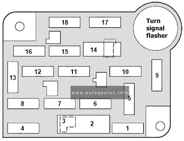
The fuse panel is located behind the cover to the left of the steering wheel. Remove the cover from the lower edge of the instrument panel by pulling on handle to disengage the fasteners.
Fuse box diagram
Ford F-350 – fuse and relay box diagram – passenger compartment
Ford F-250 (1992 – 1997) – fuse and relay box diagram
Year of production: 1992, 1993, 1993, 1994, 1995, 1996, 1997
This article focuses on the ninth-generation Ford F-Series, produced from 1992 to 1997. It provides fuse box diagrams for the 1992, 1993, 1994, 1995, 1996, and 1997 Ford F-150, F-250, and F-350 models, along with information on the locations of the fuse panels within the vehicle and the assignment of each fuse and relay (fuse layout).
Passenger Compartment Fuse Panel
Fuse box location
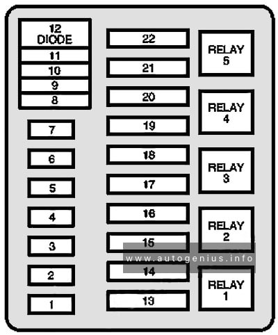
The fuse panel is located behind the cover to the left of the steering wheel. Remove the cover from the lower edge of the instrument panel by pulling on handle to disengage the fasteners.
Fuse box diagram
Ford F-250 – fuse and relay box diagram – passenger compartment
Year of production: 2010 2011, 2012, 2013, 2014, 2015, 2016
This article covers the first-generation Dacia Duster, produced from 2010 to 2016 It includes fuse box diagrams for the 2010, 2011, 2012, 2013, 2014, 2015 and 2016 models, provides details on the location of the fuse panels inside the vehicle, and explains the function and layout of each fuse.
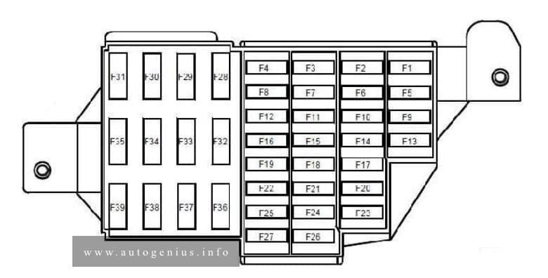
Driver’s dual rear electric window control – child safety relay control
F14
30
Driver’s dual front electric window control
F15
10
Anti-lock braking system ECU
F16
15
Radio
F17
15
Main electromagnetic horn – secondary electromagnetic horn
F18
10
Rear left-hand side light – front left-hand side light
F19
10
Rear right-hand side light – passenger storage compartment light – instrument panel – UCH – hazard warning lights control – air conditioning control panel – radio – central door locking switch – first row cigarette lighter – 4×4 mode control – right-hand number plate light – left-hand number plate light – front right-hand side light – traction control switch – heated rear screen control – parking proximity sensor switch
F20
7,5
Rear fog light
F21
5
Instrument panel
F22
—
—
F23
15
Fuse on alarm version: Supply to horns via horn relay on board
F24
—
—
F25
—
—
F26
5
Airbag and pretensioner control unit
F27
20
Rear screen wiper motor – wash/wipe combination switch – reversing lights switch – neutral and reversing sensor on manual gearbox – automatic gearbox module – parking proximity sensor electronic control unit
F28
15
Consumer cut-out – instrument panel – radio – UCH
F29
15
UCH – diagnostic socket – anti-theft tracker unit
F30
20
UCH
F31
15
Supply to front right-hand and left-hand fog light via front fog relay on board – instrument panel indicator light
F32
30
heated rear screen switch
F33
—
—
F34
15
Front-rear torque distribution electric control unit
F35
—
—
F36
30
Cold air blower unit supply via cold air blower unit relay and air conditioning control panel
F37
5
Right-hand and left-hand electric door mirror supply via electric door mirror control
F38
15
Radio – first row cigarette lighter
F39
10
Cold air blower unit relay control
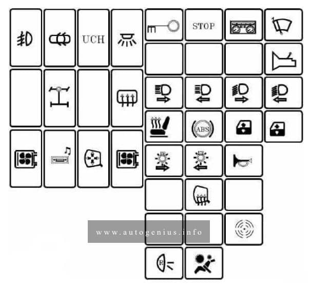
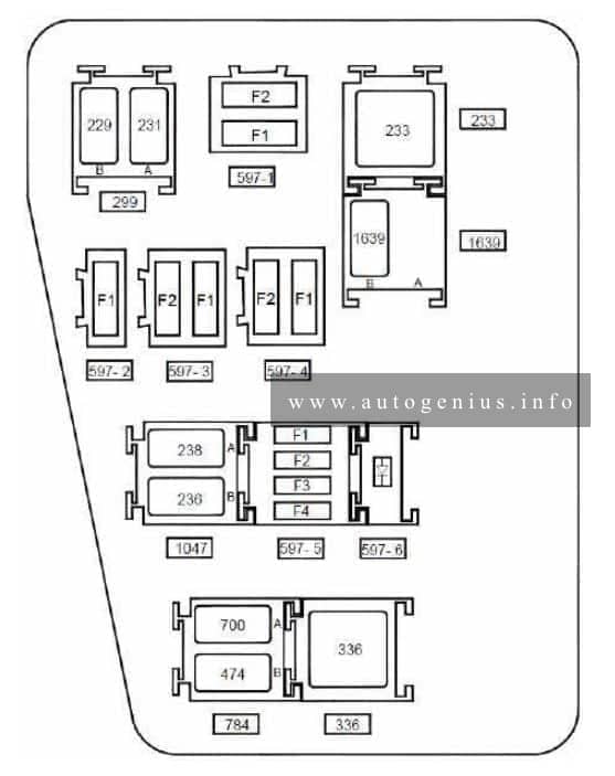
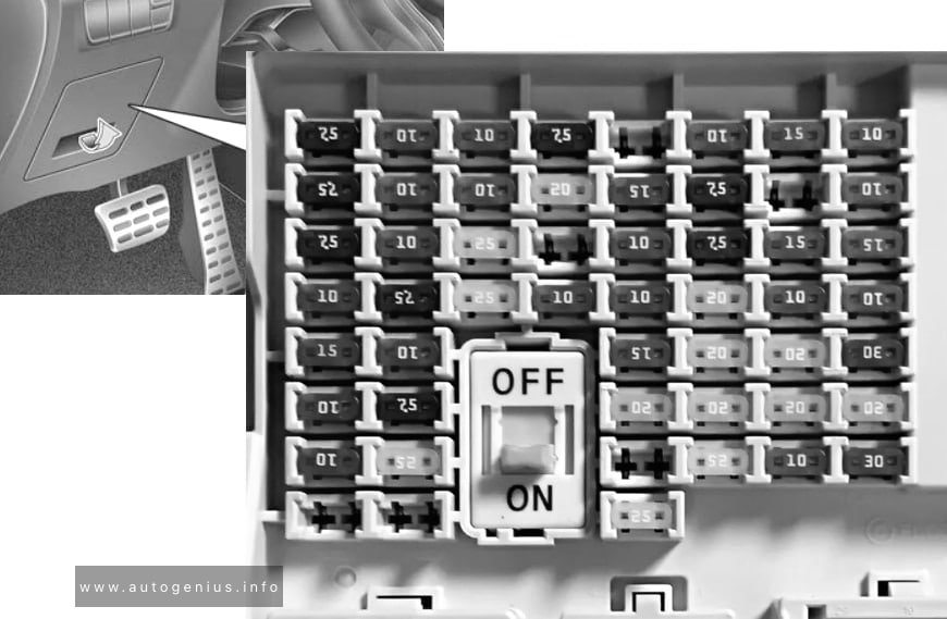
Relay box location
This relay is located in the passenger compartment, in the lower left-hand section of the dashboard
Anti-lock braking system electric control unit on versions without electronic stability program
F2
25
Anti-lock braking system electric control unit on versions without electronic stability program
Fuse board 597- 2
F1
40
Fuse on air conditioning version: Cooling fan assembly supply via fan assembly high-speed relay or via fan assembly low speed relay on relay board and fan assembly resistor – air conditioning clutch supply via air conditioning clutch relay on board
Fuse board 597- 3
F1
60
Ignition switch – monolever – supply to fuse F23 on passenger compartment fuse box
F2
60
Monolever supply – supply to fuses F29 and F36 on passenger compartment fuse box
Fuse board 597- 4
F1
—
—
F2
25
F34 fuse supply on passenger compartment fuse box on 4×4 version (four wheel drive)
Fuse board 597- 5
F1
30
Fuse on standard heating version: cooling fan assembly supply via low speed fan assembly relay on relay board
F2
25
Injection locking relay control and supply on relay board – fuel pump relay supply on relay board
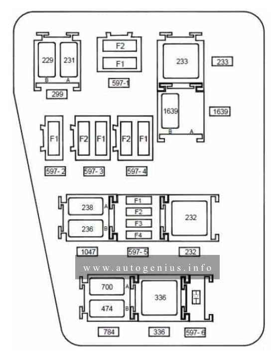
Anti-lock braking system electric control unit on versions without electronic stability program
F2
25
Anti-lock braking system electric control unit on versions without electronic stability program
Fuse board 597- 2
F1
40
Fuse on air conditioning version: cooling fan assembly supply via high speed fan assembly relay or via low speed fan assembly relay on relay board and fan assembly resistor
Fuse board 597- 3
F1
60
Ignition switch – monolever – supply to fuse F23 on passenger compartment fuse box
F2
60
Monolever supply – supply to fuses F29 and F36 on passenger compartment fuse box
Fuse board 597- 4
F1
—
—
F2
25
F34 fuse supply on passenger compartment fuse box on 4×4 version (four wheel drive)
Fuse board 597- 5
F1
15
Fuse on air conditioning version: Air conditioning clutch supply via air conditioning clutch relay on board
F2
25
Injection locking relay control and supply on relay board – fuel pump relay supply on relay board
F3
—
—
F4
15
Automatic gearbox electric control unit (119) with 4-speed automatic gearbox on F4R403 and F4R405 engines
Diode 597- 6 support plate
Diode
Air conditioning clutch
Relay board 299
A
20
Front fog lights
B
20
Horn
Unit relay 233
233
40
Cold air blower
Relay board 1047
A
20
Injection locking
B
20
Fuel pump
Relay board 784
A
20
Low speed fan assembly
B
20
Air conditioning clutch
Unit relay 336
336
40
High speed fan assembly
Unit relay 232 on automatic gearbox version
22
40
Starter
Relay 1639 board on FLEXFUEL version
A
—
—
B
20
Additional fuel pump
WARNING: Terminal and harness assignments for individual connectors will vary depending on vehicle equipment level, model, and market.
Year of production: 2017, 2018, 2019, 2020, 2021, 2022
The 4th generation Kia Sportage was produced in 2016, 2017, 2018, 2019, 2020, 2021, 2022, 2023 with both gasoline and diesel engines. In this publication you will find a designation of the 4th generation Kia Sportage fuses and relays with boxes diagrams and their locations. Let’s highlight the fuse responsible for the cigarette lighter.
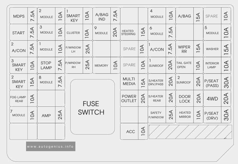
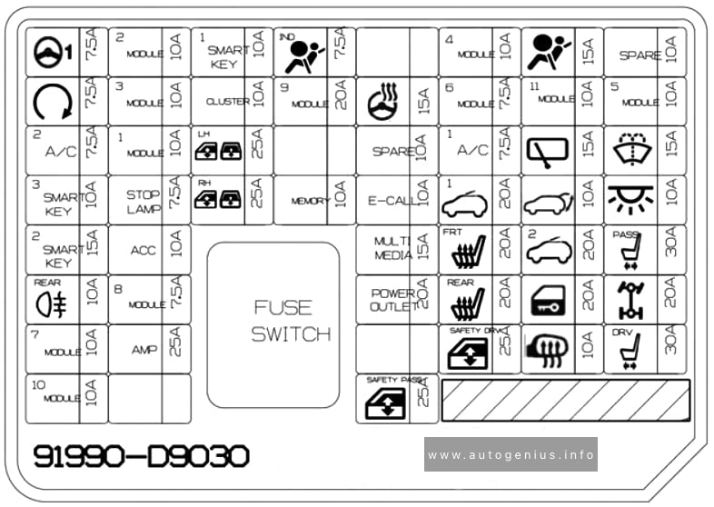
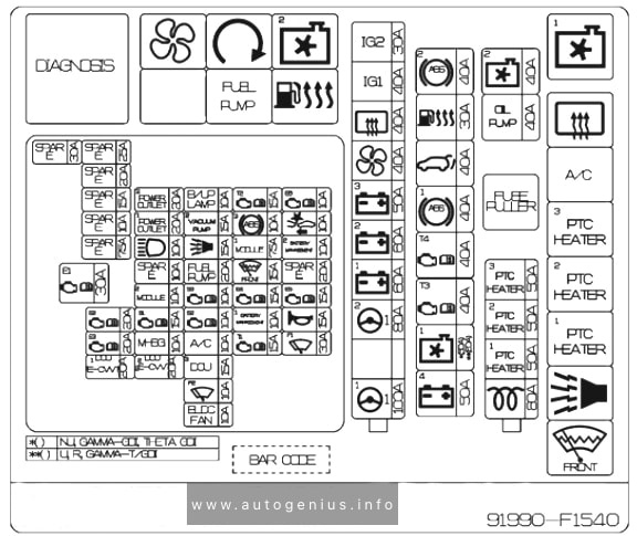
Instrument panel (driver’s side fuse panel)
Fuse box location
Located under the dashboard on the driver’s side behind the protective cover.
Front/Rear Seat Warmer Control Module, ATM Shift Lever ILL., Front Air Ventilation Seat Control Module, A/V & Navigation Head Unit, Electro Chromic Mirror, Audio, A/C Control Module, Multipurpose Check Connector, Adaptive Front Lighting Module
Driver/Passenger Power Outside Mirror, A/C Control Module
P/SEAT (DRV)
30
Driver Seat Manual Switch
ACC
10
Rear USB Charger, AMP, Power Outside Mirror Switch, PCB Block(Power Outlet Relay), Smart Key Control Module, Audio, A/V & Navigation Head Unit, BCM, Wireless Charger
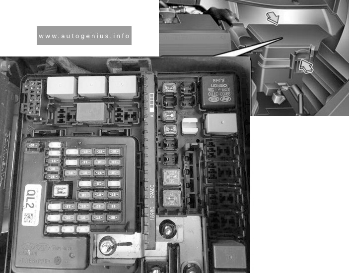
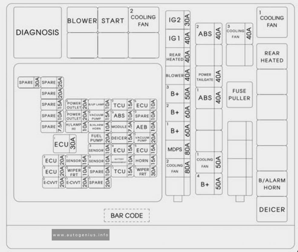
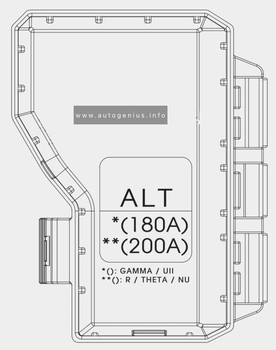
Engine compartment fuse panel
Fuse box location
Located on the left side of the engine compartment.
Cadillac Eldorado (1994) – fuse and relay box diagram
Year of production: 1994
This article covers the Cadillac Eldorado, produced from 1953 to 2002. The CadillacEldorado was one of the longest-produced luxury coupé models in the history of American automotive manufacturing.
Inside, you’ll find fuse box diagrams for the 1994 models, along with details on the location of the fuse panels within the vehicle and information on the function and layout of each fuse and relay.
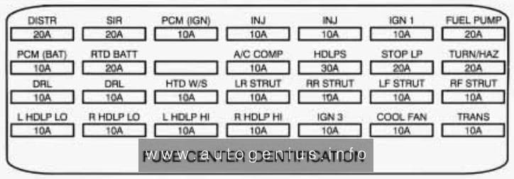
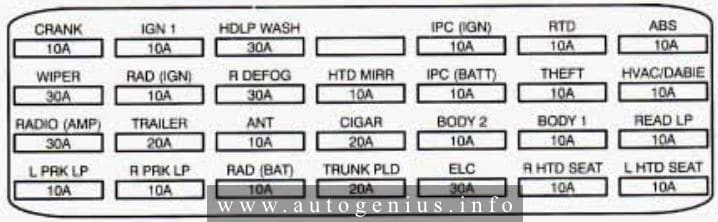
Engine compartment fuse block
Fuse box location
The maxi fuse and relays are located next to the engine compartment fuse block.
FRONT DOOR LOCK SWITCHES, FRONT DOOR COURTESY LAMP, GLOVE BOX LAMP, HEADLIGHT SWITCH
READ LP
10
LTAND AT FRONT HEADER LAMP, GARAGE DOOR OPENER, LT AND RT REAR HEADER LAMPS
L PRK LP
10
LT REAR TAIL/STOP/TURN LAMPS, LT FRONT PARK/TURN LAMPS, FRONT AND REAR LEFT SIDE MARKER LAMPS, RT REAR MARKER LAMP, HEADLIGHT SWITCH, INSTRUMENT PANEL CLUSTER
R PRK LP
10
RADIO CONTROL HEAD, RT TAIUSTOP TURN LAMPS, RT FRONT AND REAR SIDE MARKER LAMPS, RT FRONT PARK AND TURN LAMPS, ENGINE COME LAMP, LICENSE PLATE LAMPS
RAD (BAT)
10
RADIO
TRUNK PLD
20
TRUNK LID PULL DOWN MOTOR
ELC
30
ELECTRONIC LEVEL CONTROL (ELC)
R HTD SEAT
10
PASSENGERS HEATED SEAT
L HTD SEAT
10
DRIVER’S HEATED SEAT
WARNING: Terminal and harness assignments for individual connectors will vary depending on vehicle equipment level, model, and market.
This article covers the Cadillac Eldorado, produced from 1953 to 2002. The Cadillac Eldorado was one of the longest-produced luxury coupé models in the history of American automotive manufacturing.
Inside, you’ll find fuse box diagrams for the 1992 and 1993 models, along with details on the location of the fuse panels within the vehicle and information on the function and layout of each fuse and relay.
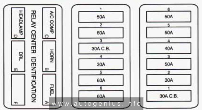
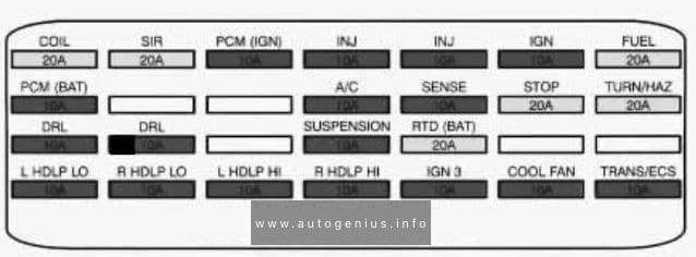
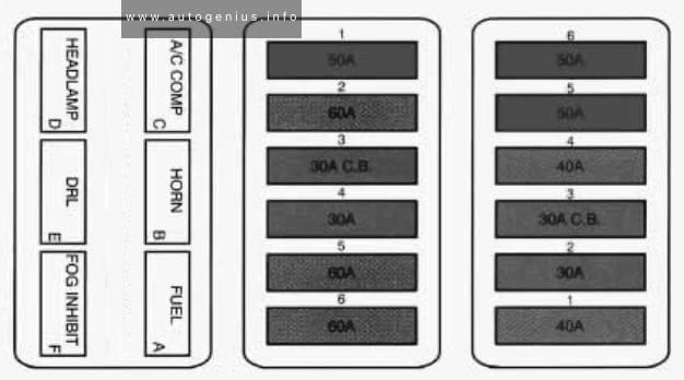
Engine compartment
Maxi Fuse/Relay Center
The maxi fuse and relays are located next to the engine compartment fuse block.
Buick Century (VI; 1997 – 1999) – fuse and relay box diagram
Year of production: 1997, 1998, 1999
This article covers the Buick Century. It includes fuse box diagrams for the 6th generation 1997 models, provides details on the location of the fuse panels inside the vehicle, and explains the function and layout of each fuse.
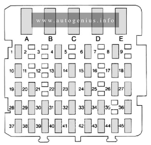
Passenger compartment
Fuse box location
The fuse box is located on right side of the instrument panel, behind the cover.
This article covers the Buick Century. It includes fuse box diagrams for the 5th generation 1995 models, provides details on the location of the fuse panels inside the vehicle, and explains the function and layout of each fuse.
Passenger compartment
Fuse box location
The fuse panel is located inside the glove box, on the left side.
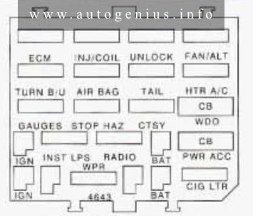
Fuse box diagram
Buick Century (V; 1996) – fuse and relay box diagram – passenger compartment
Assignment of the fuses in the passenger compartment (instrument panel)
Fuse
Usage
ECM
Powertrain Control Module
TNJ/COIL
Fuel Injectors
UNLOCK
Auto Door Locks (Remove this fuse to disable the automatic door unlock)
FAN/ALT
Electric Fan, Starter and Generator, Seq. Fuel Inj (V6), Cruise Control, Anti-Lock Brakes
TURN B/U
Back-up Lamps
AIR BAG
Supplemental Inflatable Restraint (Air Bag System)
TAIL
Taillamps, Parking, Sidemarker, License Plate, Stopflurn Signal
HTR A/C
Heater/Air Conditioner Blower Controls
GAUGES
I/P Cluster, Warning Indicators, Torque Converter Clutch, Audible Warning System, Trunk Release, Brake Warning Indicator, Rear Defog Switch, Remote Keyless Entry, Headlamps, Air Bag System
STOP HAZ
Stop Lamps, Hazard Flashers
CTSY
Interior, Underhood, Courtesy, UP, Trunk Lamps, Door Locks, Horn Relay, Passive Restraint System, Deck Lid Release, Power Antenna Remote Keyless Entry, Vanity Mirror
WDO
Power Windows
INST LPS
Illumination for: I/P, Radio, Pod Lamps, Ashtray, Console Lamp,
Heater and A/C Control, Defog Switch, Headlamp Switch, Power Antenna
RADIO
Radio
PWR ACC*
Seats, Door Locks, Rear Defog, Power Seat Recliner, Rear Window Wiper, Trunk Release
WPR
Windshield Wiper/Washer
CIG LTR
Cigarette Lighter
*Circuit Breaker
WARNING: Terminal and harness assignments for individual connectors will vary depending on vehicle equipment level, model, and market.
Buick Century (V; 1995) – fuse and relay box diagram
Year of production: 1995
This article covers the Buick Century. It includes fuse box diagrams for the 5th generation 1995 models, provides details on the location of the fuse panels inside the vehicle, and explains the function and layout of each fuse.
Passenger compartment
Fuse box location
The fuse panel is located inside the glove box, on the left side.
Fuse box diagram
Buick Century (V; 1995) – fuse and relay box diagram – passenger compartment
Assignment of the fuses in the passenger compartment (instrument panel)
Fuse
Usage
ECM
Power Train Control Module
TNJ/COIL
Fuel Injectors
UNLOCK
Auto Door Locks (Remove this fuse to disable the automatic door unlock)
FAN/ALT
Electric Fan, Starter and Generator, Seq. Fuel Inj (V6), Cruise Control, Anti-Lock Brakes
TURN B/U
Back-up Lamps
AIR BAG
Supplemental Inflatable Restraint (Air Bag)
TAIL
Tail, Park. Side Marker, License Plate, Stop/Turn Signal