Volkswagen Caddy (III; 2003 – 2004) – fuse and relay box diagram
Year of production: 2003, 2004
In this article, we take a look at the third-generation Volkswagen Caddy (2K) before its first facelift, produced between 2003 and 2010. You will find fuse box diagrams for the 2003–2004 models, along with details on the location of the fuse panels inside the vehicle and the assignment of each fuse (fuse layout).
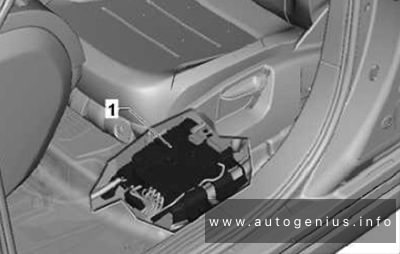
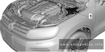
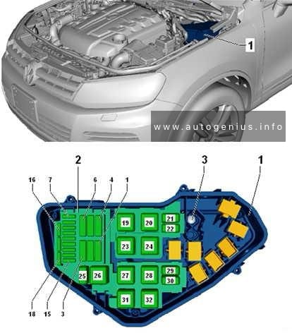
Location

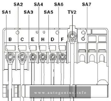
- Fuses on fuse holder A -SA- (On the electronics box, on left in engine compartment)
- Fuses on fuse holder B -SB- (On left in engine compartment)
- Fuses on fuse holder C -SC- (Under left dash panel)
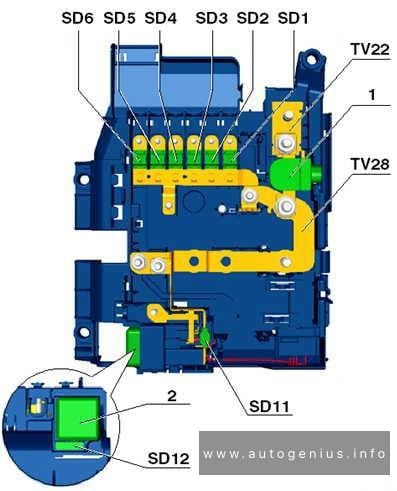
Engine Compartment
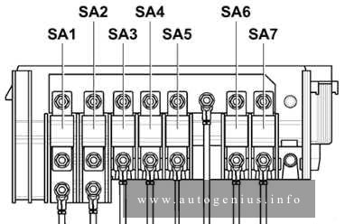
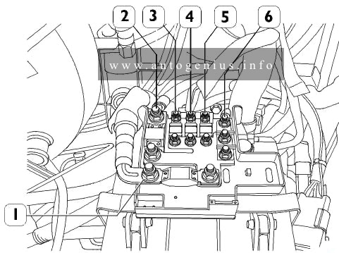
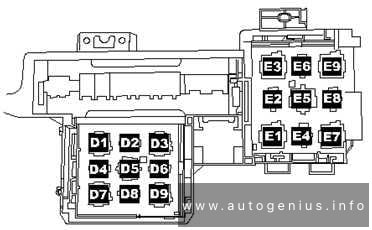
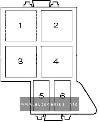
Fitting location of fuse holder A (A -SA-)
Fuse box diagram
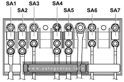
Assignment of the fuses in the engine compartment (pre-fuse box)
| No. | A | Function/component |
| 1 | 150 | Alternator -C- 90A / 110A |
| 1 | 200 | Alternator -C- 140A |
| 2 | 80 | Power steering control module -J500- Electromechanical power steering motor -V187- |
| 3 | 80 | Radiator fan control unit -J293- Radiator fan -V7- Radiator fan on right of radiator -V35- |
| 4 | 70 | Onboard supply control unit -J519- X-contact relief relay -J59- Fuse 7 on fuse holder -SC7- Fuse 8 on fuse holder -SC8- Fuse 28 on fuse holder -SC28- to -SC35- |
| 5 | – | Not used |
| 6 | 100 | Fuses on fuse holder C -SC- Fuse 20 on fuse holder -SC20- to -SC24- Fuse 42 on fuse holder -SC42- to -SC56- |
| 7 | 50 | Fuses on fuse holder C -SC- Fuse 39 on fuse holder -SC39- to -SC41- |
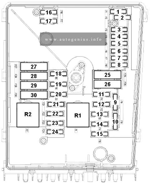
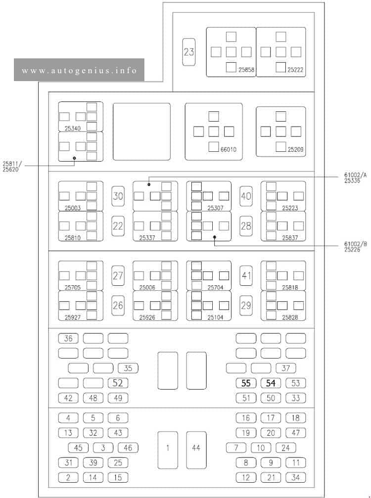
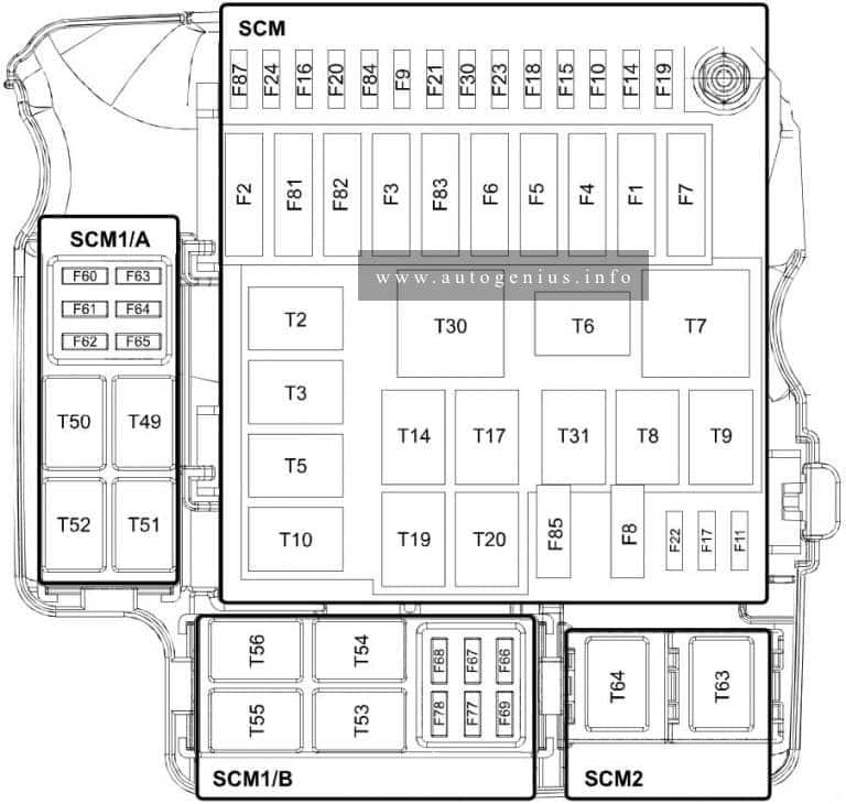
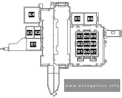
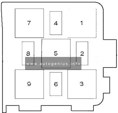
Fitting location of E-box high fuse holder (B -SB-)
Fuse box diagram
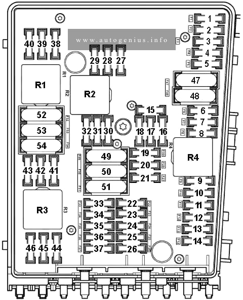
Assignment of the fuses in the engine compartment
| No. | A | Function/component |
| 1 | 30 | ABS Control Module -J104- |
| 2 | 30 | ABS Control Module -J104- |
| 3 | – | Not used |
| 4 | 5 | Onboard supply control unit -J519- |
| 5 | 20 | Onboard supply control unit -J519- Double-tone horn relay -J4- , Signal horn relay -J413- Treble horn -H2- Bass horn -H7- |
| 6 | 20 | Ignition coil 1 with output stage -N70- Ignition coil 2 with output stage -N127- Ignition coil 3 with output stage -N291- Ignition coil 4 with output stage -N292- Ignition transformer -N152- |
| 7 | 5 | Brake pedal switch -F47- J…-Engine Control Modules Clutch position sender -G476- |
| 8 | 10 | Exhaust gas recirculation valve -N18- Activated charcoal filter solenoid valve 1 -N80- Variable intake manifold changeover valve -N156- Protective resistor -N235- Radiator fan control unit -J293- Intake manifold flap motor -V157- |
| 9 | 10 | Fuel pump relay -J17- (BDJ, BJB) Glow plug relay -J52- (BDJ) Automatic glow period control module -J79- (BJB) |
| 10 | 10 | Exhaust gas recirculation valve -N18- Charge pressure control solenoid valve -N75- Exhaust gas recirculation fan switch-over valve -N345- |
| 11 | 25 | Motronic Control Module -J220- (BCA) Simos Control Module -J361- (BGU, BSE, BSF) |
| 11 | 30 | Diesel direct injection system control module -J248- (BDJ, BJB) |
| 12 | 15 | Lambda probe -G39- (BCA) Lambda probe after catalytic converter -G130- (BCA) |
| 13 | – | Not used |
| 14 | – | Not used |
| 15 | 25 | Starter -B- |
| 16 | 15 | Steering column electronics control module -J527- |
| 17 | 10 | Control unit in dash panel insert -J285- |
| 18 | – | Not used |
| 19 | 15 | Control module with display for radio and navigation system -J503- Radio -R- |
| 20 | 10 | Mobile telephone operating electronics control module -J412- |
| 21 | – | Not used |
| 22 | – | Not used |
| 23 | – | Not used |
| 24 | 10 | Data bus diagnostic interface -J533- |
| 25 | – | Not used |
| 26 | 5 | Terminal 30 voltage supply relay -J317- (BDJ, BJB ) |
| 26 | 10 | Motronic control module -J220- (BCA) |
| 27 | 10 | Heater element for crankcase breather -N79- |
| 28 | – | Not used |
| 29 | 20 | Cylinder 1 injector -N30- (BCA) Cylinder 2 injector -N31- (BCA) Cylinder 3 injector – N32- (BCA) Cylinder 4 injector -N33- (BCA) |
| 30 | 20 | Auxiliary heater control unit -J364- |
| 31 | 30 | Windscreen wiper motor -V- |
| 32 | 10 | Cylinder 1 injector -N30- (BGU) Cylinder 2 injector -N31- (BGU) Cylinder 3 injector -N32- (BGU) Cylinder 4 injector -N33- (BGU) |
| 32 | 40 | Glow plug 1 -Q10- (BDJ) Glow plug 2 -Q11- |
| 33 | 15 | Fuel pump -G6- (BCA, BGU) |
| 33 | 40 | Glow plug 3 -Q12- (BDJ) Glow plug 4 -Q13- |
| 34 | – | Not used |
| 34 | – | Not used |
| 35 | – | Not used |
| 36 | – | Not used |
| 37 | – | Not used |
| 38 | 10 | Headlight range control regulator -E102- Left headlamp levelling actuator -V48- Right headlamp levelling actuator -V49- |
| 39 | 5 | Oil level and oil temperature sensor -G266- Control unit in dash panel insert -J285- |
| 40 | 20 | Fuses on fuse holder C -SC- Fuse 1 on fuse holder -SC1- to -SC6- Fuse 9 on fuse holder -SC9- to -SC16- Fuse 25 on fuse holder -SC25- to -SC27- |
| 41 | – | Not used |
| 42 | 5 | Fuel pump relay -J17- (BCA, BGU) |
| 42 | 10 | Air mass meter -G70- (BJB) |
| 43 | – | Not used |
| 44 | – | Not used |
| 45 | 15 | Lambda probe -G39- (BGU) Lambda probe after catalytic converter -G130- (BGU) |
| 46 | – | Not used |
| 47 | 40 | Onboard supply control unit -J519- , left headlight |
| 48 | 40 | Onboard supply control unit -J519- , right headlight |
| 49 | – | Not used |
| 50 | – | Not used |
| 51 | 40 | Secondary air pump relay -J299- (BGU) Secondary air pump motor -V101- |
| 51 | 50 | Automatic glow period control module -J179- (BJB) Glow plug 1 -Q10- Glow plug 2 -Q11- Glow plug 3 -Q12- Glow plug 4 -Q13- |
| 52 | – | Not used |
| 53 | 25 | Driver door control unit -J386- Front passenger door control unit -J387- |
| 54 | 50 | Radiator fan control unit -J293- Radiator fan -V7- Right fan for coolant -V35- Radiator fan thermal switch -F18- Radiator fan -V7- |
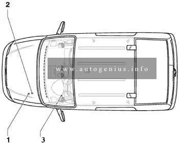
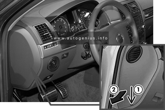
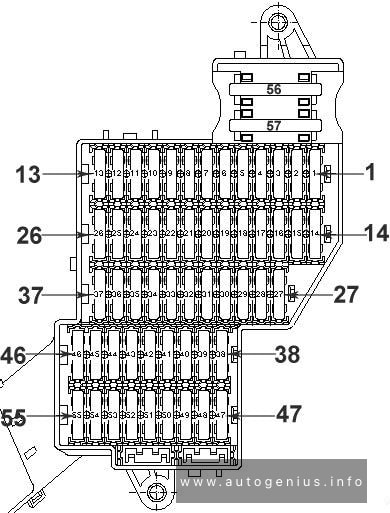
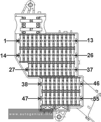
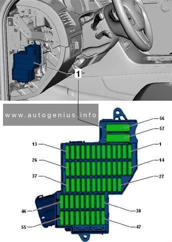
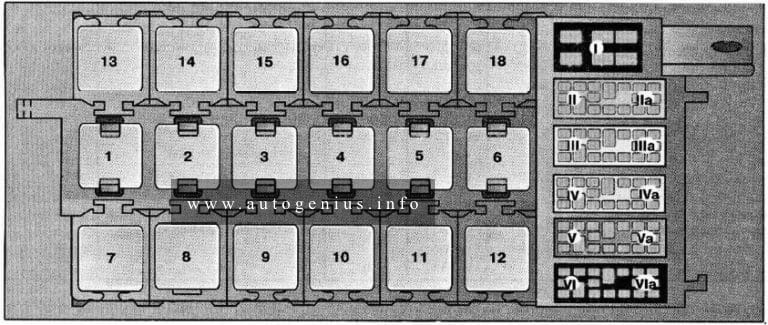
Passenger Comparment
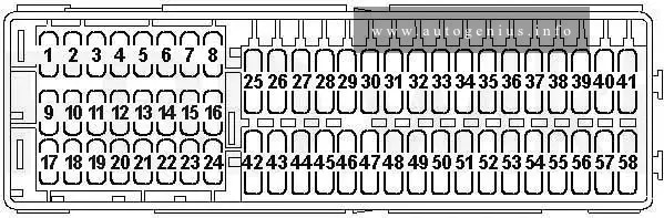
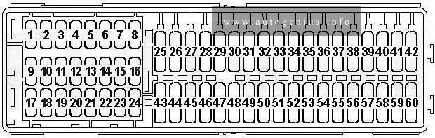
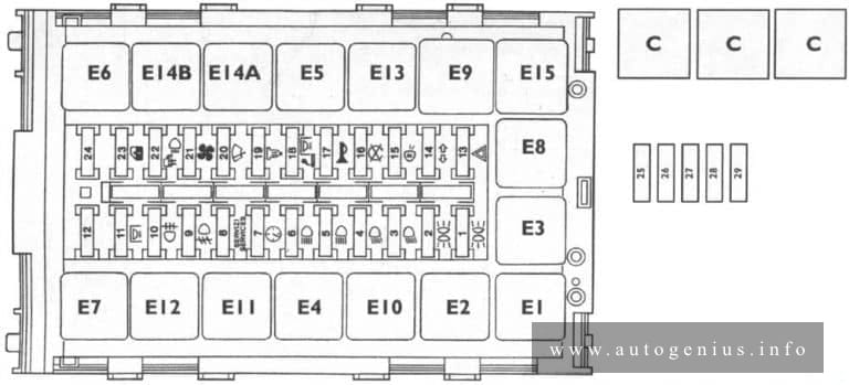
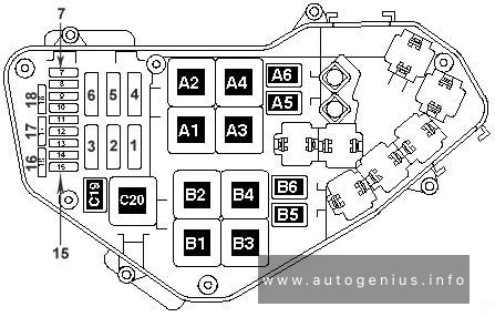
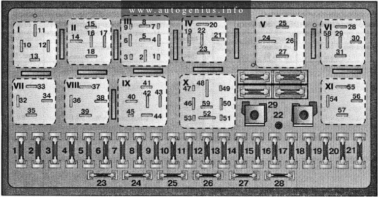
Position of fuses on fuse holder C -SC-
Fuse box diagram

Assignment of the fuses in the engine compartment
| No. | A | Function/component |
| 1 | – | Not used |
| 2 | 5 | Trailer detector control unit -J345- |
| 3 | 5 | Heater/heat output switch -E16- High pressure sender -G65- |
| 4 | – | Not used |
| 5 | – | Not used |
| 6 | – | Not used |
| 7 | 5 | Heated driver seat regulator -E94- Heated front passenger seat regulator -E95- |
| 8 | 5 | Left washer jet heater element -Z20- Right washer jet heater element -Z21- |
| 9 | 5 | Airbag control unit -J234- Front passenger side airbag deactivated warning lamp -K145- |
| 10 | 5 | Mobile telephone operating electronics control unit -J412- |
| 11 | 10 | Power steering control unit -J500- |
| 12 | – | Not used |
| 13 | – | Not used |
| 14 | 5 | Traction control system switch -E132- TCS and ESP button -E256- ABS control unit -J104- |
| 15 | 10 | Reversing light switch -F4- Auxiliary heater operation relay -J485- (from May 2004) Control unit with display for radio and navigation system -J503- (commercial equipment) T16 – Self-diagnosis connection (T16/1) |
| 16 | 5 | Data bus diagnostic interface -J533- |
| 17 | 7.5 | Left tail light and rear fog light bulb -M41- (models without central locking) |
| 18 | – | Not used |
| 19 | – | Not used |
| 20 | – | Not used |
| 21 | – | Not used |
| 22 | 5 | Remote control receiver for auxiliary coolant heater -R149- |
| 23 | 10 | Brake light switch -F- Left brake light bulb -M9- Right brake light bulb -M10- High level brake light bulb -M25- ABS control unit -J104- |
| 24 | 10 | Light switch -E1- Air conditioning system control unit -J301- 16-pin connector -T16- (self-diagnosis connection T16/16) |
| 25 | 30 | Heated driver seat control unit -J131- Heated front passenger seat control unit -J132- |
| 26 | 10 | J… – Engine control units |
| 27 | 15 | Rear window wiper motor -V12- (from May 2004) |
| 28 | 5 20 |
Light switch -E1- (models with central locking) Fog light switch -E7- (models without central locking) Rear fog light switch -E18- (models without central locking) |
| 29 | 15 | Rear window wiper motor -V12- (up to April 2004) |
| 30 | 25 | Light switch -E1- (models without central locking) Fuse 37 on fuse holder C -SC37- Fuse 38 on fuse holder C -SC38- |
| 31 | 15 | Auxiliary heater operation relay -J485- (up to April 2004) |
| 32 | 15 | Washer pump -V5- |
| 33 | – | Not used |
| 34 | – | Not used |
| 35 | 40 | Fresh air blower -V2- Auxiliary heater operation relay -J485- |
| 36 | – | Not used |
| 37 | 15 | Right dipped beam bulb -M31- (models without central locking) |
| 38 | 15 | Left dipped beam bulb -M29- (models without central locking only) |
| 39 | – | Not used |
| 40 | 20 | Trailer detector control unit -J345- |
| 41 | 20 | Trailer socket -U10- |
| 42 | 15 30 |
12 V socket -U5- (near handbrake lever) 12 V socket 2 -U18- (left luggage compartment) |
| 43 | 15 | Electric fuel pump 2 relay -J49- (BCA, BGU) Fuel pump relay -J17- (BDJ, BJB) Fuel system pressurisation pump -G6- |
| 44 | 5 | Interior monitoring sensor -G273- Vehicle inclination sender -G384- Alarm horn -H12- |
| 45 | 5 | Aerial selection control unit -J515- |
| 46 | 7.5 | Onboard supply control unit -J519- (Interior light) |
| 47 | 25 30 |
Cigarette lighter -U1- Rear cigarette lighter -U9- |
| 48 | 20 | Headlight washer system relay -J39- Headlight washer system pump -V11- |
| 49 | 10 | Driver door control unit -J386- Front passenger door control unit -J387- |
| 50 | – | Not used |
| 51 | – | Not used |
| 52 | 25 | Fresh air blower relay -J13- Onboard supply control unit -J519- |
| 53 | 25 | Convenience system central control unit -J393- |
| 54 | – | Not used |
| 55 | – | Not used |
| 56 | – | Not used |
| 57 | – | Not used |
| 58 | – | Not used |
There are also videos on this topic on our YouTube channel.
WARNING: Terminal and harness assignments for individual connectors will vary depending on vehicle equipment level, model, and market.