Volkswagen Caddy (III; 2010 – 2015) – fuse and relay box diagram

Volkswagen Caddy (III; 2010 – 2015) – fuse and relay  box diagram

Year of production: 2010, 2011, 2012, 2013, 2014, 2015


In this article, we take a look at the third-generation  Volkswagen Caddy (2K) before its first facelift, produced between 2003 and 2010. You will find fuse box diagrams for the 2010 – 2015 models, along with details on the location of the fuse panels inside the vehicle and the assignment of each fuse (fuse layout).


Location

Volkswagen Caddy (III; 2010 – 2015) – fuse box location


  1. Fuses on fuse holder A -SA- (On the electronics box, on left in engine compartment)
  2. Fuses on fuse holder B -SB- (On left in engine compartment)
  3. Fuses on fuse holder C -SC- (Under left dash panel)
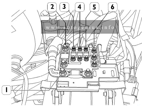
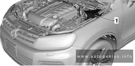
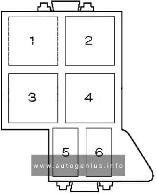
Engine Compartment

Fitting location of fuse holder A (A -SA-)

Fuse box diagram

Volkswagen Caddy (III; 2010 - 2015) - fuse box diagram - fitting location of fuse holder A (A -SA-)
Volkswagen Caddy (III; 2010 – 2015) – fuse box diagram – fitting location of fuse holder A (A -SA-)


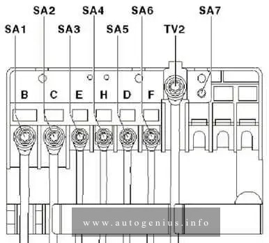
Assignment of the fuses in the engine compartment (pre-fuse box)

No.
A
Function/component
1 150 Alternator -C-
200 Alternator -C-1)
2 80 Power steering control unit -J500-
Electromechanical power steering motor -V187-
3 50 Radiator fan control unit -J293-
4 80 X-contact relief relay -J59-

t Fuse holder C -SC- (-SC28- up to -SC33- )
5 80 Fuse holder C -SC- (-SC20- up to -SC24- and -SC43- up to -SC53- )
6 40 Low heat output relay -J359-
7 80 High heat output relay -J360-
1) Models with 140 A generator only

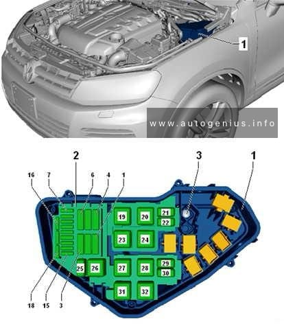
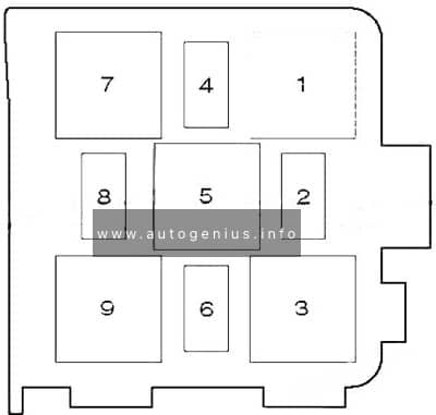
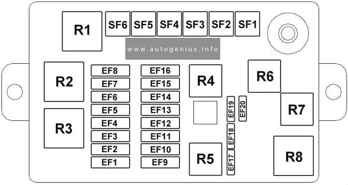
Fitting location of E-box high fuse holder (B -SB-)

Fuse box diagram

Volkswagen Caddy (III; 2010 - 2015) - fuse box diagram - engine compartment (holder B -SB-)
Volkswagen Caddy (III; 2010 – 2015) – fuse box diagram – engine compartment (holder B -SB-)


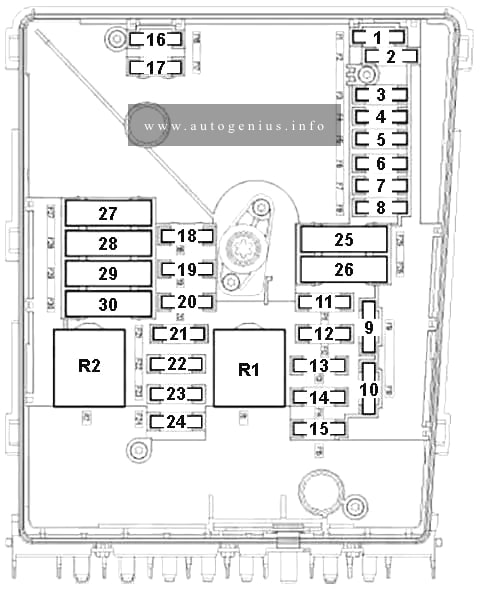
Assignment of the fuses in the engine compartment (holder B)

No.
A
Function/component
1
2 30 Mechatronic unit for dual clutch gearbox -J743-
3 5 Battery monitoring control unit -J367-
Onboard supply control unit -J519- (T52a/24)
4 20 ABS control unit -J104-
ABS hydraulic unit -N55-
5 15 Mechatronic unit for dual clutch gearbox -J743-
6 5 Control unit in dash panel insert -J285-
Steering column electronics control unit -J527-
7 40 Terminal 15 voltage supply relay -J329-
Fuse holder C -SC- (-SC9- up to -SC16- and -SC25- up to -SC27- )
8 15 Control unit with display for radio and navigation -J503-
Radio -R-
Voltage stabiliser -J532-3)
Control module with display unit for radio and navigation system -J503-
Radio -R-
Fuse 57 on fuse holder C -SC57-
Fuse 58 on fuse holder C -SC58-
9 5 Mobile telephone operating electronics control unit -J412-4)
10 5 Main relay -J271-
Engine control unit -J623-
Engine component current supply relay -J757-
11 30 Auxiliary heater control unit -J364-
12 5 Data bus diagnostic interface -J533-
13 15 Engine control unit -J623- (petrol engine)
30 Engine control unit -J623- (diesel engine)
14 15 Fuel pressure regulating valve -N276- (diesel engine)
Fuel metering valve -N290- (diesel engine)
20 Ignition transformer -N152-
Ignition coil 1 with output stage -N70-
Ignition coil 2 with output stage -N127-
Ignition coil 3 with output stage -N291-
Ignition coil 4 with output stage -N292-
15 5 Low heat output relay -J359- (diesel engine)
High heat output relay -J360- (diesel engine)
Fuel pump relay -N17-
Electric fuel pump 2 relay -J49-
Automatic glow period control unit -J179-
10 Lambda probe heater -Z19-
Lambda probe 1 heater after catalytic converter -Z29-
Low heat output relay -J359-
High heat output relay -J360-
Fuel pump switch-off relay -J333-2)
Gas injection valve 1 -N366-1)
Gas injection valve 2 -N367-1)
Gas injection valve 3 -N368-1)
Gas injection valve 4 -N369-1)
15 High-pressure valve for gas mode -N372-2)
Valve for gas tank -N495-2)
Sensor for gas level gauge -G707-2)
Gas injection valve 1 -N366-2)
Gas injection valve 2 -N367-2)
Gas injection valve 3 -N368-2)
Gas injection valve 4 -N369-2)
16 30 Onboard supply control unit -J519- (T52c/42)
Light bulb for right foglamp -L23-
Right cornering light bulb -L149-
Rear left fog light bulb -L46- , or rear right fog light bulb -L47-
Right daytime running light bulb -L175-
Left side light bulb -M1-
Right tail light bulb -M2-
Rear left turn signal bulb -M6-
Front right turn signal bulb -M7-
Left brake light bulb -M9-
Right reversing light bulb -M17-
Left turn signal repeater bulb -M18-
High-mounted brake light bulb -M25-
Right headlight dipped beam bulb -M31-
Right headlight main beam bulb -M32-
17 15 Horn relay -J413-
18 30 Special vehicle control unit -J608-
19 30 Wiper motor control unit -J400-
20 10 Fuel tank shut-off valve 1 -N361-1)
Fuel tank shut-off valve 2 -N362-1)
Fuel tank shut-off valve 3 -N363-1)
Fuel tank shut-off valve 4 -N429-1)
Fuel tank shut-off valve 5 -N430-1)
Coolant circulation pump -V50-
21 10 Lambda probe heater -Z19- (diesel engine)
15 Fuel pump control unit -J538-
Lambda probe heater -Z19-
Lambda probe 1 heater after catalytic converter -Z29-
22 5 Clutch position sender -G476-
Brake light switch -F-5)
23 5 Additional coolant pump relay -J496-
10 Air mass meter -G70- (Diesel engine)
Charge pressure control solenoid valve -N75- (Diesel engine)
Exhaust gas recirculation cooler changeover valve -N345- (Diesel engine)
Control unit for gas mode -J659-
Relay for gas shut-off valves -J908-1)
High-pressure valve for gas mode -N372-1)
15 Fuel pressure regulating valve -N276-
24 10 Radiator fan control unit -J293-
Secondary air pump relay -J299-
Additional coolant pump relay -J496-
Activated charcoal filter solenoid valve 1 -N80-
Coolant regulating valve -N515-
Variable intake manifold changeover valve -N156-
Coolant circulation pump 2 -V178-
Injector, cylinder 1 -N30-1)
Injector, cylinder 2 -N31-1)
Injector, cylinder 3 -N32-1)
Injector, cylinder 4 -N33-1)
25 40 ABS hydraulic pump -V64-
ABS control unit -J104-
26 30 Onboard supply control unit -J519- (T52a/1)
Left cornering light bulb -L148-
Left fog light bulb -L22-
Rear left fog light bulb -L46- , or rear right fog light bulb -L47-
Left daytime running light bulb -L174-
Right side light bulb -M3-
Left tail light bulb -M4-
Front left turn signal bulb -M5-
Rear right turn signal bulb -M8-
Right brake light bulb -M10-
Left reversing light bulb -M16-
Right turn signal repeater bulb -M19-
Left headlight dipped beam bulb -M29-
Left headlight main beam bulb -M30-
27 40 Secondary air pump motor -V101-
50 Automatic glow period control unit -J179-
28
29 30 Fuse 18 on fuse holder C -SC18-
Fuse 19 on fuse holder C -SC19-
50 Fuse 35 on fuse holder C -SC35-
Fuse 39 on fuse holder C -SC39-
Fuse 54 on fuse holder C -SC54-
Fuse 55 on fuse holder C -SC55-
Fuse 59 on fuse holder C -SC59-
Fuse 60 on fuse holder C -SC60-
30 50 Fuse holder C -SC- (-SC40- up to -SC42- )
1) for vehicles with engine code BSX only
2) for vehicles with engine code CHGA only
3) for vehicles with start/stop system only
4) for vehicles without start/stop system only
5) effective since November 2011

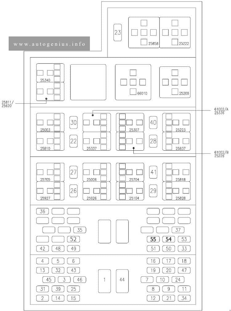
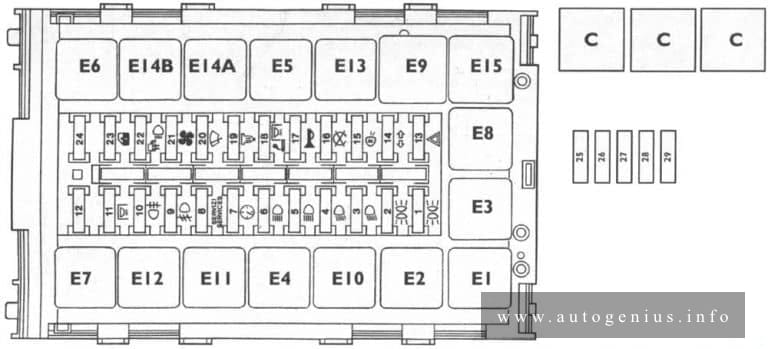
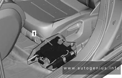
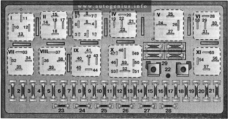
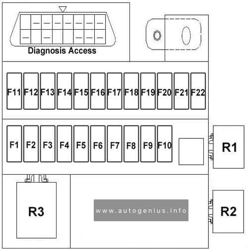
Passenger Comparment

Position of fuses on fuse holder C -SC-

Fuse box diagram

Volkswagen Caddy (III; 2010 - 2015) - fuse box diagram - passenger compartment (holder C -SC-)
Volkswagen Caddy (III; 2010 – 2015) – fuse box diagram – passenger compartment (holder C -SC-)


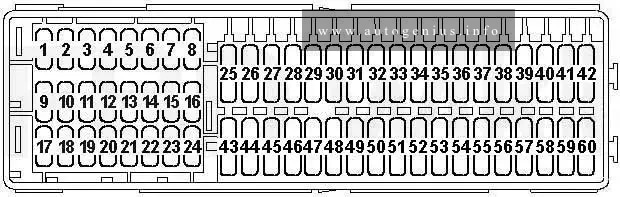
Assignment of the fuses in the passenger compartment (holder C)

No.
A
Function/component
1
2
3
4
5
6
7
8
9 10 -Special vehicles-
4-pin connector -T4aa- , Pin 1 3)
10-pin connector -T10l- , Pin 4 (Interface for special functions)
10 5 Fuel pump relay -J17-
Main relay -J271-
Gas mode control unit -J659-
Terminal 50 voltage supply relay -J682-
Starter relay 1 -J906-
Voltage stabiliser -J532-
Data bus diagnostic interface -J533-
Engine control unit -J623-
11 5 Parking aid control unit -J446-
Park assist steering control unit -J791-
12 5 -Special vehicles-
Taximeter -G41-
Mirror taximeter -G511-
103) -Special vehicles-3)
2-pin connector -T2ab- , Pin 1
2-pin connector -T2ac- , Pin 1
28-pin connector -T28b- , Pin 13
204) -Special vehicles-4)
8-pin connector -T8k- , Pin 8
28-pin connector -T28a- , Pin 20
28-pin connector -T28b- , Pin 20
13 7.5 Brake light switch -F-3)
Headlight range control adjuster -E102-
TCS and ESP button -E256-
Tyre pressure monitor display button -E492-
Start/Stop operation button -E693-
ABS control unit -J104-
Trailer detector control unit -J345-
All-wheel drive control unit -J492-
Power steering control unit -J500-
Selector lever sensors control unit -J587-
Mechatronic unit for dual clutch gearbox -J743-
Left headlight range control motor -V48-
Right headlight range control motor -V49-
Control unit for cornering light and headlight range control -J745-
14 10 Reversing light switch -F4-
Air mass meter -G70-
Auxiliary heater operation relay -J485-
Control unit in dash panel insert -J285-
Heater element for crankcase breather -N79-
Activated charcoal filter solenoid valve 1 -N80-
Diagnostic connection -U31-16-pin connector -T16- , Pin 1
15 5 Airbag control unit -J234-
Front passenger side airbag deactivated warning lamp -K145-
16 5 Light switch -E1-
Heater/heat output switch -E16-
High-pressure sender -G65-
Air quality sensor -G238-
Oil level and oil temperature sender -G266-
Automatic anti-dazzle interior mirror -Y7-
17
18 10 -Special vehicles-
Taxi alarm remote control control unit -J601-
10 -Special vehicles-
10-pin connector -T10l- , Pin 6 (Interface for special functions)
19 10 -Special vehicles-
Taximeter -G41-
Mirror taximeter -G511-
Taxi alarm remote control control unit -J601-
Two-way radio -R8-
Printer -R98-
10 -Special vehicles-
10-pin connector -T10l- , Pin 7 (Interface for special functions)
20 20 Cigarette lighter -U1-7)
21 10 Light switch -E1-
Heater/heat output switch -E16-
Rain and light sensor -G397-
Heated rear window relay -J9-
Climatronic control unit -J255-
Air conditioning system control unit -J301-
Horn relay -J413-
Remote control receiver for auxiliary coolant heater -R149-
Selector lever sensors control unit -J587-
Diagnostic connection -U31-16-pin connector -T16- , Pin 16
Switch for interior lighting -E599- (Camper)
Rear interior light -W43- (Camper)
22 10 Onboard supply control unit -J519- (T52b/42) 2)
23 5 -Special vehicles-
Interior light switch (taxi) -E115-
Taxi sign switch -E138-
10-pin connector -T10l- , Pin 1 (Interface for special functions)
10 -Special vehicles-
3-pin connector -T3ak- , Pin 1 3)
  Flashing lights relay -J630-4)
24 5 Interior monitoring sensor -G273-
Vehicle inclination sender -G384-
Anti-theft alarm sensor -G578-
Alarm horn -H12-
Onboard supply control unit -J519- (T52c/1)
25 10 Output module for left headlight -J667-
26 10 Output module for right headlight -J668-
27
28 20 12-V socket 3 -U19- , in storage compart.
29 15 Rear window wiper motor -V12-
30
31 5 Heater/heat output switch -E16-
Left washer jet heater element -Z20-
Right washer jet heater element -Z21-
32
33 40 Air conditioning system control unit -J301-
Heater/heat output switch -E16-
34
35 10 -Special vehicles-3)
Fluorescent light in rear of high roof -W41-
Fluorescent light in centre of high roof -W42-
36
37
38
39 20 -Special vehicles-
10-pin connector -T10ai- , Pin 1 3)
30 -Special vehicles-
4-pin connector -T4ad- , Pin 1 4)
40 20 Trailer detector control unit -J345-
41 20 Trailer detector control unit -J345-
42 20 Trailer detector control unit -J345-
43 15 Fuel pump relay -J17-
Electric fuel pump 2 relay -J49-
Supplementary fuel pump -V393-
44 40 Fresh air blower control unit -J126-
Fresh air blower -V2-
45 20 Headlight washer system relay -J39-
Headlight washer system pump -V11-
46 10 Onboard supply control unit -J519- (T52b/42) 1)
Front interior light -W1-
Luggage compartment light -W3-
Glove compartment light -W6-
Rear interior light -W43-
30 Driver door control unit -J386-2)
47 30 Cigarette lighter -U1-6)
X-contact relief relay -J59-7)8)
Fuse holder C -SC- (-SC28- up to -SC33- ) 7)8)
48 30 Heated front seats control unit -J774-
49 30 Driver door control unit -J386-1)
Front passenger door control unit -J387-
50 20 Onboard supply control unit -J519- (T52b/1)
Rear window wiper motor -V12-
Windscreen and rear window washer pump -V59-
Washer pump -V5-
51 15 Trailer voltage supply relay -J941-
Trailer socket -U10- (T13/10)
30 -Special vehicles-
10-pin connector -T10ai- , Pin 4
10-pin connector -T10ai- , Pin 5
52 25 Heated rear window relay -J9-
Heated rear window -Z1-
Heated rear window in left wing door -Z26-
Heated rear window in right wing door -Z27-
Fresh air blower relay -J13-
Fresh air blower series resistor with overheating fuse -N24-
Fresh air blower -V2-
53 156)
207)
12 V socket -U5- , in the rear centre console
12 V socket 2 -U18- , In rear left side panel
54 15 -Special vehicles-4)
Switch-over relay 1 for roof ventilator -J180-
55 15 -Special vehicles-4)
8-pin connector -T8m- , Pin 4
8-pin connector -T8n- , Pin 4
56
57 5 Control unit in dash panel insert -J285-5)
Steering column electronics control unit -J527-5)
58 5 Mobile telephone operating electronics control unit -J412-5)
59 5 -Special vehicles-
Radio switch -E72-
Ignition bypass button -E489-
Button for daytime running light switch-off -E652-
Accident data memory -J754-
60 30 -Special vehicles-
3-pin connector -T3al- , Pin 1
1) before April 2011
2) after May 2011
3) before October 2011
4) after November 2011
5) for vehicles with start-stop system only
6) before October 2012
7) after November 2012
8) for vehicles with Climatronic only

WARNING: Terminal and harness assignments for individual connectors will vary depending on vehicle equipment level, model, and market.

Iveco Daily (III; 2000 – 2006) – fuse and relay box diagram

Iveco Daily (III; 2000 – 2006) – fuse and relay box diagram


Year of production: 2000, 2001, 2002, 2003, 2004, 2005, 2006


This article covers the second-generation Iveco Daily (III), produced from 2000 to 2006. It includes fuse box diagrams for the 2000, 2001, 2002, 2003, 2004, 2005 and 2006 models, provides details on the location of the fuse panels inside the vehicle, and explains the function and layout of each fuse.

Passenger compartment

Fuse box diagram

Iveco Daily(III; 2000 - 2006) - fuse and relay box diagram - passenger compartment
Iveco Daily(III; 2000 – 2006) – fuse and relay box diagram – passenger compartment


Assignment of the fuses in the passenger compartment

No Function A
1 ID/TCA (.11): Thermal starter 40
1 UNIJET (.13-.15): Thermal starter 80
1 UNIJET F1A (.10-.12): Thermal starter, additional heater 30
2 Immobilizer/Warming/EDC 5
3 DDS device 5
4 Instrument cluster (+30) 5
5 Instrument cluster (+15) 5
6 Stalk unit (rear fog guard, flasher) 5
7 Stalk unit (low beams) 10
8 Stalk unit (high beams) 15
9 Stalk unit (side lights) 15
10 Windscreen wiper 15
11 Stalk unit (direction indicators/hazard warning lights) 15
12 Stalk unit (horns) 15
13 Reversing light 5
14 Side light, clearance, no. plate light 5
15 Side light cluster lighting 5
16 Left low beam headlamp 10
17 Right low beam headlamp 10
18 Left high beam headlamp 10
19 Right high beam headlamp/headlamp aming 10
20 Interior lighting/radio/cigar lighter 10
20 UNIJET F1A (.10-.12): Interior lighting/radio 10
21 Electric windscreen defrosting unit 30
21 UNIJET F1A (.10-.12): Cigar lighter 15
22 Heated fuel filter 15
23 EDC electronic control unit 25
24 EDC 10
25 Stop lights 5
26 13-pin current socket 15
27 13-pin current socket 15
28 13-pin current socket 10
29 38-pin diagnostic connector 5
30 Fog lamps 10
31 Climate control, additional heater, engine cooling 5
31 UNIJET F1A (.10-.12): Compressor, timer, engine fan 10
32 Climate control 5
33 Additional heater 20
34 Headlamp washer 20
35 Rear differential lock 5
36 ABS, EBD, ABD failure warning light 5
37 ABS 5
39 Heated mirrors 10
39 UNIJET F1A (.10-.12): Heated mirrors, heated rear-screen, heated windscreen 10
40 Power windows 30
40 UNIJET F1A (.10-.12): Power windows (left) 20
41 Heated rear-screen, heated windscreen 10/ 20
42 Self-levelling suspensions (Wabco) 5
43 Air bag failure warning light 5
44 Self-levelling suspensions (Wabco) 40
45 Air-bag 5
46 Solenoid valve for thermal starter 5
46 UNIJET F1A (.10-.12): Power windows (right) 20
47 Electric fuel pump 10
48 Door locking/alarm 30
49 Door locking/alarm 5
50 Rear differential lock 30
51 Total power takeoff 10
52 Front differential lock (4×4) 30
53 Self-levelling suspensions Techniek) 30
54 Electric hatch (van and 6+1) 15
55 Rototranslating door 15
Code Relays
25035 Switching on external lights
25003 Switching on fog lamps
25006 Switching on stop lights
25704 Total power takeoff engagement control
25104 Switching off Retarder with ABS on
25209 Loads cut-off during starting
25222 Thermal starter engagement enable
25223 Thermal starter fan control
25307 Climate control compressor engagement
25336 Engine cooling
25337 Climate control compressor disengagement
25340 Compressor on signal
25620 Fuel filter clogged signal
25705 Diagnostics enable
25810 Heated fuel filter circuit control
25811 Advance variator control (KSB)
25818 Heated windscreen switching on
25837 Electric fuel pump switching on
25858 EDC switching on
25926 Suspension raising enable
25927 Suspension lowering enable
25928 Rear-screen heating switching on
61002A Anti-retum from Trinary
61002В Anti-retum from TGC (bus)
66010 Timer for headlamp washer
WARNING: Terminal and harness assignments for individual connectors will vary depending on vehicle equipment level, model, and market.

Iveco Daily (V; 2011 – 2014) – fuse and relay box diagram

Iveco Daily (V; 2011 – 2014) – fuse and relay box diagram

Year of production: 2011, 2012, 2013, 2014


This article covers the second-generation  Iveco Daily V (5th generation), produced from 2011 to 2014. It includes fuse box diagrams for the 2011, 2012, 2013 and 2014 models, provides details on the location of the fuse panels inside the vehicle, and explains the function and layout of each fuse.

Passenger compartment (under the dashboard)

Fuse box diagram

Iveco Daily (V; 2011 - 2014) - fuse and relay box doagram - passenger compartment
Iveco Daily (V; 2011 – 2014) – fuse and relay box doagram – passenger compartment


Assignment of the fuses in the passenger compartment (under the dashboard)

No Function A
F12 Т1b relay (30-87) for right low beam headlight 7,5
F13 T1a relay (30-87) for left low beam headlight – headlight adjuster 7,5
F31 T54 relay (86) for headlight washers and T50 – T51 – T52 – T53 – eln motors and controls for electric windows 5
F32 T44 relay (30-86) for battery removal with minimum voltage – internal lighting 7,5
F33 Ooutswinging door 15
F34 Fitter socket 20
F36 T20 relay for MODUS car radio – tachograph – convergence – siren – parking sensor 15
F37 Instrument panel – stop lights – trailer socket 7,5
F38 Central locking 20
F42 ABS9 or ESP9 5
F43 T23a relay (86-87) for windscreen washer and T23b relay (86-87) 20
F47 T25a relay (86-87) and T25b (86-87) for driver’s side electric window 25
F48 T26a relay (86-87) and T26b (86-87) for passenger side electric window 25
F49 Control panel – tachograph – exp. module – fitter socket – ASR control – Telma (coil) – video camera – outswinging – rear differential lock 5
F50 Airbag 5
F51 Green filter – car radio – toe-in – parking sensors -CAF 5
F53 Instrument panel – timer for supplementary heater 5
F89 AVAILABLE
F90 T11a relay (30-86) for left full beam headlight 7,5
F91 T11b relay (30-86) for right high beam headlight 7,5
F92 T12a relay (30-86) for left foglight 7,5
F93 T12b relay (30-86) for right foglight 7,5
No. Relays
T01а Left low beam headlight – headlight adjuster
T01b Right low beam headlight
Т11а Left high beam headlight
T11b Right high beam headlight
Т12а Left foglight
Т12b Right foglight
Т23а Windscreen washer
Т25а Driver’s side electric window UP
Т25b Driver’s side electric window DOWN
Т26а Passenger side electric window UP
Т26b Passenger side electric window DOWN
Т37а Rear doors central closing
Т37b Central closing (common)
Т37с Side doors central closing
T37d Rear door central closing
Т44 Battery removal with minimum voltage

Engine compartment (Fuse box above the battery)

Fuse box diagram

Iveco Daily (V; 2011 - 2014) - fuse and relay box doagram - engine compartment (above the battery)
Iveco Daily (V; 2011 – 2014) – fuse and relay box doagram – engine compartment (above the battery)


Assignment of the fuses in the engine compartment (above the battery)

No Function A
1 +30 positive from F75 for starter motor, alternator and retarder (if present) 500
2 +30 positive from F70 for SCM BUS-BAR 150
3 +30 positive from F73 for pre-heating glow plugs 60
4 +30 positive from F72 for braking node 40
5 +30 positive from F7I for Ist Body Computer power 80
6 +30 positive to F64 in SCM/A for IBS sensor for Stop & Start

Engine compartment

Fuse box diagram

Iveco Daily (V; 2011 - 2014) - fuse and relay box doagram - engine compartment
Iveco Daily (V; 2011 – 2014) – fuse and relay box doagram – engine compartment


Assignment of the fuses in the engine compartment

No Function A
F01 Air suspensions 40
F02 Ignition switch 30
F03 Cab climate control fans and engine coolant supplementary heater 40
F04 Braking system (valves) 30
F05 Air suspensions 40
F06 SCM 1 /А – SCM 1 /В – SCM2 power supply 40
F07 T7 relay (30-87) for power discharge from ignition switch 40
F08 T8 relay (30-87) for fuel pump 15
F09 Automatic transmission 30
F11 T64 relay (30-87) for heated exterior mirrors and heated windscreen 15
F11 EDC FI A (primary loads) from MAIN RELAY injectors (CNG) 15
F14 Automatic transmission – MAIN RELAY T9 (86) 10
F15 T2 relay (30-87) for BOSCH cooling pump 10
F16 Cigarette lighter from T7 15
F17 EDC FIC (secondary loads) from MAIN RELAY Smart Drive Unit (CNG) 10/15
F18 Rear differential lock 30
F19 T6 relay (30-87) for horn 7,5
F20 13 pin socket 10
F21 TI4 relay (30) for cylinder solenoid valves (CNG) 7,5
F22 EDC F1A and F1C (primary loads) from MAIN RELAY – lambda probe 20
F22 Waste gate (CNG) – lambda probes (CNG) 15
F23 T19 relay (30-87) for wipers 30
F24 Power socket from T7 15
F30 T3 relay (30-87) for side marker lamps 7,5
F81 Automatic transmission 30
F82 Body computer 2nd power 70
F83 T30 relay (30-87) for heating fans inside cab 40
F84 Solenoid valve power for the cylinders 15
F84 T5 and T14 relays for Baruffaldi coupling 7,5
F85 T31 relay (30-87) for fuel filter and sediment filter heater 25
F87 EDC – automatic transmission 7,5
F87 5SF – automatic transmission 7,5
Relay
T02 BOSCH cooling pump 20
T02 Baruffaldi coupling from trinary (CNG) 20
Т03 Side marker lamps 30
T05 Ist gear Baruffaldi coupling 30
T06 Horn 20
T07 Power discharge from ignition switch 50
T08 Fuel pump 20
T09 MAIN RELAY 30
T10 Engine start-up prevention 30
T14 2nd gear Baruffaldi coupling 20
T14 Cylinder solenoid valves (CNG) 20
T17 Windscreen wiper 1or 2nd speed 10/20
T19 Indscreen wiper speed activation 10/20
T20 Diagnostics with MODUS 20
Т30 Cab heating fans 50
T31 Fuel filter heater and sediment filter 30
SCM1/A
F60 Supplementary climate control 30
F61 T51 relay (30-87) for air conditioner compressor 7,5
F62 T52 relay (30-87) for right heated rear window 10
F63 Left heated rear window blow-by – unit heater – T56 relay (86) for compressor 10
F64 IBS sensor for Stop & Start 5
F65 T7 relay (30-87) for heated seats 20
Relay
T49 Stop & start 30
T50 AVAILABLE
T51 Compressor activation from climate control 20
T52 Heated rear windows 20
SCM1/B
F66 T54 relay (30-87) for headlight washers 15
F67 AVAILABLE
F68 AVAILABLE
F69 Optional 4448 for bus 5
F77 AVAILABLE
F78 AVAILABLE  –
Relay
T53 Unit heater 20
T54 Headlight washers 20
T55 Power Take Off 10/20
T56 Stop lights with TELMA retarder activated 10/20
SCM2
T63 AVAILABLE
T64 External heated mirrors – heated windscreen 20

WARNING: Terminal and harness assignments for individual connectors will vary depending on vehicle equipment level, model, and market.

Iveco Daily (II; 1989 – 2000) – fuse and relay box diagram

Iveco Daily (1989 – 2000) – fuse and relay  box diagram

Year of production: 1989, 1990, 1991, 1992, 1993, 1994, 1995, 1996, 1997, 1998, 1999, 2000


This article covers the second-generation   Iveco Daily II (2nd generation), produced from 1989 to 2000. It includes fuse box diagrams for the 1989, 1990, 1991, 1992, 1993, 1994, 1995, 1996, 1997, 1998, 1999 and 2000 models, provides details on the location of the fuse panels inside the vehicle, and explains the function and layout of each fuse.

Fuse box diagram

Iveco Daily (II; 1989 - 2000) - fuse and relay box diagram
Iveco Daily (II; 1989 – 2000) – fuse and relay box diagram


Assignment of the fuses in the fuse box

No. A Function
1 5 Lh front parking light – Lh number plate light- Rh rear parking light – Rh front and Lh rear marker
2 5 lights – Dashboard. Rh front parking light – Rh number plate light -Lh rear parking light – Lh front and Rh rear
3 7,5 marker lights. Lh low beam light
4 7,5 Rh low beam light
5 7,5 Lh high beam light
6 7,5 Rh high beam light
7 3 Electronic speedometer or tachograph
8 5 Brake – instrument – telltale failure
9 10 Fog headlights
10 3 Rear fog lamps
11 5 Interior lighting (bus)
12 7,5 Not used
13 10 Hazard lights
И 5 Tractor unit turn signal lights
15 3 Engine stop
16 7,5 Reversing lights – stop lights
17 10 Homs
18 7,5 Interior lighting – Cigar lighter
19 15 Heated fuel oil filter
20 10 Windscreen wiper – Windscreen washer pump
21 15 Electric heater – Electromagnetic fan
22 7,5 Push switch lighting – flashing light
23 25 Power window – Electromagnetic fan
24 10 Emergency control pushbutton (Bus)
25 20 Air conditioning
26 20 Air conditioning
27 25 Air conditioning
28 25 Electric heater
29 40 Thermostarter control unit
Relays
E1 Low beam lights (switch contacts)
E2 High beam lights (N.O. contact)
E3 Users cutoff during starting stage (N.O. contact)
E4 Fog lamps (switch contacts)
E5 Heated fuel oil filter
E6 Emergency control unit
E7 Day lights + fog lamps
E8 Horns (N.O. contact)
E9 Windscreen wiper intermittent
E10 Flashing light (N.O. contact)
E11 Diode for emergency control unit (with day lights)
E12 Not used
E13 Brake system failure (switch contact)
E14a Emergency control unit (with day lights)
E14b Emergency control unit (with day lights)
E15 Direction indicators – single charge emergency
C Air conditioning

Engine compartment

Fuse box diagram

Iveco Daily (II; 1989 - 2000) - fuse and relay box diagram - engine compartment
Iveco Daily (II; 1989 – 2000) – fuse and relay box diagram – engine compartment


Assignment of the fuses in the engine compartment

Fuse Ampere rating [A] Description
1 30 Electro-hidraulic assembly (Power Pack)
2 20 Electronic control unit (from battery positive)
3 20 Electronic control unit (lock and key protection)


Relay Description
a Circuit protection diode casing
b Optical indicator ON button
c Reversing light
d Buzzer (acoustic indicator)

WARNING: Terminal and harness assignments for individual connectors will vary depending on vehicle equipment level, model, and market.

Volkswagen Touareg (2010 – 2018) – fuse and relay box diagram

Volkswagen Touareg (2010 – 2018) – fuse and relay box diagram

Year of production: 2010, 2011, 2012, 2013, 2014, 2015, 2016, 2017, 2018


This article provides the second-generation Volkswagen Touareg (7P), manufactured between 2010 and 2018. It provides fuse box diagrams for the Volkswagen Touareg models from 2011 to 2018, along with details on the location of the fuse panels within the vehicle. Additionally, you’ll find information on the fuse layout and the functions of each fuse and relay.

Fuse assignment in fuse box, right-side instrument panel

Fuse box diagram and location

Volkswagen Touareg - fuse and relay box location, diagram - passenger compartment (instrument panel, right-side)
Volkswagen Touareg – fuse and relay box location, diagram – passenger compartment (instrument panel, right-side)


Assignment of the fuses in the right-side of the instrument panel 

No.
А
Function/component
1 Not assigned
2 15 Adaptive suspension control unit -J197-
3 10 Axle differential lock control unit -J647-
4 30 Axle differential lock control unit -J647-
5 25
156
Trailer detector control unit -J345-
6 15 Trailer detector control unit -J345-
7 15
256
Trailer detector control unit -J345-
8 15
256
Trailer detector control unit -J345-
9 30 Rear right door control unit -J389-
10 Not assigned
11 30 Front passenger door control unit -J387-
12 Not assigned
13 15 Trailer detector control unit -J345-6
14 10 Airbag control unit -J234-
Front passenger airbag deactivated warning lamp -K145-
Seat occupied recognition control unit -J706-3
15 10 Transfer box control unit -J646-
16 5 Control unit for electromechanical parking brake -J540-
Operating unit to regulate suspension height -E281-
Left washer jet heater element -Z20-
Right washer jet heater element -Z21-
Button for TCS and electronic stabilisation program -E256-
ABS control unit -J104-
Hill descent control button -E618-
Electromechanical parking brake button -E538-
Auto-hold button -E540-6
Voltage stabiliser -J532-2
17 15 Front right headlight -MX2-
18 30 Igniter for front passenger side seat belt tensioner 2 -N298-
19 5 Tiptronic switch -F189-
Multifunction switch -F125-
Automatic gearbox control unit -J217-
20 25 Front passenger seat position control unit -J720-1
Valve block 1 in front passenger seat -N477-1
Control unit for front passenger multicontour seat -J872-1
Control unit for front right seat ventilation -J799-1
Front passenger seat rake adjustment button -E334-1
Front passenger seat longitudinal adjustment switch -E64-1
Front passenger side height adjustment switch -E290-1
Front passenger seat backrest adjustment switch -E98-1
Front passenger seat lumbar support adjustment switch -E177-1
21 25 Heated rear seats control unit -J786-1
Operating and display unit for rear air conditioning system -E265-1
22 Not assigned
23 25 Rear lid control unit -J605-
24 10 Climatronic control unit -J255-
Operating and display unit for rear air conditioning system -E265-1
25 5 Control unit for overhead view camera -J928-
Reversing camera system control unit -J772-
26 30 Heated rear window relay -J9-
27 5 Remote control receiver for auxiliary coolant heater -R149-
28 20 Gearbox hydraulic pump relay -J510-
Transfer box control unit -J646-
Automatic gearbox control unit -J217-
28 55
206
Transfer box control unit -J646-
29 30 ABS control unit -J104-
30 5 Tiptronic switch -F189-5
31 306,7
205
Convenience system central control unit -J393-
32 30 Rear fresh air blower -V80-4
33 30 Convenience system central control unit -J393-
34 Not assigned
35 5 Control unit for vehicle location system -J895-4
36 30 Convenience system central control unit -J393-
37 20 Automatic gearbox control unit -J217-5
Gearbox hydraulic pump relay -J510-5
38 15 Cigarette lighter -U1-
12 V socket 2 -U18-
Heated rear seats control unit -J786-
39 15 12 V socket 3 -U19-
12 V socket 4 -U20-
40 20
304
DC/AC converter with socket, 12 V – 230 V -U13-
41 10 Connection 2 for external audio sources -R231-5
Not assigned6
42 5 Trailer detector control unit -J345-
43 10 Axle differential lock control unit -J647-
44 5 Air quality sensor -G238-
45 30 Voltage stabiliser -J532-2
46 30 Voltage stabiliser -J532-2
47 10 Control unit 1 for information electronics -J794-
Display unit for front information display and operating unit control unit -J685-
48 30 Digital sound package control unit -J525-1
49 Not assigned
50 5 TV tuner -R78-1
Mobile telephone operating electronics control unit -J412-1
51 20 Radio -R-
52 5 Control unit in dash panel insert -J285-
53 5 DVD changer -R161-
54 5 Interface for external multimedia unit -R215-4
55 Not assigned
56 40 ABS control unit -J104-
57 40 Control unit for electromechanical parking brake -J540-
Transfer box control unit -J646-
1) According to equipment
2) Only models with start/stop system
3) Only for American markets
4) From November 2010
5) From November 2012
6) From August 2014
7) Up to November 2012

Fuse assignment in fuse box, left-side instrument panel

Fuse box diagram and location

Volkswagen Touareg - fuse and relay box location, diagram - passenger compartment (instrument panel, right-side)
Volkswagen Touareg – fuse and relay box location, diagram – passenger compartment (instrument panel, right-side)


Assignment of the fuses in the left-side of the instrument panel

No.
A
Function/component
1 25 Seat control module
2 30 Auxiliary heater control module
3 20 Horn
4 30 Windscreen wiper motor
5 30 Sunroof control module
6 15 Rear seat backrest release control module
7 15 Steering column adjustment module
8 10
9 5
10 30 Sunblind control module
11 15 Heated steering wheel
12
13
14 30
15 30
16 30 Door function control module, driver
17 10 Alarm system
18 30
19 10
20 30
21 10 Engine coolant pump motor
22 30
23 7,5
24 30 Heated windscreen
25 30 Heated windscreen
26 15
27 5
28 5 Hybrid drive system
29 5 Clutch control actuator
30 5 Power steering control module
31
32 15 Air conditioning(AC)
33 30 Door function control module, left rear
34
35
36 Parking brake
37 15
38 5 Hybrid drive system
39 30 Clutch control actuator
40 30
41 10
42 5 Anti-dazzle interior mirror
43 7,5
44 5 Heated seats
45 5 Image processing module
46 5
47 5
48 10
49 7,5
50 30 Seat belt pretensioners
51
52 15 Rear screen wiper motor
53 5
54 15 LH headlamp
55
56 40 Suspension compressor pump
57 40 AC/Heater blower motor

Fuses and relay position assignment in pre-fuse box, under driver seat

Fuse box location

Volkswagen Touareg - fuse and relay box location - passenger compartment (pre-fuse under driver seat)
Volkswagen Touareg – fuse and relay box location – passenger compartment (pre-fuse under driver seat)


Fuse box diagram

Volkswagen Touareg - fuse and relay box diagram - passenger compartment (pre-fuse under driver seat)
Volkswagen Touareg – fuse and relay box diagram – passenger compartment (pre-fuse under driver seat)


Volkswagen Touareg - fuse and relay box diagram - passenger compartment (pre-fuse under driver seat)
Volkswagen Touareg – fuse and relay box diagram – passenger compartment (pre-fuse under driver seat)


Pre-fuse box, under driver seat

No.
A
Function/component
1 100 Fuse holder B -SB- (SB1 – SB6, SB7 – SB12, SB38 – SB41, SB57)
2 50 Adaptive suspension control unit -J197-
3 100 Fuse holder C -SC- (SC1 – SC4, SC5 – SC8, SC20 – SC23, SC24 – SC26)
4 80 Fuse holder C -SC- (SC9 – SC12, SC27 – SC30, SC37 4 , SC45, SC54, SC56, SC57)
5 40 Fuse holder B -SB- (SB33 – SB36)
6 50 Relay for power sockets -J807-
Fuse holder C -SC- (SC38 – SC40)
7 60 Fuse holder C -SC- (SC31 – SC36)
Rear fresh air blower -V80-13
8 60 Wiring connector -TV15-
Terminal 30 voltage supply relay -J317-
9 125 Fuse holder B -SB- (SB14 – SB19, SB20 – SB23, SB24, SB25, SB56)
10 150
60
Auxiliary air heater element -Z35-1
Gearbox hydraulic pump relay -J510-2
11 40 Terminal 15 voltage supply relay -J329-
12 5 Diagnosis
1) Depending on equipment
2) Only models with start/stop system
3) Only for American markets

Engine compartment

Fuse box location

Volkswagen Touareg - fuse and relay box location - engine compartment
Volkswagen Touareg – fuse and relay box location – engine compartment


Engine compartment relay & fuse box (3.0l, V6 diesel engine (CASA, CASD, CATA))

Volkswagen Touareg - fuse and relay box diagram - engine compartment relay & fuse box (3.0l, V6 diesel engine (CASA, CASD, CATA))
Volkswagen Touareg – fuse and relay box diagram – engine compartment relay & fuse box (3.0l, V6 diesel engine (CASA, CASD, CATA))


No.
A
Function/component
1 40 Starter motor relay -J53-
Starter motor relay 2 -J695-
Starter relay 1 -J906-1
Starter relay 2 -J907-1
Starter -B-
2 Not assigned
3  – Not assigned
4  – Not assigned
5  – Not assigned
6  – Not assigned
7 15 Fuel pressure regulating valve -N276-
Fuel metering valve -N290-
8 10 Pump for exhaust gas recirculation cooler -V400-
9 30 Engine control unit -J623-
10 10 Radiator fan control unit -J293-
Automatic glow period control unit -J179-
Additional coolant pump relay -J496-
Brake light switch -F-
Exhaust gas recirculation cooler changeover valve -N345-
Exhaust gas recirculation cooling bypass valve -N386-
Valve for oil pressure control -N428-
Throttle valve module -J338-
11 5 Oil level and oil temperature sender -G266-
12 10 Additional coolant pump relay -J496-
Residual heat relay -J708-
Coolant circulation pump -V50-
13 25 Fuel pump control unit -J538-
14 30 Pump for reducing agent -V437-2
Reversing valve for reducing agent -N473-2
Evaluation unit for reducing agent level -G698-2
15 10 Terminal 30 voltage supply relay -J317-
16 30 Control unit for reducing-agent heater -J891-2
17 15 Lambda probe heater -Z19-
18 10 Lambda probe 1 heater after catalytic converter -Z29-
1) Only models with start/stop system
2) Only for American markets

Engine compartment relay & fuse box (3.0l, V6 diesel engine (CJGD, CJMA, CRCA, CNRB))

Volkswagen Touareg - fuse and relay box diagram - engine compartment relay & fuse box (3.0l, V6 diesel engine (CJGD, CJMA, CRCA, CNRB))
Volkswagen Touareg – fuse and relay box diagram – engine compartment relay & fuse box (3.0l, V6 diesel engine (CJGD, CJMA, CRCA, CNRB))


No.
A
Function/component
1 40 Starter motor relay -J53-
Starter motor relay 2 -J695-
Starter relay 1 -J906-1
Starter relay 2 -J907-1
Starter -B-
2  – Not assigned
3  – Not assigned
4  – Not assigned
5  – Not assigned
6  – Not assigned
7 15 Fuel pressure regulating valve -N276-
Fuel metering valve -N290-
8  – Not assigned
9 30 Engine control unit -J623-
10 10 Radiator fan control unit -J293-
Automatic glow period control unit -J179-
Additional coolant pump relay -J496-
Brake light switch -F-
Exhaust gas recirculation cooler changeover valve -N345-
Coolant valve for cylinder head -N489-
Valve for oil pressure control -N428-
Map-controlled engine cooling system thermostat -F265-
Right electrohydraulic engine mounting solenoid valve -N145-1
11 5 Oil level and oil temperature sender -G266-
12 10 Additional coolant pump relay -J496-
Residual heat relay -J708-
Coolant circulation pump -V50-
13 25 Fuel pump control unit -J538-
14 152) Pump for reducing agent -V437-
15 10 Terminal 30 voltage supply relay -J317-
16 30 Control unit for reducing-agent heater -J891-3)
17 15 Lambda probe heater -Z19-
18  – Not assigned
1) Only models with start/stop system
2) Depending on equipment
3) Only for American markets

Engine compartment relay & fuse box (3.0l, V6 diesel engine (CVVA, CVWA))

Volkswagen Touareg - fuse box diagram - engine compartment relay & fuse box (3.0l, V6 diesel engine (CVVA, CVWA))
Volkswagen Touareg – fuse box diagram – engine compartment relay & fuse box (3.0l, V6 diesel engine (CVVA, CVWA))


No.
A
Function/component
1 40 Starter motor relay -J53-
Starter motor relay 2 -J695-
Starter relay 1 -J906-1
Starter relay 2 -J907-1
Starter -B-
2  – Not assigned
3  – Not assigned
4  – Not assigned
5  – Not assigned
6  – Not assigned
7 15 Fuel pressure regulating valve -N276-
Fuel metering valve -N290-
8 Not assigned
9 30 Engine control unit -J623-
10 10 Radiator fan control unit -J293-
Automatic glow period control unit -J179-
Additional coolant pump relay -J496-
Brake light switch -F-
Exhaust gas recirculation cooler changeover valve -N345-
Coolant valve for cylinder head -N489-
Valve for oil pressure control -N428-
Map-controlled engine cooling system thermostat -F265-
Right electrohydraulic engine mounting solenoid valve -N145-1
11 5 Oil level and oil temperature sender -G266-
12 10 Additional coolant pump relay -J496-
Residual heat relay -J708-
Coolant circulation pump -V50-
13 25 Fuel pump control unit -J538-
14 15 Pump for reducing agent -V437-
15 30 Terminal 30 voltage supply relay -J317-
16 30 Control unit for reducing-agent heater -J891-
17 15 Lambda probe heater -Z19-
18  – Not assigned

Engine compartment relay & fuse box (4.2l, V8 diesel engine (CKDA))

Volkswagen Touareg - fuse and relay box diagram - engine compartment relay & fuse box (4.2l, V8 diesel engine (CKDA))
Volkswagen Touareg – fuse and relay box diagram – engine compartment relay & fuse box (4.2l, V8 diesel engine (CKDA))


No.
A
Function/component
1 40 Starter motor relay -J53-
Starter motor relay 2 -J695-
Starter -B-
2  – Not assigned
3  – Not assigned
4  – Not assigned
5  – Not assigned
6  – Not assigned
7 15 Fuel pressure regulating valve -N276-
Fuel metering valve -N290-
8 10 Pump for exhaust gas recirculation cooler -V400-
9 30 Engine control unit -J623-
10 10 Radiator fan control unit -J293-
Automatic glow period control unit -J179-
Glow period control unit 2 -J703-
Additional coolant pump relay -J496-
Brake light switch -F-
Exhaust gas recirculation cooler changeover valve -N345-
Coolant valve for cylinder head -N489-
Valve for oil pressure control -N428-
Throttle valve module -J338-
11 15 Oil level and oil temperature sender -G266-
Heater element for crankcase breather -N79-
Heater element 2 for crankcase breather -N483-
12 10 Additional coolant pump relay -J496-
Residual heat relay -J708-
Coolant circulation pump -V50-
13 25 Fuel pump control unit -J538-
14 30 Engine control unit 2 -J624-
15 10 Terminal 30 voltage supply relay -J317-
Engine control unit -J623-Engine control unit 2 -J624-
16  – Not assigned
17 15 Lambda probe heater -Z19-
Lambda probe heater 2 -Z28-
18  – Not assigned

Engine compartment relay & fuse box (3.0l, V6 petrol engine, hybrid (CGEA, CGFA))

Volkswagen Touareg - fuse and relay box diagram - engine compartment relay & fuse box (3.0l, V6 petrol engine, hybrid (CGEA, CGFA))
Volkswagen Touareg – fuse and relay box diagram – engine compartment relay & fuse box (3.0l, V6 petrol engine, hybrid (CGEA, CGFA))


No.
A
Function/component
1  – Not assigned
2  – Not assigned
3 40 Secondary air pump relay -J299-
Secondary air pump motor -V101-
4 30 Vacuum pump relay -J57-
Brake servo vacuum pump -V469-
5  – Not assigned
6  – Not assigned
7 20 Ignition coil 1 with output stage -N70-
Ignition coil 2 with output stage -N127-
Ignition coil 3 with output stage -N291-
Ignition coil 4 with output stage -N292-
Ignition coil 5 with output stage -N323-
Ignition coil 6 with output stage -N324-
8 10 Low-temperature circuit coolant pump -V468-
9 30 Engine control unit -J623-
10 10 Secondary air pump relay -J299-
Radiator fan control unit -J293-
Fuel system diagnostic pump -V144-
Vacuum pump relay -J57-
Brake light switch -F-
11 10 Oil level and oil temperature sender -G266-
12 10 Camshaft control valve 2 -N208-
Variable intake manifold changeover valve -N335-
Camshaft control valve 1 -N205-
13 25 Fuel pump control unit -J538-
14 15 Secondary air inlet valve -N112-
Secondary air inlet valve 2 -N320-
Refrigerant shut-off valve 1 for hybrid battery -N516-
Valve for oil pressure control -N428-
Fuel pressure regulating valve -N276-
Activated charcoal filter solenoid valve 1 -N80-
15 10 Terminal 30 voltage supply relay -J317-
Engine control unit -J623-
16 10 Coolant pump for high-temperature circuit -V467-
17 15 Lambda probe heater -Z19-
Lambda probe heater 2 -Z28-
18 10 Lambda probe 1 heater after catalytic converter -Z29-
Lambda probe 2 heater after catalytic converter -Z30-

Engine compartment relay & fuse box (3.0l, V6 petrol engine (CJTA, CYJA))

Volkswagen Touraeg - fuse and relay box diagram - engine compartment relay & fuse box (3.0l, V6 petrol engine (CJTA, CYJA))
Volkswagen Touraeg – fuse and relay box diagram – engine compartment relay & fuse box (3.0l, V6 petrol engine (CJTA, CYJA))


No.
A
Function/component
1 40 Starter motor relay -J53-
Starter motor relay 2 -J695-
Starter -B-
2  – Not assigned
3 40 Secondary air pump relay -J299-
Secondary air pump motor -V101-
4  – Not assigned
5  – Not assigned
6  – Not assigned
7 20 Ignition coil 1 with output stage -N70-
Ignition coil 2 with output stage -N127-
Ignition coil 3 with output stage -N291-
Ignition coil 4 with output stage -N292-
Ignition coil 5 with output stage -N323-
Ignition coil 6 with output stage -N324-
8 10 Continued coolant circulation pump -V51-
9 30 Engine control unit -J623-
10 10 Secondary air pump relay -J299-
Radiator fan control unit -J293-
Additional coolant pump relay -J496-
Brake light switch -F-
11 7.5 Oil level and oil temperature sender -G266-
12 10 Camshaft control valve 2 -N208-
Variable intake manifold changeover valve -N335-
Camshaft control valve 1 -N205-
Additional coolant pump relay -J496-
Residual heat relay -J708-
Coolant circulation pump -V50-
13 25 Fuel pump control unit -J538-
14 10 Secondary air inlet valve -N112-
Secondary air inlet valve 2 -N320-
Valve for oil pressure control -N428-
Activated charcoal filter solenoid valve 1 -N80-
15 10 Main relay -J271-
Engine control unit -J623-
16 10 Fuel pressure regulating valve -N276-
17 15 Lambda probe heater -Z19-
Lambda probe heater 2 -Z28-
18 10 Lambda probe 1 heater after catalytic converter -Z29-
Lambda probe 2 heater after catalytic converter -Z30-

Engine compartment relay & fuse box (3.6l, V6 petrol engine (CGRA, CMTA))

Volkswagen Touareg - fuse box diagram - engine compartment relay & fuse box (3.6l, V6 petrol engine (CGRA, CMTA))
Volkswagen Touareg – fuse box diagram – engine compartment relay & fuse box (3.6l, V6 petrol engine (CGRA, CMTA))


No.
A
Function/component
1 40 Starter motor relay -J53-
Starter motor relay 2 -J695-
Starter -B-
2 Not assigned
3 Not assigned
4 Not assigned
5 Not assigned
6 Not assigned
7 20 Ignition coil 1 with output stage -N70-
Ignition coil 2 with output stage -N127-
Ignition coil 3 with output stage -N291-
Ignition coil 4 with output stage -N292-
Ignition coil 5 with output stage -N323-
Ignition coil 6 with output stage -N324-
8 10 Coolant pump -VX20-
9 30 Engine control unit -J623-
10 10 Air mass meter -G70-
Intake air temperature sender -G42-
Radiator fan control unit -J293-
Brake light switch -F-
Fuel system diagnostic pump -V144-1
11 10 Oil level and oil temperature sender -G266-
Heater element for crankcase breather -N79-
12 10 Activated charcoal filter solenoid valve 1 -N80-
Intake manifold flap valve -N316-
Changeover valve -N180-
Coolant regulating valve -N515-
13 25 Fuel pump control unit -J538-
14 10 Fuel pressure regulating valve -N276-
Camshaft control valve 1 -N205-
Exhaust camshaft control valve 1 -N318-
15 10 Main relay -J271-
16 Not assigned
17 15 Lambda probe heater -Z19-
Lambda probe heater 2 -Z28-
18 10 Lambda probe 1 heater after catalytic converter -Z29-
Lambda probe 2 heater after catalytic converter -Z30
1) Only for American markets

Engine compartment relay & fuse box (4.2l, V8 diesel engine (CGNA))

Volkswagen Touareg - fuse and relay box diagram - engine compartment relay & fuse box (4.2l, V8 diesel engine (CGNA))
Volkswagen Touareg – fuse and relay box diagram – engine compartment relay & fuse box (4.2l, V8 diesel engine (CGNA))


No.
A
Function/component
1 40 Starter relay 1 -J906-
2  – Not assigned
3 40 Secondary air pump relay -J299-
4  – Not assigned
5  – Not assigned
6  – Not assigned
7 20 Ignition coil 1 with output stage -N70-
Ignition coil 2 with output stage -N127-
Ignition coil 3 with output stage -N291-
Ignition coil 4 with output stage -N292-
Ignition coil 5 with output stage -N323-
Ignition coil 6 with output stage -N324-
Ignition coil 7 with output stage -N325-
Ignition coil 8 with output stage -N326-
8 10 Camshaft control valve 1 -N205-
Camshaft control valve 2 -N208-
Exhaust camshaft control valve 1 -N318-
Exhaust camshaft control valve 2 -N319-
9 30 Engine control unit -J623-
10 15 Radiator fan control unit -J293-
Secondary air pump relay -J299-
Additional coolant pump relay -J496-
Brake light switch -F-
Map-controlled engine cooling system thermostat -F265-
Activated charcoal filter solenoid valve 1 -N80-
Coolant valve for cylinder head -N489-
11 5 Oil level and oil temperature sender -G266-
12 10 Additional coolant pump relay -J496-
13 25 Fuel pump control unit -J538-
14 10 Secondary air inlet valve -N112-
Variable intake manifold changeover valve -N156-
Intake manifold flap valve -N316-
Secondary air inlet valve 2 -N320-
Valve for oil pressure control -N428-
15 10 Terminal 30 voltage supply relay -J317-
Engine control unit -J623-
Engine component current supply relay -J757-
16 15 Fuel metering valve -N290-
Fuel metering valve 2 -N402-
17 15 Lambda probe heater -Z19-
Lambda probe heater 2 -Z28-
18 10 Lambda probe 1 heater after catalytic converter -Z29-
Lambda probe 2 heater after catalytic converter -Z30-

Relay panel 1

Volkswagen Touareg - fuse and relay box diagram - engine compartment (relay panel 1)
Volkswagen Touareg – fuse and relay box diagram – engine compartment (relay panel 1)


Relay panel 1

Relay
1 Suspension compressor motor relay
2
3
4 Horn relay
5
6
7 Heated rear window relay
8
9

Relay panel 2

Volkswagen Touareg - fuse and relay box diagram - engine compartment (relay panel 2)
Volkswagen Touareg – fuse and relay box diagram – engine compartment (relay panel 2)


Relay panel 2

Relay
1
2
3 Auxiliary power socket relay
4
5
6 Hybrid battery pack cooling fan relay

WARNING: Terminal and harness assignments for individual connectors will vary depending on vehicle equipment level, model, and market.

Audi 90 (B3; 1987 – 1991) – fuse and relay box diagram

Audi 90 (B3; 1987 – 1991) – fuse and relay box diagram

Year of production: 1987, 1988, 1989, 1990, 1991


This article covers  the Audi 90 (B3), produced from 1987 to 1991. It includes fuse box diagrams for the 1987, 1988, 1989, 1990 and 1991 models, provides details on the location of the fuse panels inside the vehicle, and explains the function and layout of each fuse.


Fuse box diagram

Audi 90 (B3; 1986 - 1991) - fuse and relay box diagram
Audi 90 (B3; 1987 – 1991) – fuse and relay box diagram


Assignment of the fuses in the fuse box

No.
Description
A
1 Fog lights, rear fog light 15
2 Emergency flashers 15
3 Horn, brake lights 25
4 Reading lights, luggage compartment, cigar lighter, interior lights, make-up mirror, Board Computer, radio, clock, auto climate control, alarm system 15
5 Radiator cooling fan 30
6 Side marker, park lights, right 5
7 Side marker, park lights, left 5
8 Hi-beam headlight, right, hi-beam indicator light 10
9 Hi-beam headlight, left 10
10 Low beam headlight, right 10
11 Low beam headlight, left 10
12 Instrument cluster, back-up lights, Auto-Check, cruise control, ABS, Board Computer, differential locks, electronic thermoswitch, throttle valve time control unit, radiator cooling fan after-run control unit 15
13 Fuel pump, warm-up regulator 15
14 Glove compartment, engine compartment, license plate lights 5
15 Windshield wipers, thermoswitch, radiator cooling fan, turn signals, A/C pressure switch 25
16 Rear window heat element, outside mirror heat element 30
17 Fresh air blower, A/C 30
18 Power mirrors, rear window wiper (Coupe) 5
19 Central locking system, heated lock system 10
20 Radiator cooling fan (step 1), radiator cool fan after-run 30
21 Diagnostic 10
21 Rear cigar lighter 25
22 Not used
23 Power seats with memory, power seat control unit 30
24 Engine control I 10
25 Heated seats 30
26 Daytime driving lights (Canada) 5
27 Engine control I (from September, 1987) 10
28 Engine control II 15
29 Spare fuses 15
Relay
I Fog lights, J5
II up to 1990: Radiator cooling tan (stage 2), J101
from 1990: Not used
III Radiator cooling fan after-run control unit, J138
IV up to 1990: Not used
from 1990: Headlight washer system, J39
V Load reduction relay, J18
VI up to 1990: A/C fresh air blower, J11
from 1990: Radiator cooling fan high speed relay, J101
VII Horn, J4
VIII Bridge between contact 36 and 38 for manual transmissions
Auto transmission, J60
IX Intermittent washer/wiper, J31
X Fuel pump, J17
XI Radiator cooling fan (stage 1), J26

Auxiliary relay panel

Audi 90 (B3; 1986 - 1991) - fuse and relay box diagram - auxiliary relay panel
Audi 90 (B3; 1987 – 1991) – fuse and relay box diagram – auxiliary relay panel


Assignment of the fuses in the auxiliary relay panel

No. Description
1 ABS system, J156
2 Seat belt, radio, parking light warning, J152
3 Interior light control unit, J140
4 A/C clutch control unit, J153
5 Not used
6 Dynamic oil pressure warning (without Auto-Check), J114
Lamp control unit, front (with Auto-Check), J123
7 Not used
8 Not used
9 Not used
10 Not used
11 Not used
12 Circuit breaker (power seats with memory, power windows, power sunroof), S43
13 Seat heater control unit, passenger. J132
14 Seat heater control unit, driver, J131
15 Sunroof relay, J139
Sunroof and power window control unit, J139
16 Sunroof and power window control unit, J139
17 Wire distributor adaptor, (optional equipment connector)
18 Not used

WARNING: Terminal and harness assignments for individual connectors will vary depending on vehicle equipment level, model, and market.

Audi 80 (B3; 1986 – 1991) – fuse and relay box diagram

Audi 80 (B3; 1986 – 1991) – fuse and relay box diagram

Year of production: 1986, 1987, 1988, 1989, 1990, 1991


This article covers  the Audi 80 (B3), produced from 1986 to 1991. It includes fuse box diagrams for the 1986, 1987, 1988, 1989, 1990 and 1991 models, provides details on the location of the fuse panels inside the vehicle, and explains the function and layout of each fuse.


Fuse Box diagram

Audi 80 (B3; 1986 - 1991) - fuse and relay box diagram
Audi 80 (B3; 1986 – 1991) – fuse and relay box diagram


Assignment of the fuses in the fuse box

No.
Description
A
1 Fog lights, rear fog light 15
2 Emergency flashers 15
3 Horn, brake lights 25
4 Reading lights, luggage compartment, cigar lighter, interior lights, make-up mirror, Board Computer, radio, clock, auto climate control, alarm system 15
5 Radiator cooling fan 30
6 Side marker, park lights, right 5
7 Side marker, park lights, left 5
8 Hi-beam headlight, right, hi-beam indicator light 10
9 Hi-beam headlight, left 10
10 Low beam headlight, right 10
11 Low beam headlight, left 10
12 Instrument cluster, back-up lights, Auto-Check, cruise control, ABS, Board Computer, differential locks, electronic thermoswitch, throttle valve time control unit, radiator cooling fan after-run control unit 15
13 Fuel pump, warm-up regulator 15
14 Glove compartment, engine compartment, license plate lights 5
15 Windshield wipers, thermoswitch, radiator cooling fan, turn signals, A/C pressure switch 25
16 Rear window heat element, outside mirror heat element 30
17 Fresh air blower, A/C 30
18 Power mirrors, rear window wiper (Coupe) 5
19 Central locking system, heated lock system 10
20 Radiator cooling fan (step 1), radiator cool fan after-run 30
21 Diagnostic 10
21 Rear cigar lighter 25
22 Not used
23 Power seats with memory, power seat control unit 30
24 Engine control I 10
25 Heated seats 30
26 Daytime driving lights (Canada) 5
27 Engine control I (from September, 1987) 10
28 Engine control II 15
29 Spare fuses 15
Relay
I Fog lights, J5
II up to 1990: Radiator cooling tan (stage 2), J101
from 1990: Not used
III Radiator cooling fan after-run control unit, J138
IV up to 1990: Not used
from 1990: Headlight washer system, J39
V Load reduction relay, J18
VI up to 1990: A/C fresh air blower, J11
from 1990: Radiator cooling fan high speed relay, J101
VII Horn, J4
VIII Bridge between contact 36 and 38 for manual transmissions
Auto transmission, J60
IX Intermittent washer/wiper, J31
X Fuel pump, J17
XI Radiator cooling fan (stage 1), J26

Auxiliary relay panel

Audi 80 (B3; 1986 - 1991) - fuse and relay box diagram - auxiliary relay panel
Audi 80 (B3; 1986 – 1991) – fuse and relay box diagram – auxiliary relay panel


Assignment of the fuses in the auxiliary relay panel

No. Description
1 ABS system, J156
2 Seat belt, radio, parking light warning, J152
3 Interior light control unit, J140
4 A/C clutch control unit, J153
5 Not used
6 Dynamic oil pressure warning (without Auto-Check), J114
Lamp control unit, front (with Auto-Check), J123
7 Not used
8 Not used
9 Not used
10 Not used
11 Not used
12 Circuit breaker (power seats with memory, power windows, power sunroof), S43
13 Seat heater control unit, passenger. J132
14 Seat heater control unit, driver, J131
15 Sunroof relay, J139
Sunroof and power window control unit, J139
16 Sunroof and power window control unit, J139
17 Wire distributor adaptor, (optional equipment connector)
18 Not used

WARNING: Terminal and harness assignments for individual connectors will vary depending on vehicle equipment level, model, and market.

Chery J1 (2007 – 2015) – fuse and relay box diagram

Chery J1 (2007 – 2015) – fuse and relay box diagram

Year of production: 2007, 2008, 2009, 2010, 2011, 2012, 2013, 2014, 2015

The instrument panel fuse panel

Fuse Box Location

The instrument fuse box is located within the left cover plate of the dashboard.


Fuse Box Diagram

Chery J1 - fuse and relay box diagram - instrument panel
Chery J1 – fuse and relay box diagram – instrument panel


Assignment of the fuses in the instrument panel

No.
A
Function/component
F1 10 Combined instruments
F2 10 Rear view mirror, brake switch, BCM
F3 10 ABS control
F4 10 Air Bag
F5 Not used
F6 15 Washer, rear wiper power supply, sunroof control
F7 10 Steering power supply, A/C relay coil
F8 15 Front wiper
F9 15 Cigarette lighter
F10 10 Radio/player control
F11 Not used
F12 25 Start
F13 10 Diagnosis Access
F14 10 Braking Lamp
F15 20 Audio device
F16 15 Horn, fog lamp
F17 Not used
F18 10 Clearance lamp, ceiling lamp
F19 15 Alarm switch
F20 10 Lamp switch, instrument
F21 20 Sunroof power supply
F22 20 Rear Defroster
Relay
R1 Blower Relay
R2 Steering relay
R3 Front wiper relay

Engine compartment fuse box

Fuse Box Location

The fuse box is located near the front compartment battery.


Fuse Box Diagram

Chery J1 - fuse and relay box diagram - engine compartment
Chery J1 – fuse and relay box diagram – engine compartment


Assignment of the fuses in the engine compartment

No.
A
Function/component
SF1 30 Fan. high speed
SF2 30 BCM
SF3 30 A/C
SF4 40 Instrument electric
SF5 30 ABS
SF6 30 ABS
EF1 20 Fan. low speed
EF2 15 Front fog lamp
EF3 10 ECU
EF4 15 Fuel pump
EF5 30 Primary relay
EF6 10 Compressor
EF7 15 Oxygen sensor
EF8 Not used
EF9 15 Ignition coil
EF10 10 Backup lamp
EF11 10 Right position lamp
EF12 10 Left position lamp
EF13 10 Right high beam
EF14 10 Left high beam
EF15 10 Right low beam
EF16 10 Left low beam
EF17 10 Spare
EF18 10 Spare
EF19 10 Spare
EF20 10 Spare
Relay
R1 Front Fog Lamp Relay
R2 Fan High-Speed Relay
R3 Fan Low-Speed Relay
R4 Low Beam Relay
R5 Compressor
R6 High Beam Relay
R7 Main relay
R8 Electric Fuel Pump

WARNING: Terminal and harness assignments for individual connectors will vary depending on vehicle equipment level, model, and market.

Chery A113 (2007 – 2015) – fuse and relay box diagram

Chery A113 (2007 – 2015) – fuse and relay box diagram

Year of production: 2007, 2008, 2009, 2010, 2011, 2012, 2013, 2014, 2015

The instrument panel fuse panel

Fuse Box Location

The instrument fuse box is located within the left cover plate of the dashboard.


Fuse Box Diagram

Chery A113 - fuse and relay box diagram - instrument panel
Chery A113 – fuse and relay box diagram – instrument panel


Assignment of the fuses in the instrument panel

No.
A
Function/component
F1 10 Combined instruments
F2 10 Rear view mirror, brake switch, BCM
F3 10 ABS control
F4 10 Air Bag
F5 Not used
F6 15 Washer, rear wiper power supply, sunroof control
F7 10 Steering power supply, A/C relay coil
F8 15 Front wiper
F9 15 Cigarette lighter
F10 10 Radio/player control
F11 Not used
F12 25 Start
F13 10 Diagnosis Access
F14 10 Braking Lamp
F15 20 Audio device
F16 15 Horn, fog lamp
F17 Not used
F18 10 Clearance lamp, ceiling lamp
F19 15 Alarm switch
F20 10 Lamp switch, instrument
F21 20 Sunroof power supply
F22 20 Rear defroster
Relay
R1 Blower Relay
R2 Steering relay
R3 Front wiper relay

Engine compartment fuse box

Fuse Box Location

The fuse box is located near the front compartment battery.


Fuse Box Diagram

Chery A113 - fuse and relay box diagram - engine compartment
Chery A113 – fuse and relay box diagram – engine compartment


Assignment of the fuses in the engine compartment

No.
A
Function/component
SF1 30 Fan. high speed
SF2 30 BCM
SF3 30 A/C
SF4 40 Instrument electric
SF5 30 ABS
SF6 30 ABS
EF1 20 Fan. low speed
EF2 15 Front fog lamp
EF3 10 ECU
EF4 15 Fuel pump
EF5 30 Primary relay
EF6 10 Compressor
EF7 15 Oxygen sensor
EF8 Not used
EF9 15 Ignition coil
EF10 10 Backup lamp
EF11 10 Right position lamp
EF12 10 Left position lamp
EF13 10 Right high beam
EF14 10 Left high beam
EF15 10 Right low beam
EF16 10 Left low beam
EF17 10 Spare
EF18 10 Spare
EF19 10 Spare
EF20 10 Spare
Relay
R1 Front Fog Lamp Relay
R2 Fan High Speed Relay
R3 Fan Low Speed Relay
R4 Low Beam Relay
R5 Compressor
R6 High Beam Relay
R7 Main relay
R8 Electric Fuel Pump

WARNING: Terminal and harness assignments for individual connectors will vary depending on vehicle equipment level, model, and market.

Chery A1 (2007 – 2015) – fuse and relay box diagram

Chery A1 (2007 – 2015) – fuse and relay box diagram

Year of production: 2007, 2008, 2009, 2010, 2011, 2012, 2013, 2014, 2015

The instrument panel fuse panel

Fuse Box Location

The instrument fuse box is located within the left cover plate of the dashboard.


Fuse Box Diagram

Chery A1 - fuse and relay box diagram - instrument panel
Chery A1 – fuse and relay box diagram – instrument panel


Assignment of the fuses in the instrument panel

No.
A
Function/component
F1 10 Combined instruments
F2 10 Rear view mirror, brake switch, BCM
F3 10 ABS control
F4 10 Air Bag
F5 Not used
F6 15 Washer, rear wiper power supply, sunroof control
F7 10 Steering power supply, A/C relay coil
F8 15 Front wiper
F9 15 Cigarette lighter
F10 10 Radio/player control
F11 Not used
F12 25 Start
F13 10 Diagnosis Access
F14 10 Braking Lamp
F15 20 Audio device
F16 15 Horn, fog lamp
F17 Not used
F18 10 Clearance lamp, ceiling lamp
F19 15 Alarm switch
F20 10 Lamp switch, instrument
F21 20 Sunroof power supply
F22 20 Rear defroster
Relay
R1 Blower Relay
R2 Steering relay
R3 Front wiper relay

Engine compartment fuse box

Fuse Box Location

The fuse box is located near the front compartment battery.


Fuse Box Diagram

Chery A1 - fuse and relay box diagram - engine compartment
Chery A1 – fuse and relay box diagram – engine compartment


Assignment of the fuses in the engine compartment

No.
A
Function/component
SF1 30 Fan. high speed
SF2 30 BCM
SF3 30 A/C
SF4 40 Instrument electric
SF5 30 ABS
SF6 30 ABS
EF1 20 Fan. low speed
EF2 15 Front fog lamp
EF3 10 ECU
EF4 15 Fuel pump
EF5 30 Primary relay
EF6 10 Compressor
EF7 15 Oxygen sensor
EF8 Not used
EF9 15 Ignition coil
EF10 10 Backup lamp
EF11 10 Right position lamp
EF12 10 Left position lamp
EF13 10 Right high beam
EF14 10 Left high beam
EF15 10 Right low beam
EF16 10 Left low beam
EF17 10 Spare
EF18 10 Spare
EF19 10 Spare
EF20 10 Spare
Relay
R1 Front Fog Lamp Relay
R2 Fan High Speed Relay
R3 Fan Low Speed Relay
R4 Low Beam Relay
R5 Compressor
R6 High Beam Relay
R7 Main relay
R8 Electric Fuel Pump

WARNING: Terminal and harness assignments for individual connectors will vary depending on vehicle equipment level, model, and market.