Ford F-150 (2021 – 2024) – fuse and relay box diagram
Year of production: 2021, 2022, 2023, 2024
This article focuses on the fourteenth-generation Ford F-Series, produced from 2020 to present. It provides fuse box diagrams for the 2021, 2022 and 2024 Ford F-150 models, along with information on the locations of the fuse panels within the vehicle and the assignment of each fuse and relay (fuse layout).
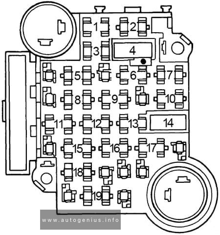
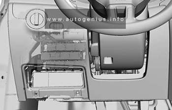
Engine compartment
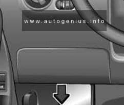
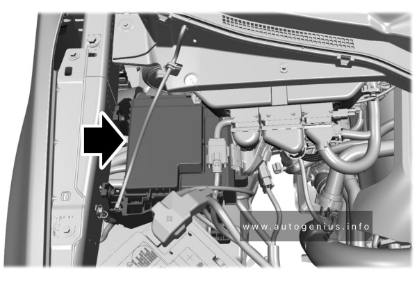
Fuse box location
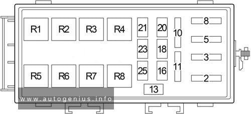
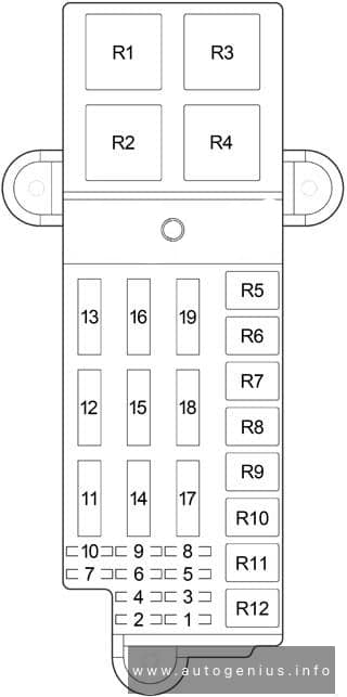
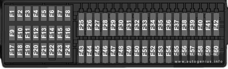
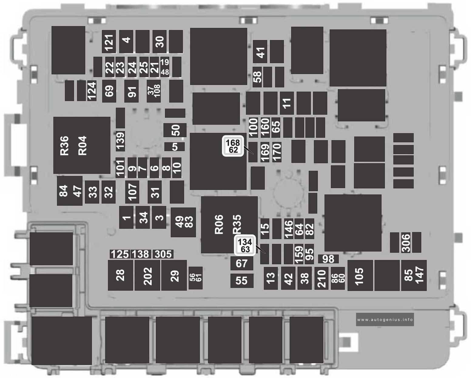
Fuse box diagram
Version 1
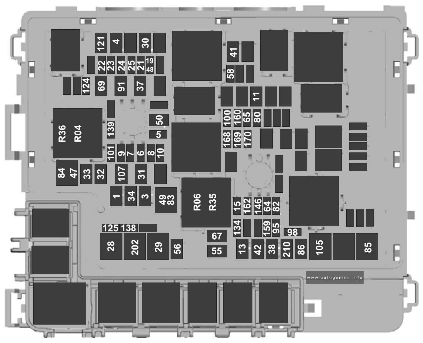
Assignment of the fuses in the engine compartment (version 1)
| Fuse location | Fuse rating | Protected component |
| 1 | 40A | Body control module – battery power in feed 1 |
| 3 | 40A | Body control module – battery power in feed 2 |
| 4 | 30A | Fuel pump |
| 5 | 5A | Keep-alive power Powertrain control module (hybrid) |
| 6 | 25A | Powertrain control module power |
| 7 | 20A | Powertrain control module power |
| 8 | 20A | Powertrain control module power (hybrid) |
| 10A | Powertrain control module power (gas, diesel) | |
| 9 | 20A | Powertrain control module power |
| 10 | 20A | Powertrain control module power (diesel) |
| 11 | 30A | Starter motor |
| 13 | 40A | Blower motor |
| 15 | 25A | Horn |
| 19 | 20A | Snow plow switch Rear heated seats (gas) |
| 21 | 10A | Headlamp run/start feed |
| 22 | 10A | Electronic power assist steering |
| 23 | 10A | Electric brake boost |
| 24 | 10A | Powertrain control module (gas, hybrid), Transmission control module (diesel), Glow plug control module (diesel) |
| 25 | 10A | Center high-mounted stop lamp camera, Trailer camera, 2 kW inverter, 24 V alternator – run/start feed, Analog rear video camera |
| 28 | 50A | Electric brake boost |
| 29 | 50A | Electric brake boost |
| 30 | 40A | Driver power seat |
| 31 | 30A | Passenger power seat |
| 32 | 20A | Auxiliary power point |
| 33 | 20A | Auxiliary power point, USB smart charger |
| 34 | 20A | Auxiliary power point |
| 37 | 30A | Tailgate module |
| 38 | 40A | Climate controlled seat module, Power running boards |
| 41 | 25A | Power sliding back window |
| 42 | 30A | Trailer brake control module |
| 47 | 50A | Cooling fan |
| 48 | 20A | Rear heated seats (diesel, hybrid) |
| 49 | 50A | Cooling fan |
| 50 | 40A | Heated backlight (gas, hybrid) |
| 55 | 30A | Trailer tow park lamps |
| 56 | 20A | Trailer tow stop and turn lamps |
| 58 | 10A | Trailer tow backup lamps |
| 64 | 25A | Four-wheel drive |
| 65 | 15A | Transmission control module (diesel) |
| 67 | 20A | Transmission run/start |
| 69 | 30A | Left-hand windshield wiper |
| 80 | 15A | Not used (spare) |
| 82 | 25A | Four-wheel drive |
| 83 | 50A | Supplemental heater (diesel) |
| 84 | 50A | Supplemental heater (diesel) |
| 85 | 50A | Supplemental heater (diesel) |
| 86 | 25A | Selective catalytic reduction system |
| 91 | 20A | Trailer tow light module |
| 95 | 15A | Powertrain control module power (hybrid) |
| 98 | 10A | Powertrain control module power (hybrid), Coolant pumps (hybrid) |
| 100 | 15A | Left-hand headlamps |
| 101 | 15A | Right-hand headlamps |
| 105 | 50A | Active front steering |
| 107 | 30A | Trailer tow battery charge |
| 121 | 30A | Fuel filter heater (diesel) |
| 124 | 5A | Rain sensor module |
| 125 | 10A | USB smart charger |
| 134 | 25A | Multi-contour seats relay |
| 138 | 10A | Tailgate release |
| 139 | 5A | USB smart charger |
| 146 | 15A | Traction battery control module |
| 159 | 5A | DC/DC power (hybrid) |
| 160 | 10A | Smart data link control |
| 162 | 7.5A | Not used (spare) |
| 168 | 20A | Traction battery control module (hybrid) |
| 169 | 10A | Motor electric cool pump (hybrid) |
| 170 | 10A | Pedestrian alert control module (hybrid), Traction battery control module (hybrid), Electric motor cool pump (hybrid) |
| 202 | 60A | Body control module B+ |
| 210 | 30A | Body control module start stop |
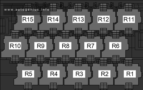
| Relay number | Protected component |
| R04 | Electronic fan relay 1 |
| R06 | Electronic fan relay 3 |
| R35 | Supplemental heater |
| R36 | Supplemental heater |
Fuse box diagram
Version 2
Assignment of the fuses in the engine compartment (version 2)
| Item | Rating | Protected component |
| 1 | 40A | Body control module – battery power in feed 1 |
| 3 | 40A | Body control module – battery power in feed 2 |
| 4 | 30A | Fuel pump |
| 5 | 5A | Powertrain control module coil |
| 6 | 25A | Powertrain control module power |
| 7 | 20A | Powertrain control module power |
| 8 | 20A | Powertrain control module power (hybrid) |
| 10A | Powertrain control module power (gas, diesel, Raptor, Tremor) | |
| 9 | 20A | Powertrain control module power |
| 10 | 20A | Powertrain control module power (diesel) |
| 11 | 30A | Starter motor |
| 13 | 40A | Blower motor |
| 15 | 25A | Horn |
| 19 | 20A | Snow plow switch (gas), Rear heated seats (gas, diesel, hybrid) |
| 21 | 10A | Headlamp run/start feed |
| 22 | 10A | Electronic power assist steering |
| 23 | 10A | Electric brake boost |
| 24 | 10A | Powertrain control module (gas, hybrid), Transmission control module (diesel), Glow plug control module (diesel) |
| 25 | 10A | Center high-mounted stop lamp camera, Trailer camera,2 kW inverter, 24 V alternator – run/start feed, Analog rear video camera |
| 28 | 50A | Electric brake boost |
| 29 | 50A | Electric brake boost |
| 30 | 40A | Driver power seat |
| 31 | 30A | Passenger power seat |
| 32 | 20A | Auxiliary power point |
| 33 | 20A | Auxiliary power point, USB smart charger |
| 34 | 20A | Auxiliary power point |
| 37 | 30A | Tailgate module |
| 38 | 40A | Climate controlled seat module, Power running boards |
| 41 | 25A | Power sliding back window |
| 42 | 30A | Trailer brake control module |
| 47 | 50A | Cooling fan (gas, hybrid, Raptor, Tremor) |
| 48 | 20A | Rear heated seats (Raptor, Tremor) |
| 49 | 50A | Cooling fan (gas, hybrid, Raptor, Tremor) |
| 50 | 40A | Heated backlight (gas, hybrid) |
| 55 | 30A | Trailer tow park lamps |
| 56 | 20A | Trailer tow stop and turn lamps (4-pin connector) |
| 58 | 10A | Trailer tow backup lamps |
| 60 | 15A | Upfitter 1 relay (Raptor, Tremor) |
| 61 | 15A | Upfitter 2 relay (Raptor, Tremor) |
| 62 | 10A | Upfitter 3 relay (Raptor, Tremor) |
| 63 | 10A | Upfitter 4 relay (Raptor, Tremor) |
| 64 | 25A | Four-wheel drive |
| 65 | 15A | Transmission control module (diesel) |
| 67 | 20A | Transmission run/start |
| 69 | 30A | Left-hand windshield wiper |
| 82 | 25A | Four-wheel drive |
| 83 | 50A | Supplemental heater (diesel) |
| 84 | 50A | Supplemental heater (diesel) |
| 85 | 50A | Supplemental heater (diesel) |
| 86 | 25A | Selective catalytic reduction system (diesel) |
| 91 | 20A | Trailer tow light module |
| 95 | 15A | Powertrain control module power (hybrid) |
| 98 | 10A | Powertrain control module power (hybrid) Coolant pumps (hybrid) |
| 100 | 15A | Left-hand headlamps |
| 101 | 15A | Right-hand headlamps |
| 105 | 50A | Active front steering |
| 107 | 30A | Trailer tow battery charge |
| 108 | 15A | Spot lamps (police) |
| 121 | 30A | Fuel filter heater (diesel) |
| 124 | 5A | Rain sensor module |
| 125 | 10A | USB smart charger |
| 134 | 25A | Multi-contour seats relay (gas, diesel, hybrid) |
| 138 | 10A | Tailgate release |
| 139 | 5A | USB smart charger |
| 146 | 15A | Traction battery control module (hybrid) |
| 147 | 40A | Change air cooler fan relay (Raptor, Tremor) |
| 159 | 5A | DC/DC power (hybrid) |
| 160 | 10A | Smart data link control |
| 168 | 15A | Traction battery control module (hybrid) |
| 169 | 10A | Motor electric cool pump (hybrid) |
| 170 | 10A | Pedestrian alert control module (hybrid), Traction battery control module (hybrid), Electric motor cool pump (hybrid) |
| 202 | 60A | Body control module B+ |
| 210 | 30A | Body control module start stop |
| 305 | 5A | Upfitter 5 relay (Raptor, Tremor) |
| 306 | 5A | Upfitter 6 relay (Raptor, Tremor) |
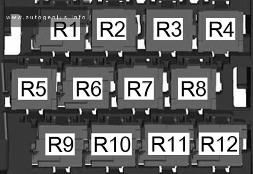
| Relay number | Protected component |
| R04 | Electronic fan relay 1 |
| R06 | Electronic fan relay 3 |
| R35 | Supplemental heater |
| R36 | Supplemental heater |
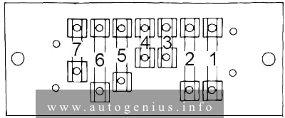
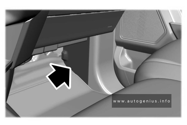
Body Control Module Fuse Box
Fuse box location
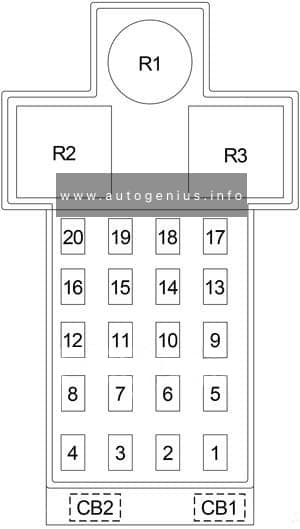
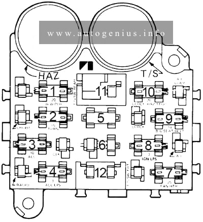
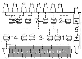
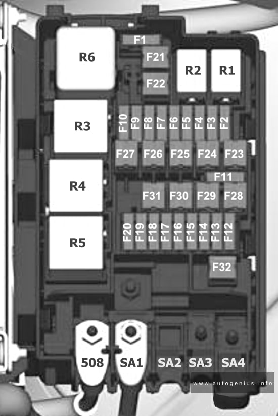
Fuse box diagram
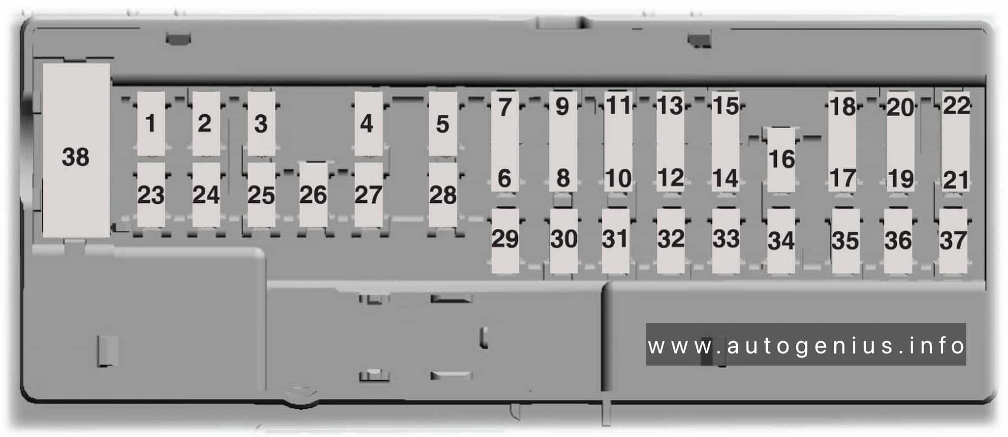
Assignment of the fuses in the body control module
| Fuse location | Fuse rating | Protected component |
| 1 | – | Not used |
| 2 | 10A | Delayed accessory feed |
| 3 | 7.5A | Wireless charger |
| 4 | 20A | Not used |
| 5 | – | Not used |
| 6 | 10A | Driver power window switch |
| 7 | 10A | Gear shift module |
| 8 | 5A | Cell phone passport module |
| 9 | 5A | Combined sensor module |
| 10 | – | Not used |
| 11 | – | Not used |
| 12 | 7.5A | Enhanced central gateway, Climate control |
| 13 | 7.5A | Instrument cluster, Steering column control module |
| 14 | 15A | Not used (spare) |
| 15 | 15A | Integrated control panel, SYNC |
| 16 | – | Not used |
| 17 | 7.5A | Headlamp control module |
| 18 | 7.5A | Not used |
| 19 | 5A | Headlamp switch |
| 20 | 5A | Passive start, Ignition switch, Key inhibit solenoid |
| 21 | 5A | Trailer brake switch |
| 22 | 5A | Not used |
| 23 | 30A | Driver door control module |
| 24 | 30A | Moonroof |
| 25 | 20A | Not used |
| 26 | 30A | Passenger door control module |
| 27 | 30A | Not used |
| 28 | 30A | Amplifier |
| 29 | 15A | 12 inch display Adjustable pedals |
| 30 | 5A | Not used |
| 31 | 10A | RF receiver, Driver monitor, Terrain management switch |
| 32 | 20A | Audio control module |
| 33 | – | Not used |
| 34 | 30A | Run/start relay |
| 35 | 5A | 400 watt inverter run/start |
| 36 | 15A | Auto-dimming interior mirror, Rear heat seat run/start, Adaptive front steering run/start, Heated wheel (vehicles without adaptive front steering) |
| 37 | 20A | Advanced driver-assistance systems |
| 38 | 30A circuit breaker | Rear power windows |
WARNING: Terminal and harness assignments for individual connectors will vary depending on vehicle equipment level, model, and market.