KIA Sportage (QL; 2017 – 2023) – fuse box diagram
Year of production: 2017, 2018, 2019, 2020, 2021, 2022
The 4th generation Kia Sportage was produced in 2016, 2017, 2018, 2019, 2020, 2021, 2022, 2023 with both gasoline and diesel engines. In this publication you will find a designation of the 4th generation Kia Sportage fuses and relays with boxes diagrams and their locations. Let’s highlight the fuse responsible for the cigarette lighter.
Instrument panel (driver’s side fuse panel)
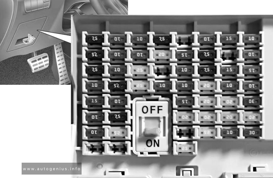
Fuse box location
Located under the dashboard on the driver’s side behind the protective cover.
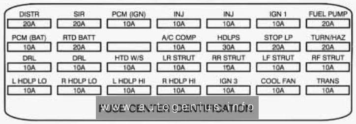
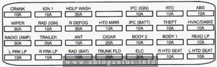
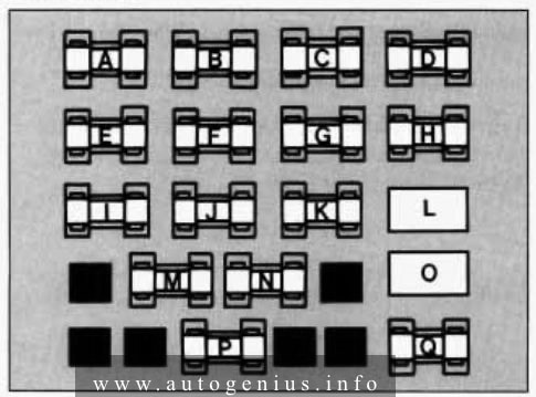
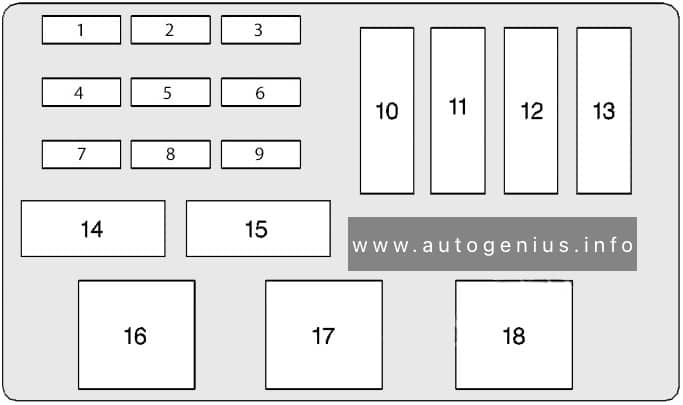
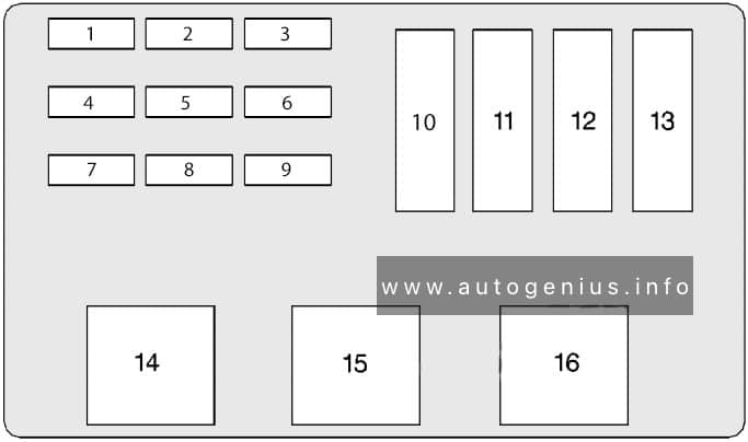
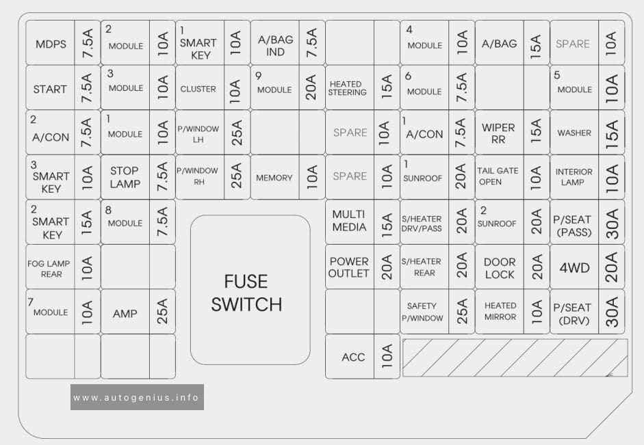
Fuse box diagram
Version 1
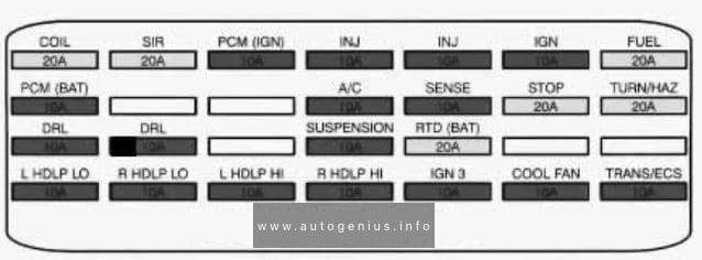
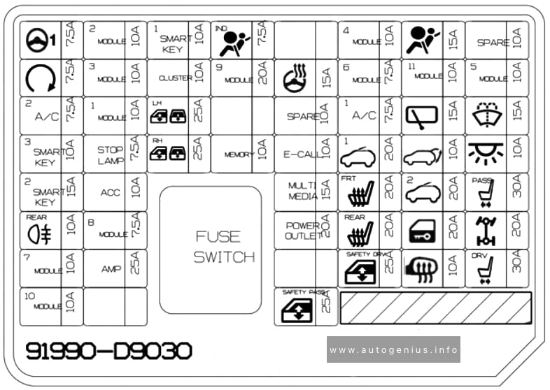
Version 2
| Fuse name | Ampere rating [A] | Protected component |
| MDPS | 7,5 | MDPS Unit |
| MODULE 2 | 10 | Headlamp LH/RH |
| SMART KEY 1 | 10 | Smart Key Control Module/Immobilizer Module |
| A/BAG IND | 7,5 | Instrument Cluster [Audio & Manual A/C] Hazard Switch [Audio & Auto A/C] A/C Control Module [Navigation] Center Facia Lamp |
| MODULE 4 | 10 | Console Switch, Blind Spot Detection Radar LH/RH, AWD ECM, Crash Pad Switch, BCM, Lane Departure Warning Control Module |
| A/BAG | 15 | SRS Control Module |
| START | 7,5 | [W/O Smart Key & IMMO.] ICM Relay Box (Burglar Alarm Relay), Ignition Switch [With Smart Key / IMMO.] Transaxle Range Switch, ECM, Smart Key Control Module |
| MODULE 3 | 10 | Front/Rear Seat Warmer Control Module, ATM Shift Lever ILL., Front Air Ventilation Seat Control Module, A/V & Navigation Head Unit, Electro Chromic Mirror, Audio, A/C Control Module, Multipurpose Check Connector, Adaptive Front Lighting Module |
| CLUSTER | 10 | Instrument Cluster |
| MODULE 9 | 20 | PCB Block (Fuse – ABS 3, VACUUM PUMP 2, ECU 6, AEB, TCU 2, MODULE) |
| HEATED STEERING |
15 | BCM |
| MODULE 6 | 7,5 | Front/Rear Seat Warmer Control Module, Front Air Ventilation Seat Control Module |
| MODULE 5 | 10 | BCM, Smart Key Control Module |
| A/CON 2 | 7,5 | A/C Control Module |
| MODULE 1 | 10 | BCM, ATM Shift Lever |
| P/ WINDOW LH | 25 | Power Window Main Switch |
| A/CON 1 | 7,5 | A/C Control Module, Cluster Ionizer, E/R Junction Block (Blower Relay) |
| WIPER RR | 15 | Rear Wiper Motor, ICM Relay Box (Rear Wiper Relay) |
| WASHER | 15 | Multifunction Switch |
| SMART KEY 3 | 10 | [W/O Smart Key] Immobilizer Module [With Smart Key] Smart Key Control Module, Start/Stop Button Switch |
| STOP LAMP | 7,5 | Smart Key Control Module, Stop Lamp Switch |
| P/ WINDOW RH | 25 | Power Window Main Switch, Passenger Power Window Switch |
| MEMORY | 10 | Wireless Charger, Instrument Cluster, Data Link Connector, BCM, ICM Relay Box (Outside Mirror Folding/Unfolding Relay), Electro Chromic Mirror, A/C Control Module, Console Switch |
| SUN ROOF 1 | 20 | Panorama Sunroof |
| TAIL GATE OPEN |
10 | Tail Gate Relay |
| INTERIOR LAMP | 10 | Ignition Key Ill.& Door Warning Switch, Room Lamp, Overhead Console Lamp, Front Vanity Lamp LH/RH, Rear Personal Lamp LH/RH, Luggage Lamp, Glove Box Lamp |
| SMART KEY 2 | 15 | Smart Key Control Module |
| MODULE 8 | 7,5 | Key Solenoid |
| MULTI MEDIA | 15 | Audio, A/V & Navigation Head Unit, Rear USB Charger |
| S/HEATER DRV/PASS |
20 | Front Seat Warmer Control Module, Front Air Ventilation Seat Control Module |
| SUN ROOF 2 | 20 | Panorama Sunroof |
| P/SEAT (PASS) | 30 | Passenger Seat Manual Switch |
| POWER OUTLET | 20 | Front Power Outlet #1 (Front Cigarette Lighter) |
| S/HEATER REAR |
20 | Rear Seat Warmer Control Module |
| DOOR LOCK | 20 | Door Lock/Unlock Relay |
| 4WD | 20 | AWD ECM |
| MODULE 7 | 10 | Hazard Switch, Driver/Passenger Smart Key Outside Handle, AEB Sensor |
| AMP | 25 | AMP |
| SAFETY P/ WINDOW |
25 | Driver Safety Power Window Module |
| HEATED MIRROR |
10 | Driver/Passenger Power Outside Mirror, A/C Control Module |
| P/SEAT (DRV) | 30 | Driver Seat Manual Switch |
| ACC | 10 | Rear USB Charger, AMP, Power Outside Mirror Switch, PCB Block(Power Outlet Relay), Smart Key Control Module, Audio, A/V & Navigation Head Unit, BCM, Wireless Charger |
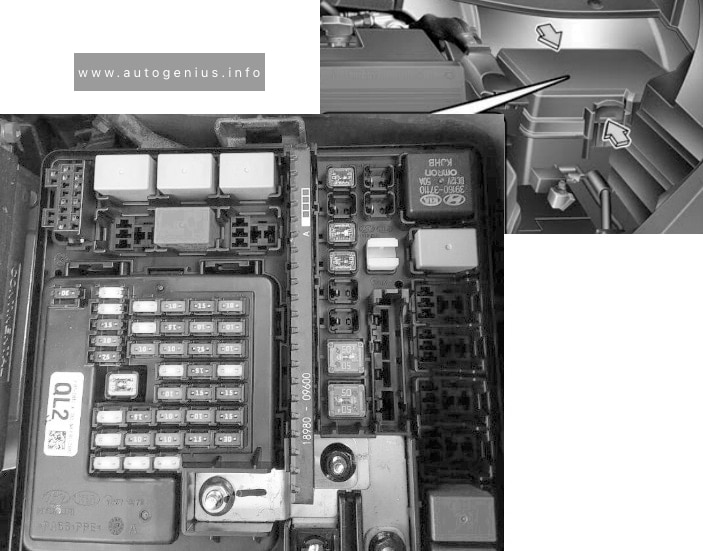
Engine compartment fuse panel
Fuse box location
Located on the left side of the engine compartment.
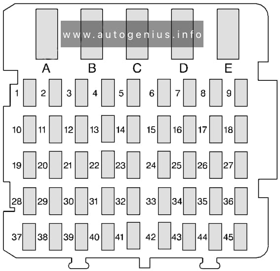
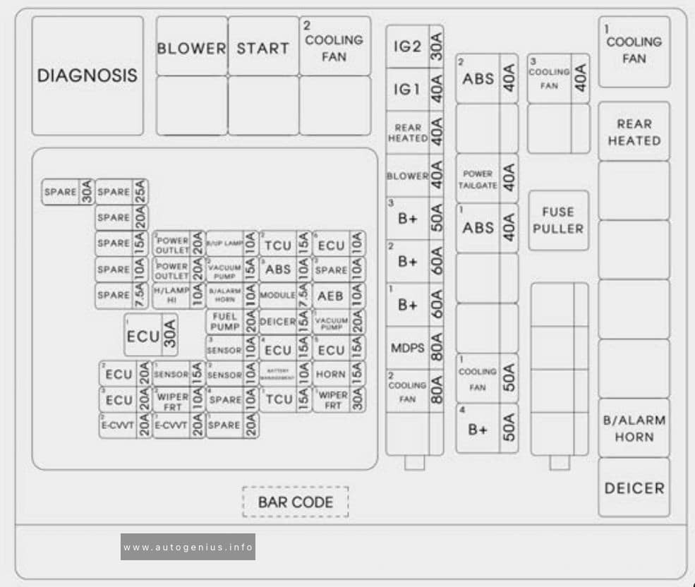
Fuse box diagram
Version 1
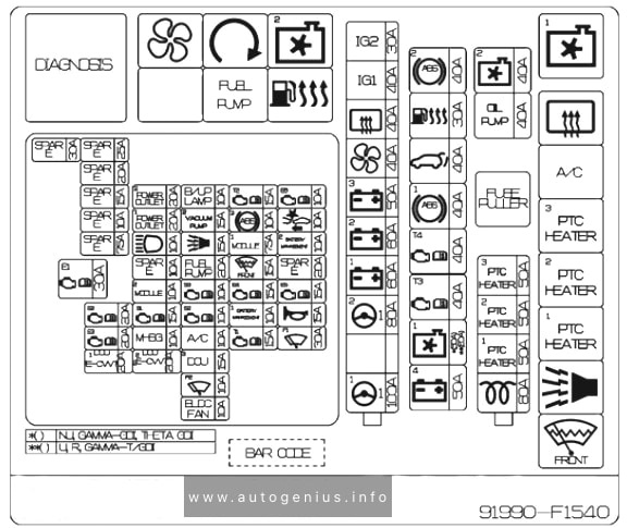
Version 2
| Fuse name | Ampere rating [A] | Protected component | |
| MULTI FUSE | COOLING FAN 2 | 80 | Cooling Fan Motor |
| MDPS | 80 | MDPS Unit | |
| B+ 1 | 60 | Smart Junction Block (IPS 2 (5CH), IPS 3 (2CH), IPS 4 (2CH), IPS 5 (2CH), IPS 6 (1CH), Fuse – AMP) | |
| B+ 2 | 60 | Smart Junction Block (IPS 1 (5CH), Fuse – MODULE 7, SMART KEY 2, SMART KET 3, MODULE 8, STOP LAMP) | |
| B+ 3 | 50 | Smart Junction Block (Fuse – SUNROOF 1, SUNROOF 2, S/HEATER DRV/PASS, S/HEATER REAR, SAFETY P/WINDOW, Power Window Relay | |
| BLOWER | 40 | Blower Relay | |
| REAR HEATED | 40 | Rear Heated Relay | |
| IG1 | 40 | [W/O Smart Key] Ignition Switch, [With Smart Key] PCB Block (PDM (IG1)/PDM (ACC) Relay) | |
| IG2 | 30 | Start Relay, [W/O Smart Key] Ignition Switch, [With Smart Key] PCB Block (PDM (IG2) Relay) | |
| FUSE | B+ 4 | 50 | Smart Junction Block (Fuse – AWD, P/SEAT (DRV), P/SEAT (PASS), TAIL GATE OPEN, DOOR LOCK, Leak Current Autocut Device Relay) |
| COOLING FAN 1 | 50 | Cooling Fan 1 Relay | |
| ABS 1 | 40 | ESC Control Module, Multipurpose Check Connector | |
| POWER TAIL GATE |
40 | Power Tail Gate Module | |
| ABS 2 | 40 | ESC Module | |
| COOLING FAN 3 | 40 | Cooling Fan 1 Relay | |
| E-CVVT 1 | 20 | PCM | |
| E-CVVT 2 | 20 | PCM | |
| WIPER FRT 1 | 30 | [W/O Smart Key] Ignition Switch, [With Smart Key] PDM (IG2) Relay | |
| TCU 1 | 15 | PCM | |
| WIPER FRT 2 | 10 | BCM, PCM | |
| ECU 3 | 20 | PCM | |
| HORN | 15 | A Horn Relay | |
| BATTERY MANAGEMENT |
10 | Battery Sensor | |
| SENSOR 2 | 10 | Fuel Pump Relay, Oil Control Valve, Purge Control Solenoid Valve, Variable Intake Solenoid Valve, RCV Control Solenoid Valve | |
| SENSOR 1 | 15 | Oxygen Sensor (Up/Down) | |
| ECU 2 | 20 | Ignition Coil #1/#2/#3/#4 | |
| ECU 4 | 15 | PCM | |
| SENSOR 3 | 10 | E/R Junction Block (Cooling Fan 1 Relay), Canister Close Valve | |
| FUEL PUMP | 20 | Fuel Pump Relay | |
| AEB | 10 | AEB Sensor | |
| MODULE | 7,5 | Stop Lamp Switch | |
| B/ALARM HORN |
10 | E/R Junction Block (B/Alarm Horn Relay) | |
| H/LAMP HI | 10 | BI-Function H/LP Relay | |
| ABS 3 | 10 | ESC Module | |
| POWER OUTLET 1 |
20 | Front Power Outlet #2 | |
| ECU 6 | 10 | PCM | |
| TCU 2 | 15 | Transaxle Range Switch | |
| B/UP LAMP | 10 | Rear Bumper Lamp LH/RH, Electro Chromic Mirror | |
| POWER OUTLET 2 |
20 | Rear Power Outlet | |
| ECU 1 | 30 | Engine Control Relay | |
| DEICER | 15 | E/R Junction Block (Deicer Relay) | |
| VACUUM PUMP 1 |
20 | Vacuum Pump | |
| VACUUM PUMP 2 |
15 | Vacuum Pump, Cooling Fan Motor, Vacuum Switch | |
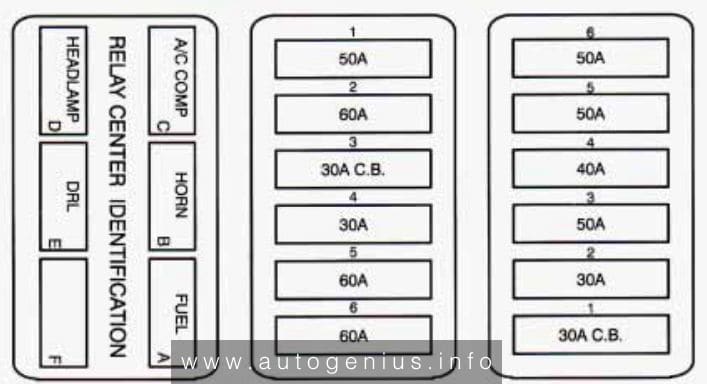
Relay
| Relay name | Type |
| Cooling Fan 1 Relay | MINI |
| Rear Defogger Relay | MICRO |
| B/A Horn Relay | MICRO |
| Deicer Relay | MICRO |
| Cooling Fan 2 Relay | MICRO |
| Start Relay | MICRO |
| Blower Relay | MICRO |
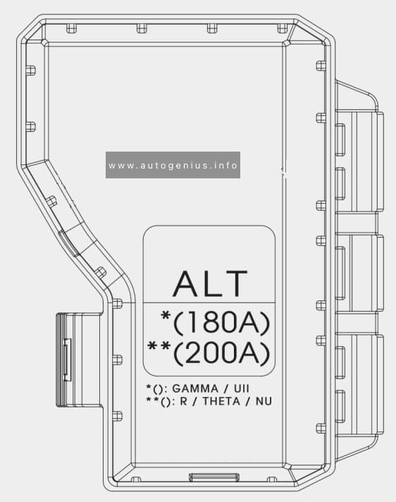
Engine compartment fuse panel (Battery terminal cover)
On the positive terminal of the storage battery there is a high-power main power fuse made in the form of a fusible link.
WARNING: Terminal and harness assignments for individual connectors will vary depending on vehicle equipment level, model, and market.