Jeep Gladiator (JT; 2019 – 2023) – fuse and relay box diagram
Year of production: 2019, 2020, 2021, 2022, 2023
The midsize pickup truck Jeep Gladiator (JT) is available from 2029 to 2023. In this article, you will find fuse box diagrams of Jeep Gladiator 2020, 2020, 2022, and 2023, get information about the location of the fuse panels inside the car, and learn about the assignment of each fuse (fuse layout).
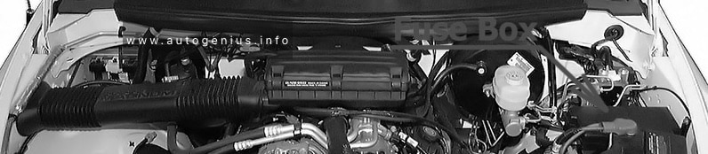
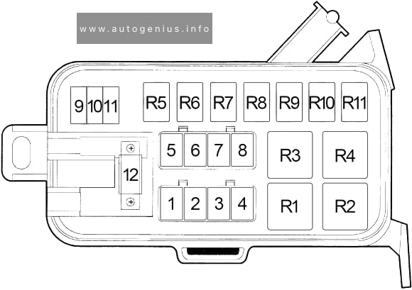
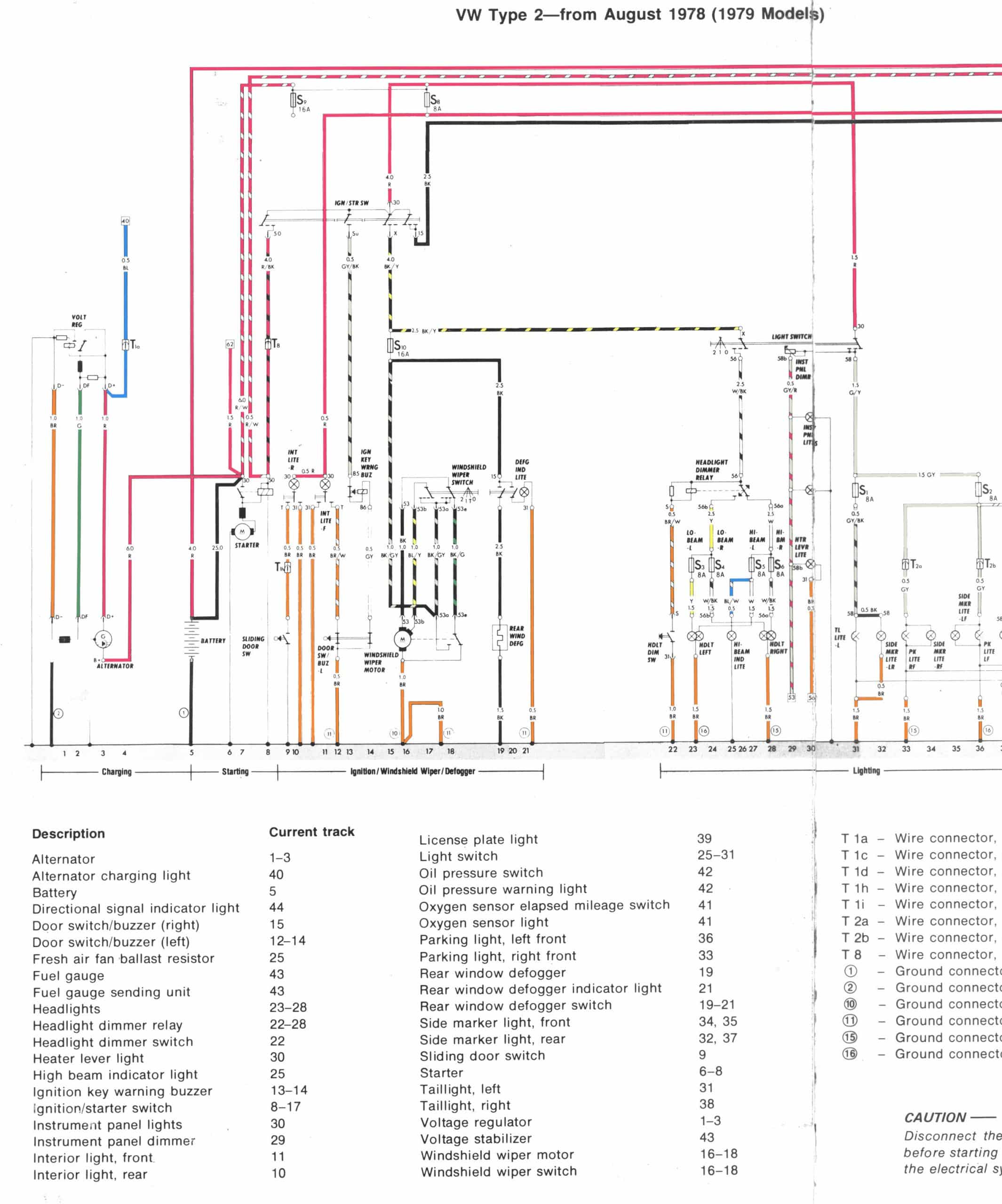
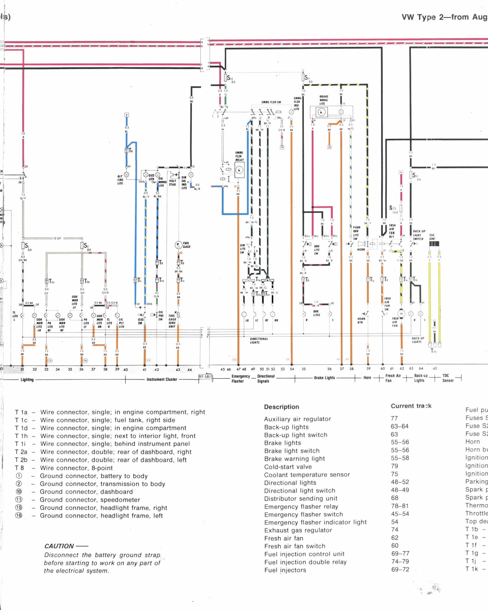
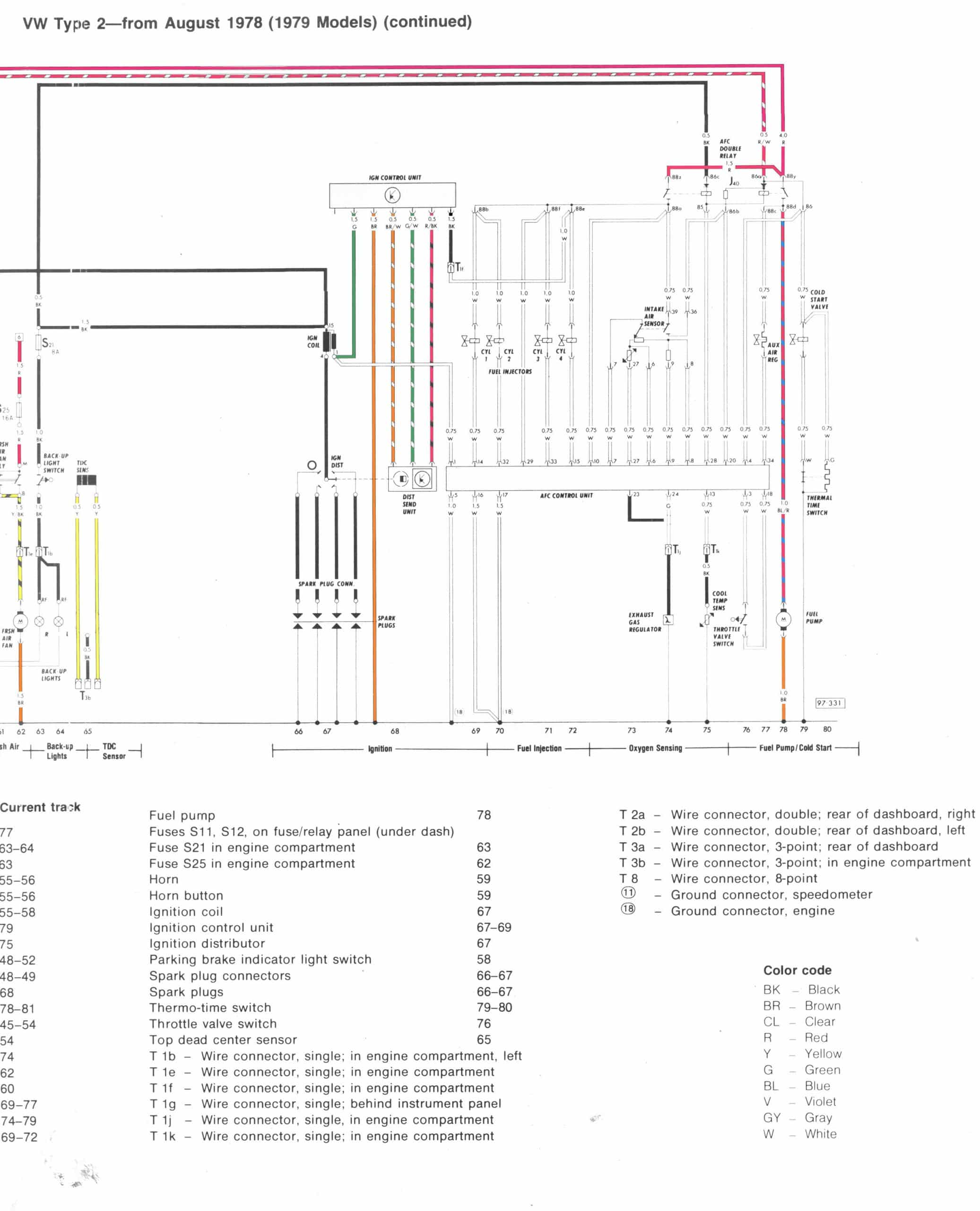
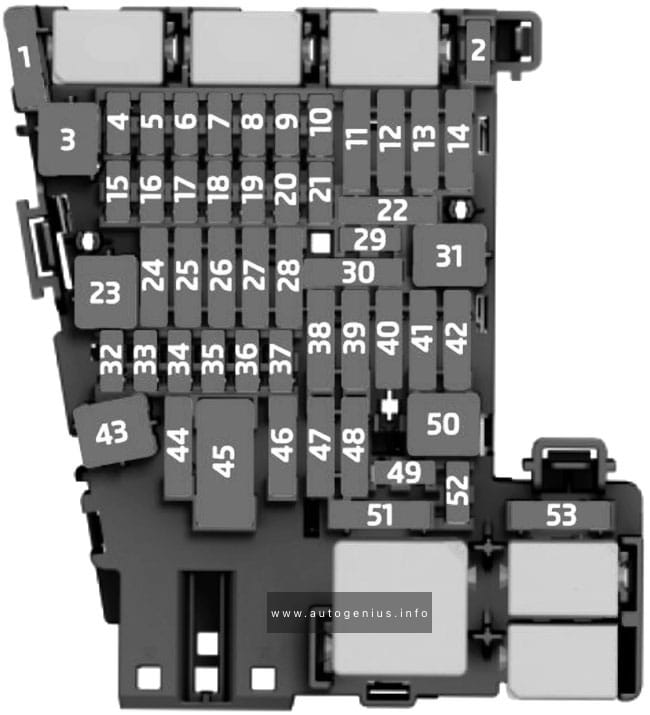
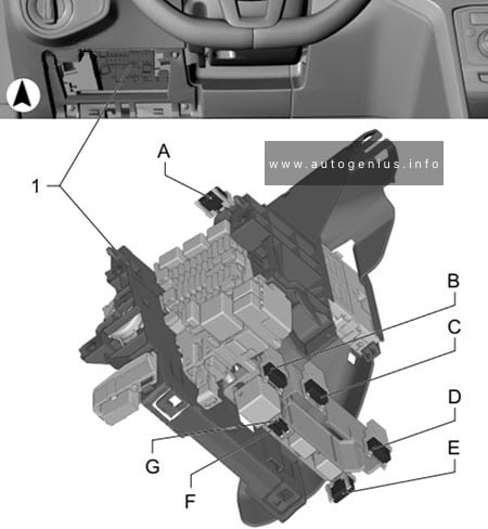
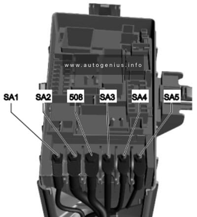
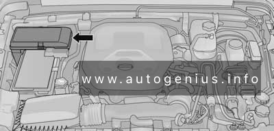
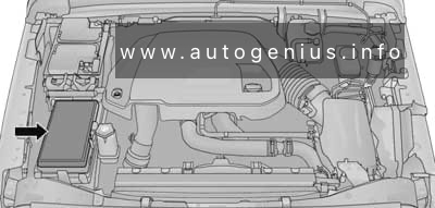
Engine Compartment Fuse Box
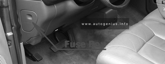
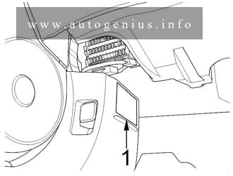
Fuse Box Location
The Power Distribution Center is located in the engine compartment near the battery.
Gasoline:
Diesel:
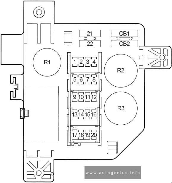
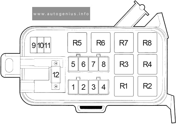
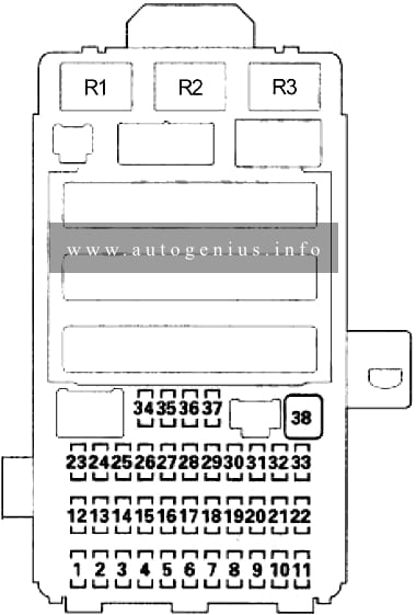
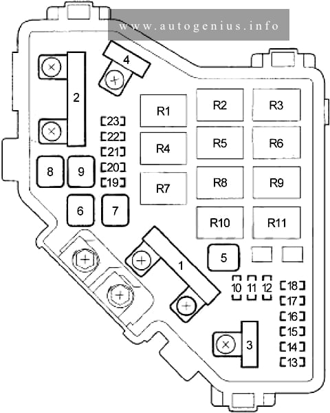
Fuse Box Diagram
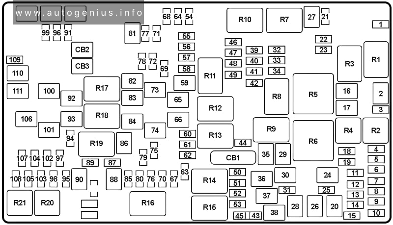
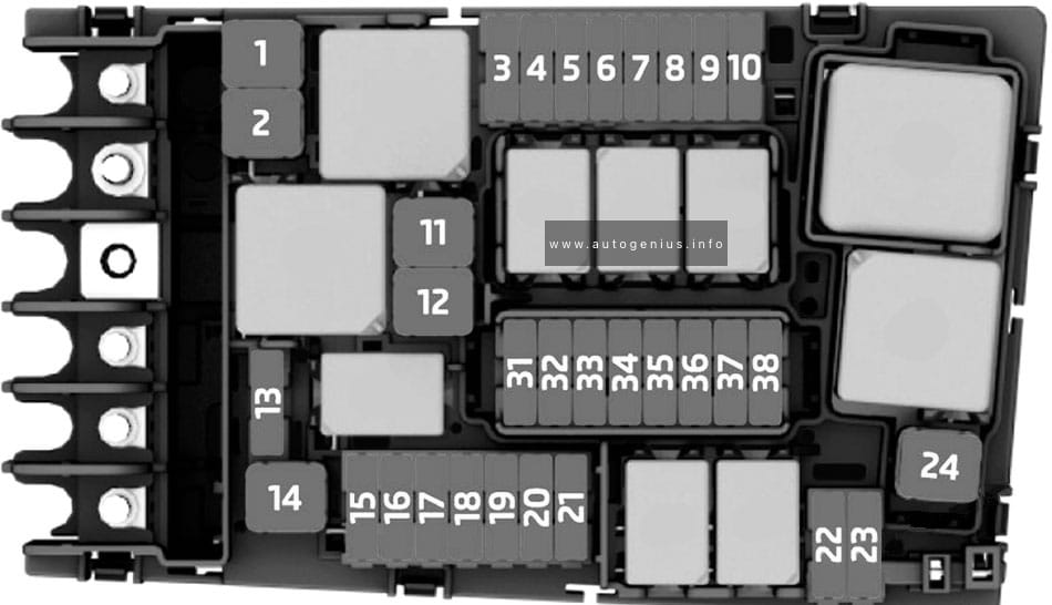
Assignment of the fuses in the Power Distribution Center (2019-2023)
| No. |
A |
Circuit Protected |
| 1 | 5 | PHEV: HV Electric Coolant Heater Enable |
| 2 | 40 | except PHEV: Starter |
| 3 | 5 | Intelligent Battery Sensor (IBS) |
| 4 | 20 | Fuel Pump Motor, Fuel Pump Control Module (FPCM) |
| 25 | 6.4L Hemi V8 (’18-’23): Fuel Pump | |
| 5 | 5 | Security Gateway |
| 6 | 15 | PHEV: Battery Pack Control Module (BPCM) |
| 7 | 15 | Wrangler: Low Temp Radiator Cooling Pump (LTR) |
| 15 | PHEV: PECP-2 |
|
| 8 | 15 | ZF 8HP75: Transmission Control Module (TCM) |
| 9 | 5 | PHEV: Integrated Dual Charging Module (IDCM) |
| 10 | 15 | Key Ignition Node (KIN), Radio Frequency Hub (RF HUB), Electric Steering Column Lock (ESCL) |
| 11 | 10 | UCI Port (USB & AUX) |
| 12 | 25 | HiFi Amplifier |
| 13 | 10 | PHEV: Power Inverter Module (PIM) – Redundant Main Power Supply |
| 14 | 10 | PHEV: Power Inverter Module (PIM) – Main Power Supply |
| 15 | 15 | Instrument Panel Cluster (IPC), Switch Bank-Heavy Duty Electrical Pkg |
| 16 | – | – |
| 17 | 40 | PHEV: Transmission Oil Pump |
| 18 | 10 | Air Conditioning Clutch |
| 19 | 5 | PHEV: Charge Port Indicator |
| 20 | 30 | Interior Lights – Central Body Controller (CBC) |
| 21 | 20 | Wrangler: Rear Wiper |
| 22 | 10 | Engine Control Module (ECM)/Powertrain Control Module (PCM), Motor Generator Unit (MGU – Wrangler), Power Pack Unit (PPU – Wrangler), Power Inverter Module (PIM – PHEV) |
| 23 | 10 | except PHEV: Engine Control Module (ECM)/Powertrain Control Module (PCM) |
| 24 | 30 | ’23-: Passenger’s Power Seat |
| 25 | 10 | Module Shift By Wire |
| 26 | 40 | Exterior Lights No.1 – Central Body Controller (CBC) |
| 27 | 30 | Front Wipers |
| 28 | 40 | Power Locks – Central Body Controller (CBC) |
| 29 | 40 | Exterior Lights No.2 – Central Body Controller (CBC) |
| 30 | 30 | ’23-: Power Step/Slider |
| 31 | 10 | Data Link Connector (DLC) |
| 32 | 10 | Occupant Classification Module (OCM), Driver Presence Detection Module (DPDM), Heating Ventilation Air Conditioning (HVAC) Module, Steering Column Lock (SCL) |
| 33 | 10 | ParkTronics System (PTS), Airbag Disable Lamps, Infrared Camera Module (IRCM) |
| 34 | 10 | Electronic Stability Control (ESC), Electric Hydraulic Power Steering (EHPS), Smart Bar Control Module (SBCM) |
| 35 | 30 | except PHEV: Brake Vacuum Pump |
| 36 | 30 | Electric Brake Module (Trailer Tow) |
| 37 | 30 | Trailer Tow Connector (7W) |
| 38 | 20 | Engine Control Module (ECM) |
| 39 | 15 | 3.6L (Wrangler MHEV): Mild Hybrid Motor Generator Unit (MGU) Coolant Pump |
| 40 | 15 | DriveTrain Control Module (DTCM), Axle Lock (FT/RR) |
| 41 | 15 | Instrument Cluster (IC), Security GateWay (SGW) |
| 42 | 10 | with Stop/Start: Power Control Relay Control Feed (except PHEV) |
| 43 | 20 | Wrangler: Power Outlet – Batt (Cargo) (You can select to switch the Cargo Power Outlet from F43 battery fed power to this position F45 which is fed when the ignition in ON) |
| 44 | 10 | InfraRed Camera (IRCAM) – Heaters |
| 45 | 20 | Wrangler: Power Outlet – Ignition (Cargo) |
| 46 | 10 | Headlamp Switch, Auto Headlamp Leveling Module, Headlamp Leveling Motors |
| 47 | 10 | PHEV: Quiet Vehicle Pedestrian Module (QVPM) |
| 48 | – | – |
| 49 | 10 | Occupant Restraint Controller (ORC) |
| 50 | 10 | Heavy Duty (HD) Aссessory |
| 51 | 10 | Wrangler: Digital TV (DSRC), USB, InSide RearView Mirror (ISRVM), Compass Module (CSGM), Inverter 400W (PHEV), Engine Control Module (ECM – PHEV), Power Inverter Module (PIM – PHEV) |
| 10 | Gladiator: Humidity Light Rain Sensor (HLRS), Inverter 400W, USB, InSide RearView Mirror (ISRVM), Compass Module (CSGM), Digital TV (DTV) | |
| 52 | 20 | Cigarette Lighter |
| 53 | 10 | Gladiator, PHEV: Wireless Speaker |
| 54 | – | – |
| 55 | 10 | Wrangler (’22-): Central Vision Processing Module (CVPM) |
| 10 | Gladiator: Central Vision Processing Module (CVPM) or Parktronics Module | |
| 56 | 10 | In Car Temperature Sensor, PTC Heater Coil (’20- (except PHEV)) |
| 57 | 20 | Front Driver Heated Seat |
| 58 | 20 | Front Passenger Heated Seat |
| 59 | 30 | ’23-: Driver Power Seat |
| 60 | 15 | Heated Steering – Comfort Steering Wheel Module (CSWM) |
| 61 | 10 | Left Blind Spot Sensor (LBSS), Right Blind Spot Sensor (RBSS), Central ADAS Decision Module (CADM Lo (’23-)) |
| 62 | 10 | ’22-: Exhaust Solenoid (except PHEV) |
| 63 | 10 | Occupant Restraint Controller (ORC) |
| 64 | – | – |
| 65 | 50 | Gladiator, PHEV: Power Inverter 400W |
| 66 | 40 | Front Blower Motor (HVAC) |
| 67 | 15 | PHEV: BCP – Lo Temp Active Pump |
| 68 | – | – |
| 69 | 5 | Wrangler (’18-’23): Motor Generator Unit (MGU), Belt Starter Generator (BSG) |
| 10 | ’23-: KIN / RF Hub | |
| 70 | 25 | Gasoline: Injectors, Ignition Coils |
| 25 | Diesel: Glow Plug Module | |
| 71 | 10 | PHEV: Battery Coolant Heater |
| 72 | 10 | HD ELEC ACC PKG |
| 73 | 20 | Wrangler: Power Top (LT) |
| 74 | 20 | Wrangler: Power Top (RT) |
| 75 | 10 | Wrangler (’18-’23): Belt Starter Generator (BSG), Power Pack Unit – Battery Pack Control Module & Auxiliary Power Module (PPUBPCM & APM) |
| 5 | PHEV: Battery Charge Indicator, Switch Bank PHEV Mode | |
| 76 | 20 | Gasoline: Engine Control Module (ECM) |
| 20 | Diesel: Powertrain Control Module (PCM) | |
| 77 | 10 | Heated Mirrors |
| 78 | 10 | Wrangler: Computer, Intrusion Module, Siren, Intrusion Sensor |
| 79 | 20 | Smart Bar Control Module |
| 80 | 15 | Powertrain Control Module (PCM), Block Shift Solenoid No.1 & No.2 (Wrangler – ’22-), ELCM Module (PHEV), Fuel Tank Isolation Solenoid (PHEV) |
| 10 | Wrangler (’22-’23): Vapor Blocking Valve (BSG) | |
| 81 | 30 | Rear Window Defogger (EBL) |
| 82 | 30 | Diesel: Fuel Heater |
| 83 | 60 | Diesel: Glow Plug |
| 50 | PHEV: ESC-ECU & Valves |
|
| 84 | 30 | Diesel: Urea Heater Control Unit |
| 20 | PHEV: Power Inverter Module (PIM) – High Side Drive Power | |
| 85 | 10 | ’18-’23: PM Sensor |
| 15 | PHEV: PECP – Lo Temp Passive Pump | |
| 86 | 30 | Wrangler (’18-’23): Brake Vacuum Pump No.2 |
| 87 | 10 | ’18-’23: Purging Pump Supply |
| 15 | PHEV: AHP – High Temp Auxiliary Pump | |
| 88 | 20 | ’18-’23: NOx Sensor No.1 & No.2 |
| 89 | 10 | Steering Column Control Module (SCCM), Cruise Control, Digital TV (DTV), Electronic Vehicle Information Center (EVIC (’22-)), Airbag Disable Lamp (’20-) |
| 90 | 20 | Parking Lamp (Trailer Tow) |
| 91 | 20 | Horn |
| 92 | 40 | Heavy Duty (HD) Accessory No.2 |
| 93 | 40 | Heavy Duty (HD) Accessory No.1 |
| 94 | 10 | ’18-’21: Tire Pressure Monitor (TPM), RF Hub System (CORAX) |
| 10 | ’23-: Red Dual USB Port | |
| 95 | – | – |
| 96 | 10 | Power Mirror Switch |
| 97 | 20 | Radio, Telematic Box Module (TBM) |
| 98 | 10 | Off Road, Switch Bank (Heavy Duty Electrical) |
| 99 | – | – |
| 100 | 30 | except PHEV: Electronic Stability Control (ESC) Control Unit & Valves |
| 101 | 30 | DriveTrain Control Module (DTCM) |
| 102 | 15 | ’18-’23: Dual USB Port |
| 15 | ’23-: TBM2 / DCSD Mod | |
| 103 | 15 | Heavy Duty (HD) Accessory No.3 |
| 104 | 15 | ’18-’23: PPU Cool Pump |
| 15 | ’23-: Power Seat Lumbar Switch (Driver & Passenger) | |
| 105 | 10 | Integrated Center Stack (ICS), Heat Ventilation Air Conditioning (HVAC), ETC (’23-) |
| 106 | 40 | ’18-’22: Electronic Stability Control (ESC) Pump Motor |
| 50 | ’22-: Electronic Stability Control (ESC) Pump Motor | |
| 107 | 20 | Left Stop & Turn Lamps (Trailer Tow) |
| 108 | 15 | Heavy Duty (HD) Accessory No.4 |
| 109 | 20 | Right Stop & Turn Lamps (Trailer Tow) |
| 110 | 30 | Power Inverter 150W |
| 111 | 20 | Backup Lamps (Trailer Tow) |
| Relay | ||
| R1 | ||
| R2 | ||
| R3 | ||
| R4 | ||
| R5 | ||
| R6 | ||
| R7 | ||
| R8 | ||
| R9 | ||
| R10 | ||
| R11 | ||
| R12 | ||
| R13 | ||
| R14 | ||
| R15 | ||
| R16 | ||
| R17 | ||
| R18 | ||
| R19 | ||
| R20 | ||
| R21 | ||
WARNING: Terminal and harness assignments for individual connectors will vary depending on vehicle equipment level, model, and market.