BUICK Enclave (I; 2014 – 2017) – fuse and relay box diagram
Year of production: 2014, 2015, 2016
In this guide, we focus on the first-generation Buick Enclave, manufactured between 2014, 2015, 2016 and 2017 (with a facelift introduced in 2013). Inside, you’ll find fuse box diagrams for the 2013 models, details on the locations of the fuse panels within the vehicle, and explanations of each fuse and relay assignment (fuse layout)
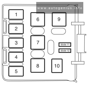
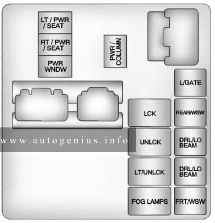
Engine compartment
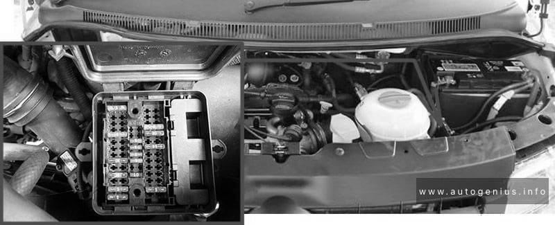
Fuse box location
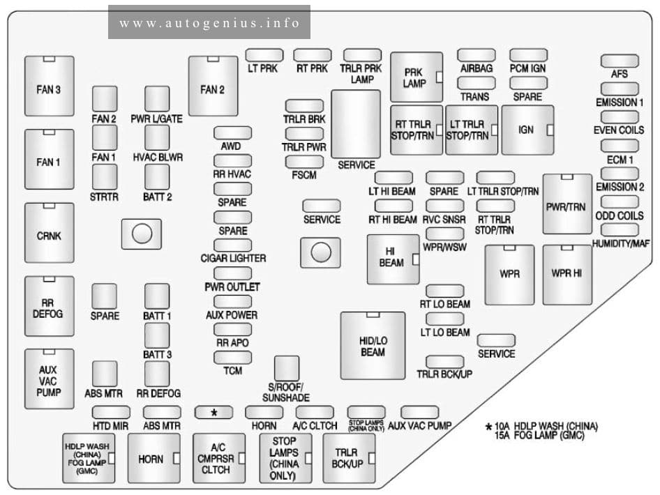
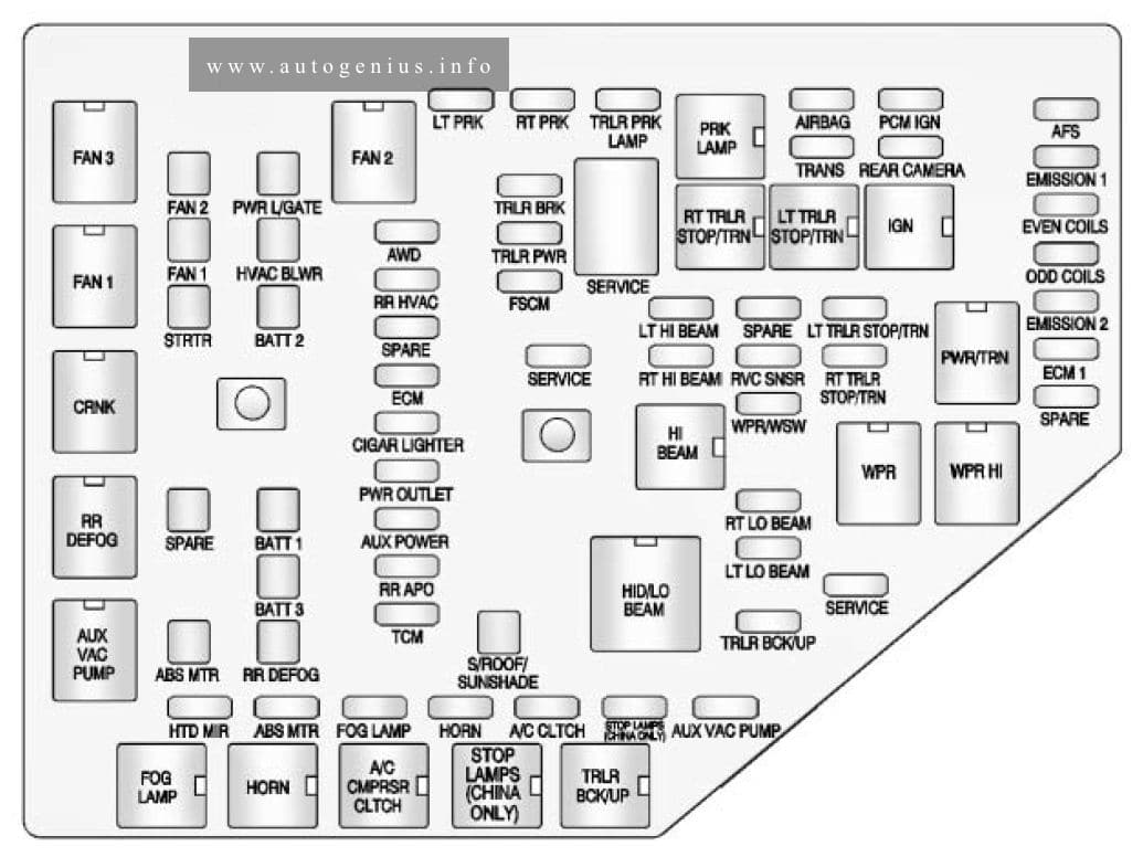
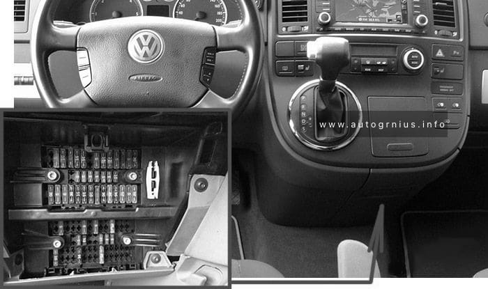
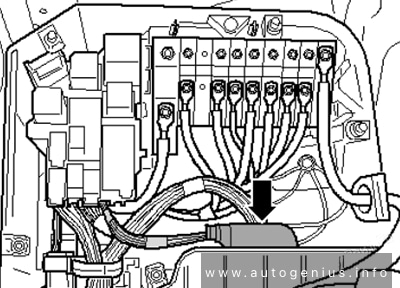
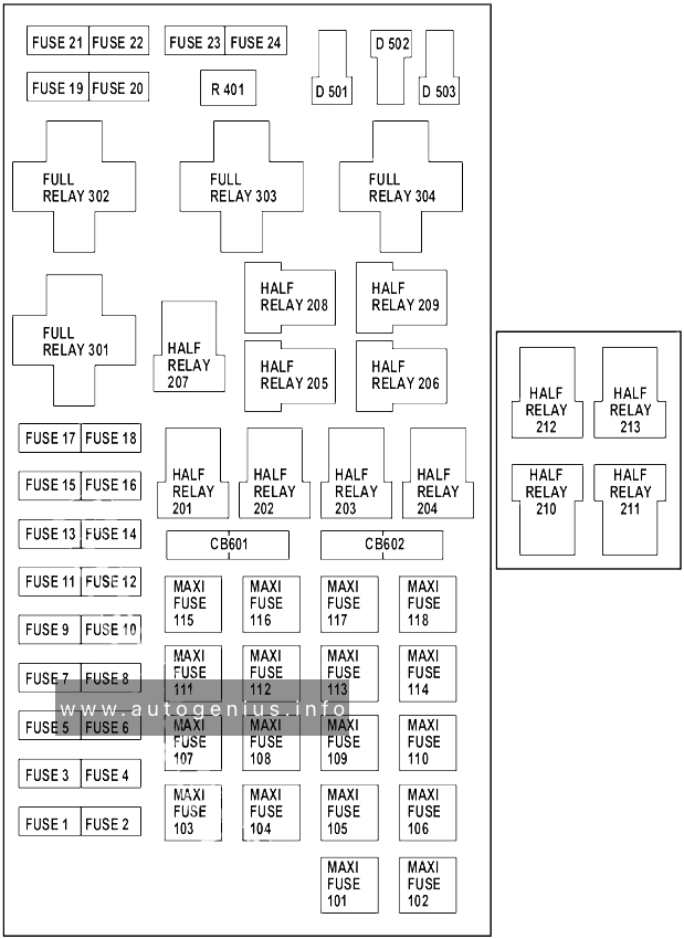
The underhood fuse block is located in the engine compartment, on the passenger side of the vehicle. Lift the cover for access to the fuse/relay block.
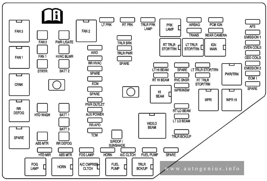
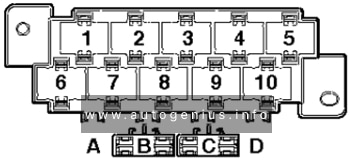
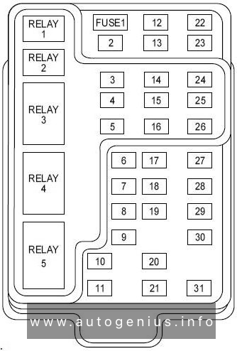
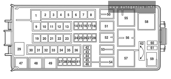
Fuse box diagram

Assignment of the fuses and relays in the engine compartment
| Fuses | Usage |
| A/C CLUTCH | Air Conditioning Clutch |
| ABS MTR | Antilock Braking System (ABS) Motor |
| AFS | Adaptive Forward Lighting System |
| AIRBAG | Airbag System |
| AUX POWER | Auxiliary Power |
| AUX VAC PUMP | Auxiliary Vacuum Pump |
| AWD | All-Wheel-Drive System |
| BATT 1 | Battery 1 |
| BATT 2 | Battery 2 |
| BATT 3 | Battery 3 |
| CIGAR LIGHTER | Cigar Lighter |
| ECM 1 | Engine Control Module 1 |
| ECM/ FPM IGN | Engine control module/Fuel pump control module ignition |
| EMISSION 1 | Emission 1 |
| EMISSION 2 | Emission 2 |
| EVEN COILS | Even Injector Coils |
| FAN 1 | Cooling Fan 1 |
| FAN 2 | Cooling Fan 1 |
| * | Headlamp Washer (China)/Fog Lamps (GMC) |
| FPM | Fuel pump power module |
| FSCM | Fuel System Control Module |
| FOG LAMP (GMC) | Fog Lamps (GMC) |
| HTD STR WHL | Heated steering wheel |
| HORN | Horn |
| HTD MIR | Heated Outside Rearview Mirror |
| HUMIDITY/MAF | Humidity Sensor/ MAF Sensor |
| HVAC BLWR | Heating, Ventilation and Air Conditioning Blower |
| LT HI BEAM | Left High-Beam Headlamp |
| LT LO BEAM | Left Low-Beam Headlamp |
| LT PRK | Left Parking Lamp |
| LT TRLR STOP/TRN | Trailer Left Stoplamp and Turn Signal |
| ODD COILS | Odd Injector Coils |
| PCM IGN | Powertrain Control Module Ignition |
| PWR L/GATE | Power Liftgate |
| PWR OUTLET | Power Outlet |
| RR APO | Rear Accessory Power Outlet |
| RR DEFOG | Rear Defogger |
| RR HVAC | Rear Climate Control System |
| RT HI BEAM | Right High-Beam Headlamp |
| RT LO BEAM | Right Low-Beam Headlamp |
| RT PRK | Right Parking Lamp |
| RT TRLR STOP/TRN | Trailer Right Stoplamp and Turn Signal |
| RVC SNSR | Regulated Voltage Control Sensor |
| S/ROOF/SUNSHADE | Sunroff |
| SERVICE | Service Repair |
| SPARE | Spare |
| Stop Lamps (China Only) | Stop Lamps (China Only) |
| STRTR | Starter |
| TCM | Transmission Control Module |
| TRANS | Transmission |
| TRLR BCK/UP | Trailer Back-up Lamps |
| TRLR BRK | Trailer Brake |
| TRLR PRK LAMP | Trailer Parking Lamps |
| TRLR PWR | Trailer Power |
| WPR/WSW | Windshield Wiper/Washer |
| Relays | Usage |
| A/C CMPRSR CLTCH | Air Conditioning Compressor Clutch |
| AUX VAC PUMP | Auxiliary Vacuum Pump |
| CRNK | Switched Power |
| FAN 1 | Cooling Fan 1 |
| FAN 2 | Cooling Fan 2 |
| FAN 3 | Cooling Fan 3 |
| HDLP WASH (CHINA) FOG LAMP (GMC) |
Headlamp Washer (China)/Fog Lamps (GMC) |
| HI BEAM | High-Beam Headlamps |
| HID/LO BEAM | High Intensity Discharge (HID) Low-Beam Headlamps |
| HORN | Horn |
| IGN | Ignition Main |
| LT TRLR STOP/TRN | Trailer Left Stoplamp and Turn Signal Lamp |
| PRK LAMP | Park Lamp |
| PWR/TRN | Powertrain |
| RR DEFOG | Rear Window Defogger |
| RT TRLR STOP/TRN | Trailer Right Stoplamp and Turn Signal Lamp |
| Stop Lamps (China Only) | Stop Lamps (China Only) |
| TRLR BCK/UP | Trailer Back-up Lamps |
| WPR | Windshield Wiper |
| WPR HI | Windshield Wiper High Speed |
Passenger compartment
Fuse box location
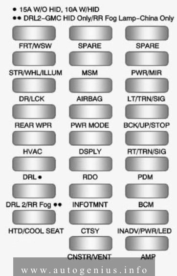
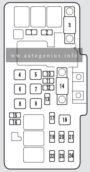
The instrument panel fuse block is located under the instrument panel on the passenger side of the vehicle. Pull down on the cover to access the fuse block.
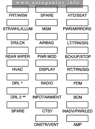
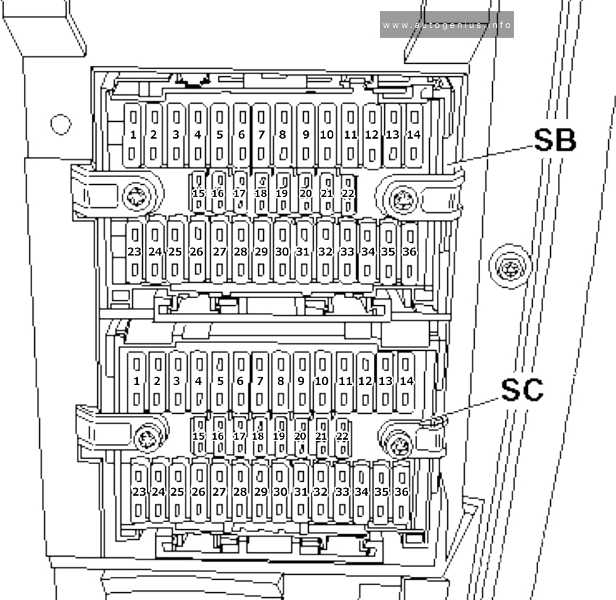
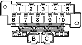
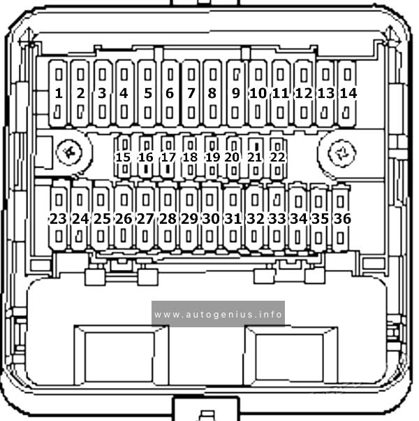
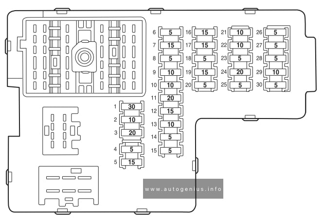
Fuse box diagram (fuse side)
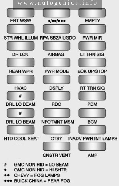
Assignment of the fuses and relays in the passenger compartment (fuse side)
| Fuses | Usage |
| # | GMC NON HID = Low Beam |
| * | GMC NON HID = High Shutter |
| ** | Chevy = Fog Lamps |
| *** | Buick China = Rear Fog Lamp |
| AIRBAG | Airbag |
| AMP | Amplifier |
| BCK UP/STOP | Back-up Lamp/Stoplamp |
| BCM | Body Control Module |
| CNSTR VENT | Canister Vent |
| CTSY | Courtesy |
| DRL LC | Door lock |
| DRL /LO BEAM | Daytime Running Lamps Relay/Low Beam Headlamps Relay |
| DSPLY | Display |
| FRT WSW | Front Windshield Washer |
| HTD/COOL SEAT | Heated/Cooling Seats |
| HVAC | Heating, Ventilation and Air Conditioning |
| INADV PWR INT LAMPS | Inadvertent Power/Interior Light Pipe Lamps |
| INFOTMNT/MSM | Infotainment/ Memory Seat Module |
| LT TRN SIG | Driver Side Turn Signal |
| OBS DET /URS | Rear park assist/ Side blind zone alert/Forward collision alert/ Universal remote system |
| PDM | Power Mirrors, Liftgate Release |
| PWR MODE | Power Mode |
| PWR MIR | Power Mirrors |
| RDO | Radio |
| REAR WPR | Rear Wiper |
| RT TRN SIG | Passenger Side Turn Signal |
| STR WHL ILLUM | Steering Wheel Illumination |
| USB CHRG | USB Charging |
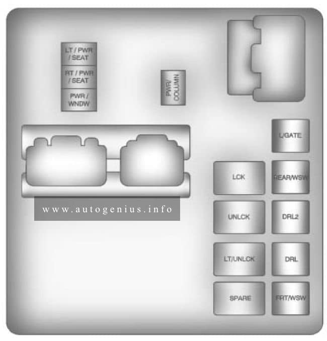
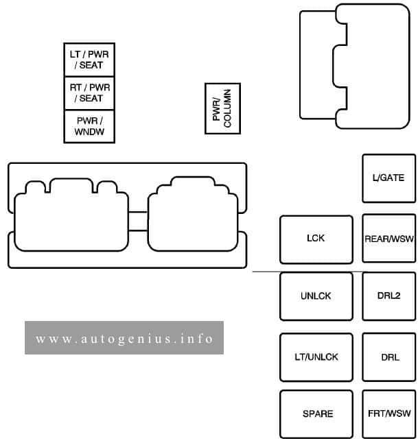
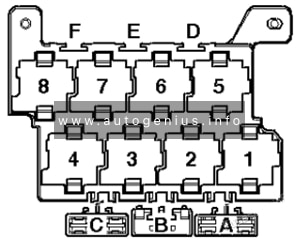
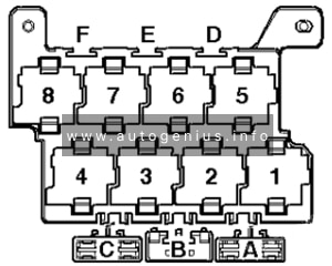
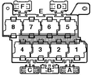
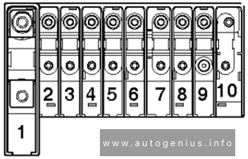
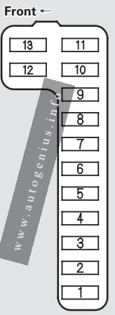
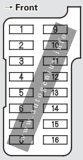
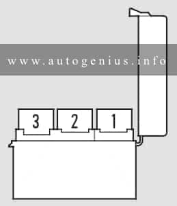
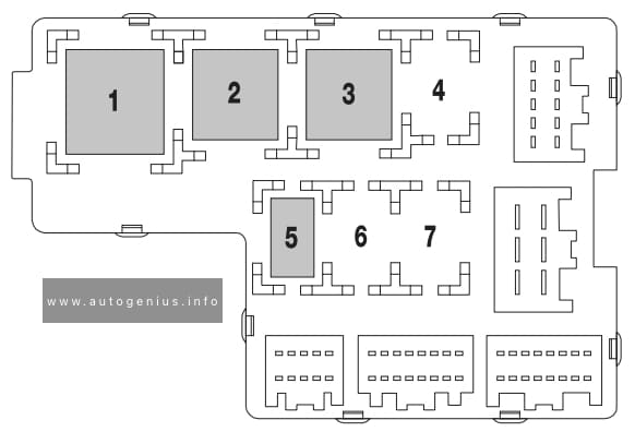
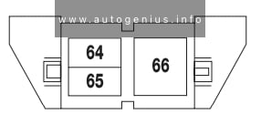
Fuse box diagram (relay side)
Assignment of the fuses and relays in the passenger compartment (relay side)
| Relays | Usage |
| LT/PWR/SEAT | Driver Side Power Seat Relay |
| RT/PWR/SEAT | Passenger Side Power Seat Relay |
| PWR/WNDW | Power Windows Relay |
| PWR/COLUMN | Power Steering Column Relay |
| L/GATE | Liftgate Relay |
| LCK | Power Lock Relay |
| REAR/WSW | Rear Window Washer Relay |
| UNLCK | Power Unlock Relay |
| DRL/LO BEAM | Daytime Running Lamps Relay/Low Beam Headlamps Relay |
| LT/UNLCK | Driver Side Unlock Relay |
| DRL/ LO BEAM | Daytime Running Lamps Relay (If Equipped) |
| REAR FOG LAMPS (CHINA) | Fog Lamps Relay (Chevy) |
| FRT/WSW | Front Windshield Washer Relay |
WARNING: Terminal and harness assignments for individual connectors will vary depending on vehicle equipment level, model, and market.