GAC GS3 Power (2021 – 2022) – fuse and relay box diagram
Year of production: 2021, 2022
The facelifted MG ZS, a subcompact crossover, has been available from 2021 to the present. This article features fuse box diagrams for the 2021, 2022, and 2023 models, provides information on the locations of the fuse panels inside the vehicle, and details the function of each fuse (fuse layout).
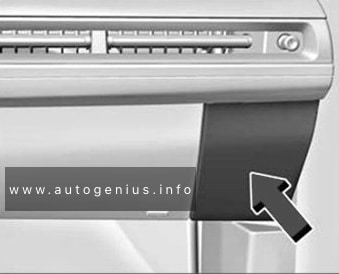
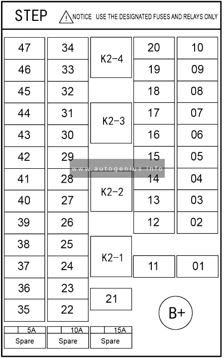
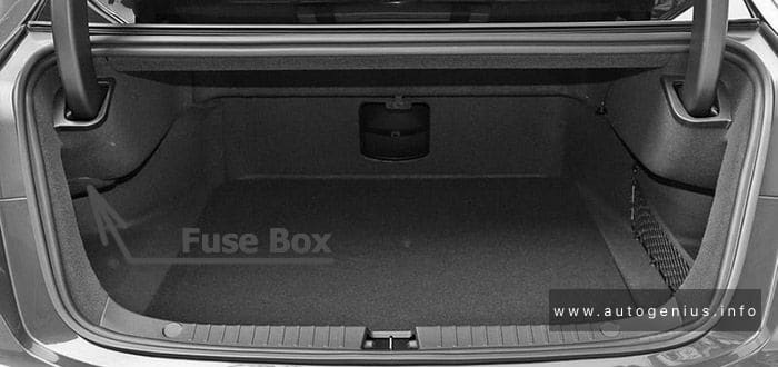
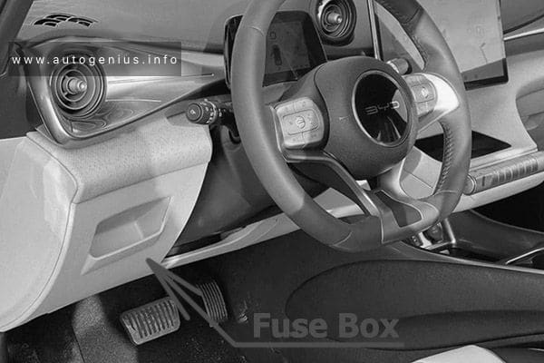
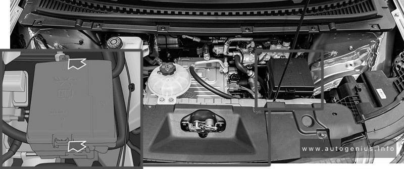
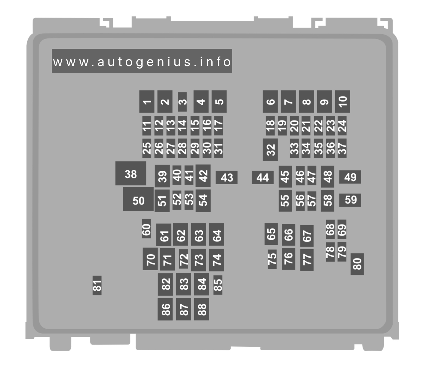
Passenger compartment fuse box
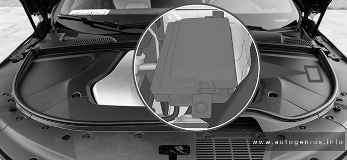
Fuse Box Location
Instrument panel PDU is installed inside the left instrument pane.
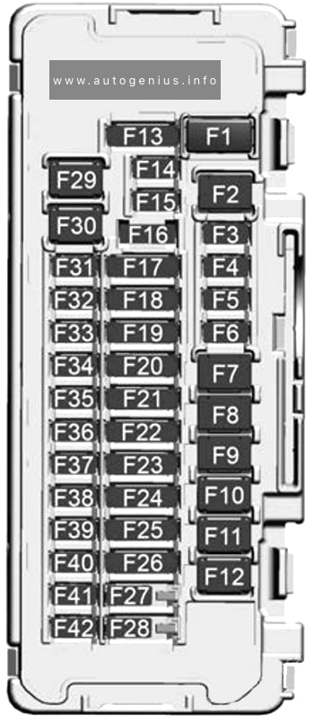
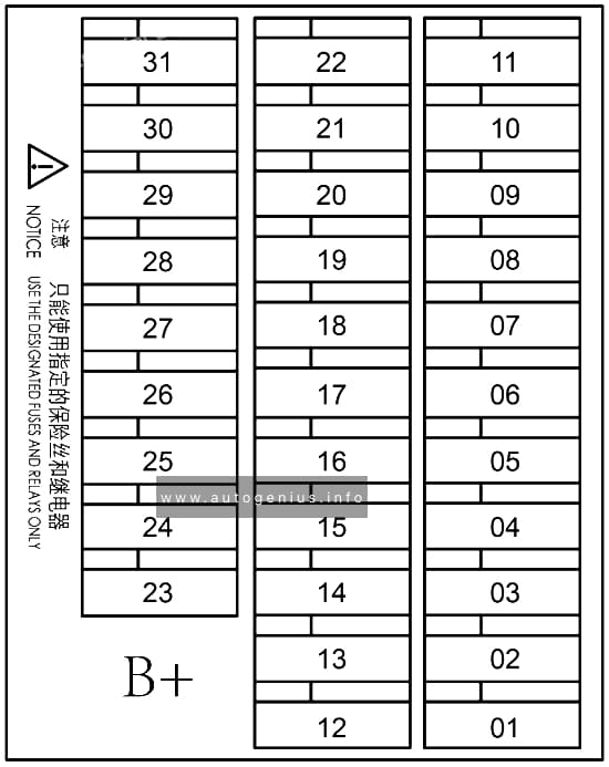
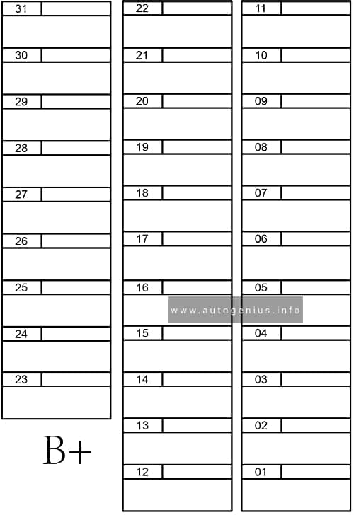
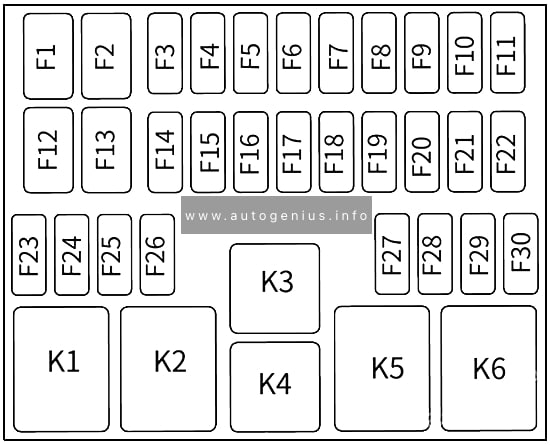
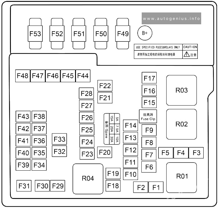
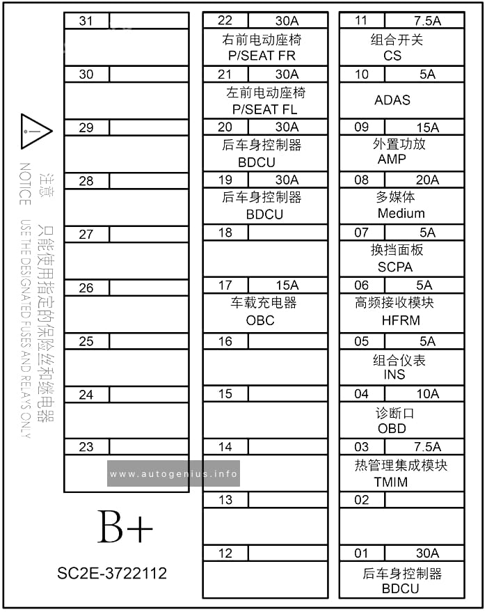
Fuse Box Diagram
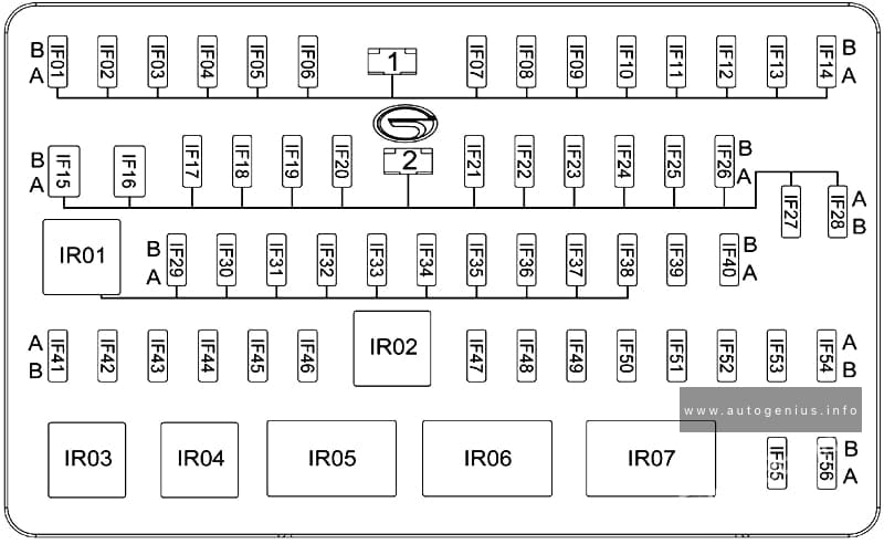
Assignment of the fuses in the dashboard
| № | Amps | Function / Component |
|---|---|---|
| IF01 | — | — |
| IF02 | 20A | Electric adjustment of left front seat |
| IF03 | 15A | Power sunroof ECU |
| IF04 | — | — |
| IF05 | — | — |
| IF06 | — | — |
| IF07 | 30A | BCM (front right window regulator) / BCM (rear right window regulator) |
| IF08 | 30A | BCM (front left window regulator) / BCM (rear left window regulator) |
| IF09 | — | — |
| IF10 | — | — |
| IF11 | 15A | BCM (windshield washer and rear wiper motor) |
| IF12 | 10A | Rearview mirror folding |
| IF13 | — | — |
| IF14 | 15A | IG2 relay |
| IF15 | — | — |
| IF16 | 30A | Instrument panel PDU |
| IF17 | 7.5A | OBD DLC |
| IF18 | 20A | BCM (main lamps) |
| IF19 | 7.5A | GWM / PEPS ECU |
| IF20 | — | — |
| IF21 | 10A | BCM (turn signal lamp) |
| IF22 | — | — |
| IF23 | 7.5A | Ignition switch / PEPS ECU |
| IF24 | 20A | BCM (main lamps) |
| IF25 | 7.5A | High-mounted stop lamp |
| IF26 | 20A | BCM (door lock) |
| IF27 | — | — |
| IF28 | SHUNT | Shorting link |
| IF29 | 10A | SRS ECU |
| IF30 | 7.5A | 1.5T GDI ECM / G-DCT TCU / 6AT TCU / 1.5TM ECM |
| IF31 | 7.5A | GWM / BCM / PEPS ECU |
| IF32 | — | — |
| IF33 | 7.5A | SAS / electric power steering control unit / 6AT GSM / G-DCT GSM |
| IF34 | 7.5A | ESPI / brake switch |
| IF35 | 7.5A | ACU / T-BOX ECU / instrument cluster |
| IF36 | 25A | Ignition switch |
| IF37 | 7.5A | Left front combination lamp (leveling motor) / right front combination lamp (leveling motor) / ALS switch / RPA ECU |
| IF38 | 7.5A | Power sunroof ECU / LDW ECU / Seat heater / HCP / HVAC control unit / negative ion generator |
| IF39 | 15A | 6AT TCU |
| IF40 | 20A | ACU |
| IF41 | 7.5A | BCM / PEPS ECU / G-DCT TCU |
| IF42 | 7.5A | USB 5V power supply |
| IF43 | — | — |
| IF44 | 7.5A | ACU / rearview mirror adjusting switch |
| IF45 | — | — |
| IF46 | 20A | Cigarette lighter |
| IF47 | — | — |
| IF48 | 7.5A | PEPS ECU |
| IF49 | 7.5A | Defogger relay / blower relay |
| IF50 | 7.5A | Ignition switch / PEPS ECU / BCM / G-DCT TCU / 1.5T GDI ECM / 1.5TM ECM |
| IF51 | 7.5A | T-BOX ECU |
| IF52 | 7.5A | HVAC control unit |
| IF53 | — | — |
| IF54 | 7.5A | LDW ECU / EPB switch / G-DCT GSM |
| IF55 | 15A | BCM |
| IF56 | 7.5A | HCP / instrument cluster / AV display |
| IR01 | — | IG1 relay |
| IR02 | — | IG2 relay |
| IR03 | — | — |
| IR04 | — | — |
| IR05 | — | ACC relay |
| IR06 | — | Rearview mirror folding relay |
| IR07 | — | Rearview mirror unfolding relay |
| IR06 | — | — |
| IR07 | — | IG2 relay |
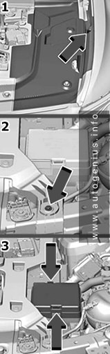
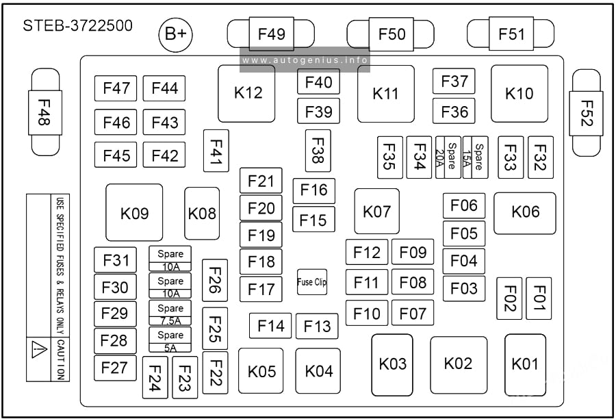
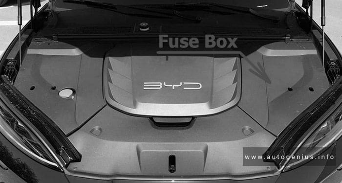
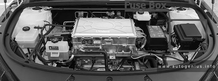
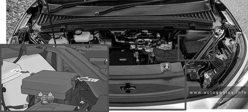
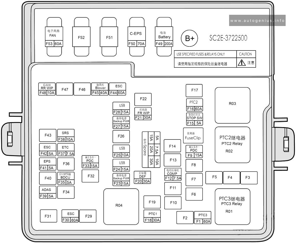
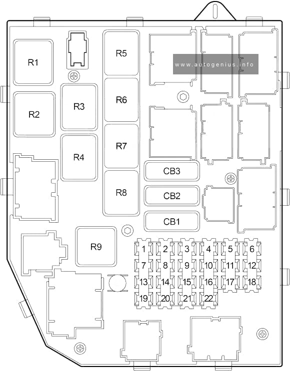
Engine Compartment Fuse Box
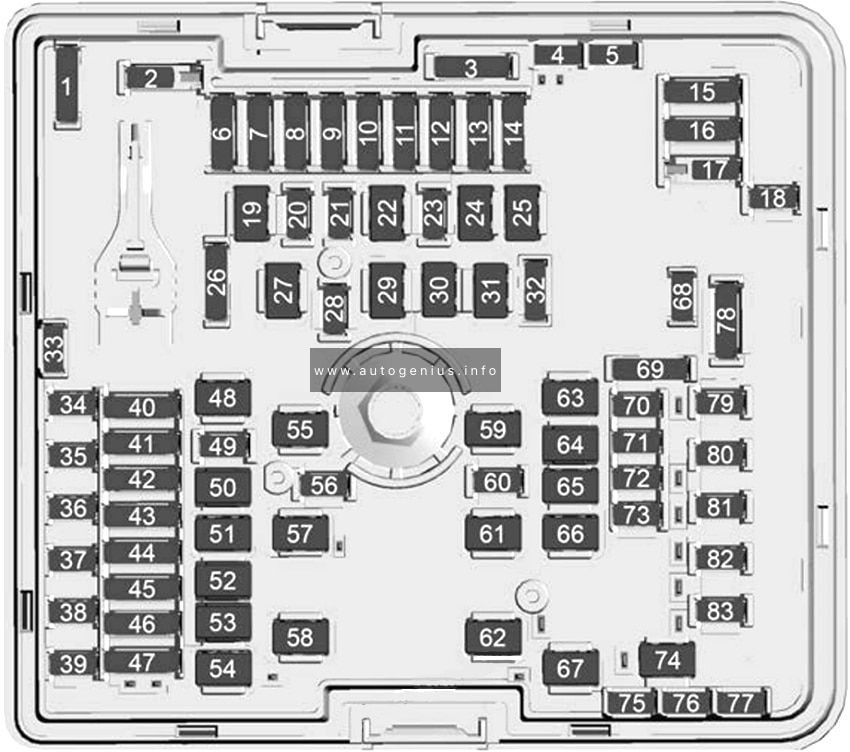
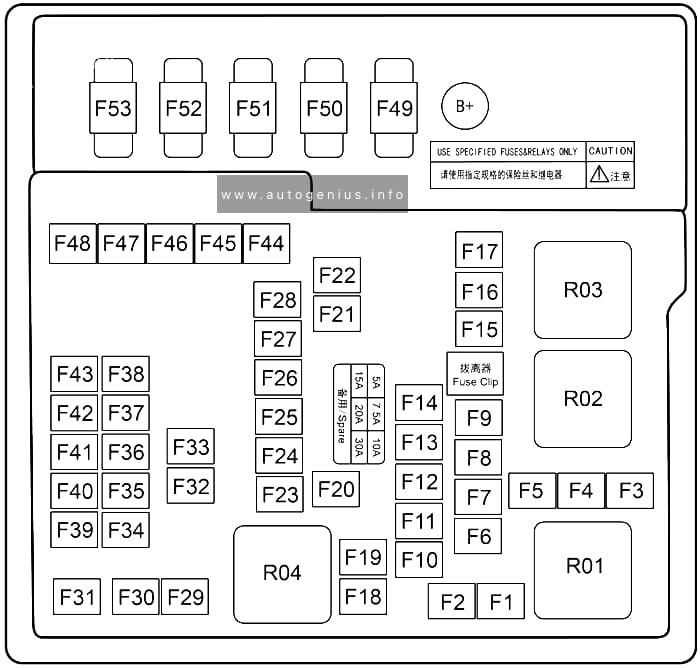
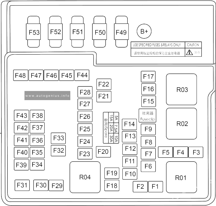
Fuse Box Diagram
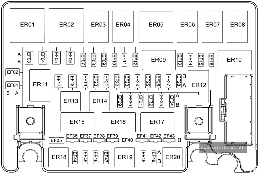
Assignment of the fuses in the engine compartment
| № | Amps | Function |
|---|---|---|
| EF01 | 50A | Low speed fan relay |
| EF02 | 50A | High speed fan relay 2 |
| EF03 | — | — |
| EF04 | — | — |
| EF05 | — | — |
| EF06 | 40A | ESPI |
| EF07 | 7.5A | A/C compressor |
| EF08 | 30A | IG1 relay |
| EF09 | — | — |
| EF10 | 20A | Seat heater |
| EF11 | — | — |
| EF12 | — | — |
| EF13 | 15A | Left front low beam |
| EF14 | 15A | Right front low beam |
| EF15 | 7.5A | 1.5TM ECM / 1.5T GDI ECM |
| EF16 | 7.5A | Rearview mirror heater |
| EF17 | 40A | G-DCT control unit |
| EF18 | 30A | ACC relay / ignition switch |
| EF19 | 7.5A | Brake switch / low beam relay / main relay / wiper speed control relay / wiper relay |
| EF20 | — | — |
| EF21 | — | — |
| EF22 | — | — |
| EF23 | 15A | Fuel pump |
| EF24 | 20A | Wiper |
| EF25 | 7.5A | G-DCT TCU / 1.5TGDI ECM / 1.5TM ECM |
| EF26 | 15A | Horn relay/horn |
| EF27 | 10A | G-DCT control unit |
| EF28 | 15A | High beam relay/left front high beam / right front high beam |
| EF29 | 10A | Electronic water pump |
| EF30 | 10A | VCT (exhaust) / VCT (intake) / canister solenoid valve / oil pump solenoid valve / clutch position sensor / CSV / relief valve / waste gate |
| EF31 | 10A | Downstream oxygen sensor / upstream oxygen sensor |
| EF32 | 15A | 1.5T GDI ECM / 1.5TM ECM |
| EF33 | 15A | Ignition coil 1 / ignition coil 2 / ignition coil 3 / ignition coil 4 |
| EF34 | 7.5A | Compressor relay / starter relay 1 / high speed fan relay 2 / starter relay 2 / low speed fan relay / fuel pump relay / high speed fan relay 1 |
| EF35 | 80A | EPS ECU |
| EF36 | — | — |
| EF37 | 40A | Blower |
| EF38 | 40A | ESPI |
| EF39 | 40A | Rear windshield defogger heater / rearview mirror heater |
| EF40 | 150A | Main fuse |
| EF41 | 30A | Starter relay 1 / ignition switch |
| EF42 | 50A | Instrument panel PDU |
| EF43 | 50A | Instrument panel PDU |
| EF44 | — | — |
| EF45 | — | — |
| EF46 | — | — |
| EF47 | — | — |
| EF48 | — | — |
| EF49 | — | — |
| ER01 | — | Low speed fan relay |
| ER02 | — | High speed fan relay 2 |
| ER03 | — | Fuel pump relay |
| ER04 | — | — |
| ER05 | — | High speed fan relay 1 |
| ER06 | — | Wiper speed control relay |
| ER07 | — | Wiper relay |
| ER08 | — | High beam relay |
| ER09 | — | Defogger relay |
| ER10 | — | Blower relay |
| ER11 | — | Low beam relay |
| ER12 | — | Main relay |
| ER13 | — | Compressor relay |
| ER14 | — | — |
| ER15 | — | Starter relay 1 |
| ER16 | — | Starter relay 2 |
| ER17 | — | — |
| ER18 | — | — |
| ER19 | — | Horn relay |
| ER20 | — | — |
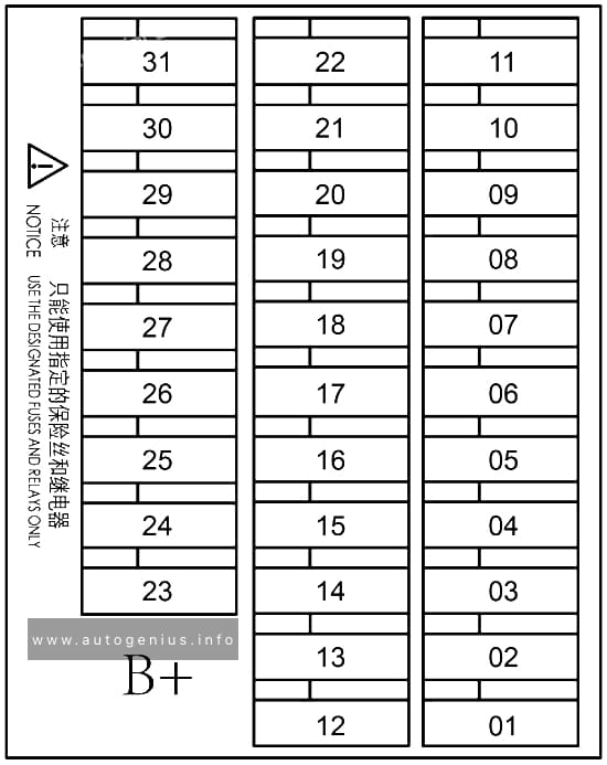
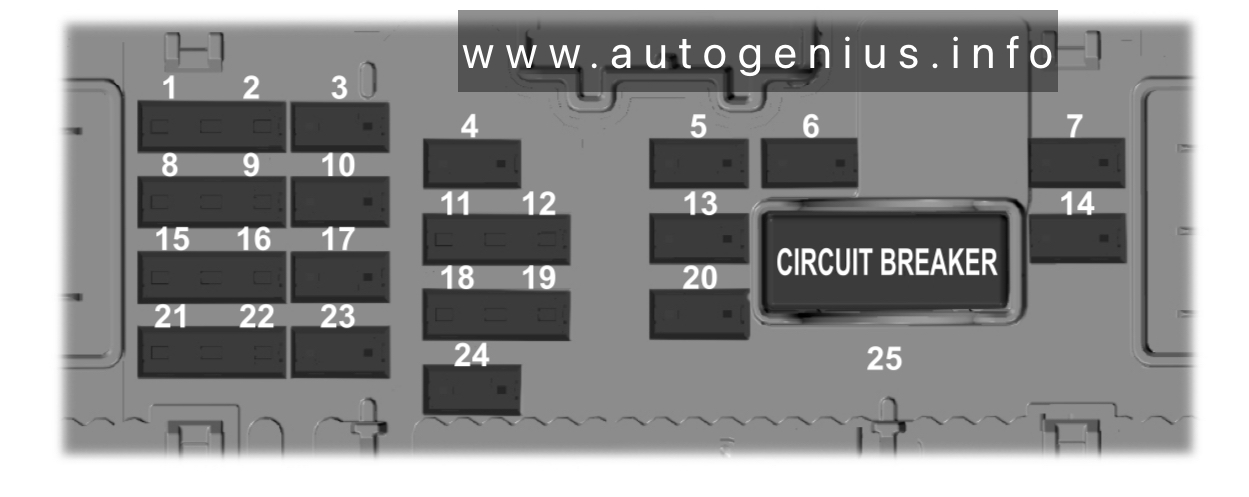
Fuses in battery PDU
Fuse Box Diagram
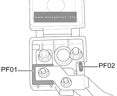
Assignment of the fuses in the engine compartment (battery PDU)
| № | Amps | Feature/component |
|---|---|---|
| PF01 | 300A | Starter / engine compartment PDU |
| PF02 | 7.5A | EBS |