Chevrolet Cruze (J400; 2016 – 2019) – fuse and relay box diagram
Year of production: 2016, 2017, 2018, 2019
This article covers the second-generation Chevrolet Cruze (J400), produced from 2016 to 2019. It features fuse box diagrams for the 2016, 2017, 2018, and 2019 models, provides information on the locations of the fuse panels within the vehicle, and details the function and layout of each fuse and relay.
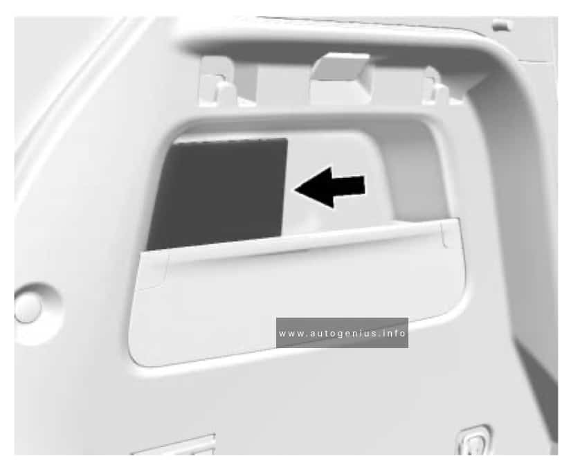
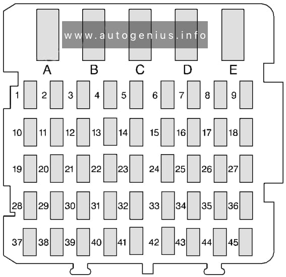
Instrument Panel Fuse Box
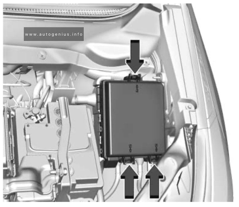
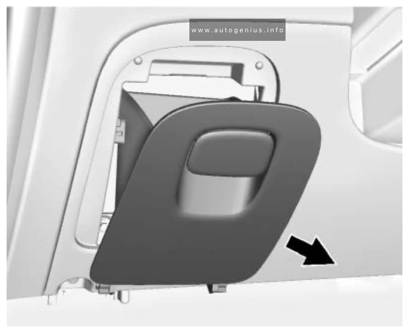
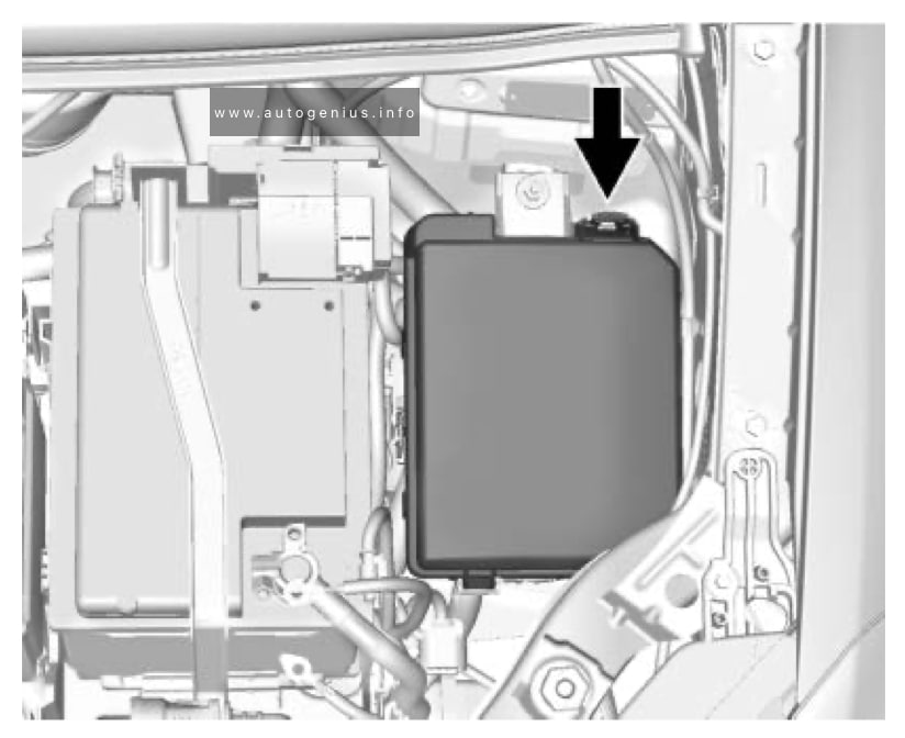
Fuse Box Location
It is located behind the cover in the central console under the HVAC controls.
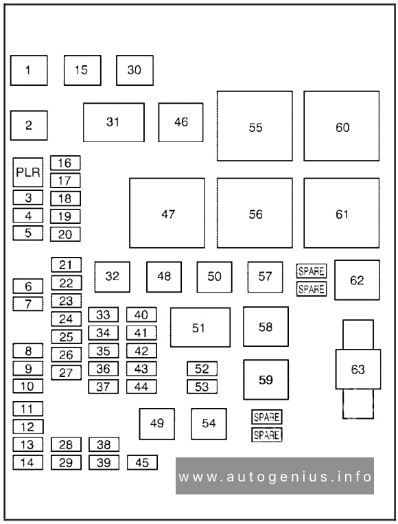
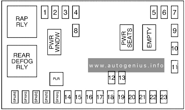
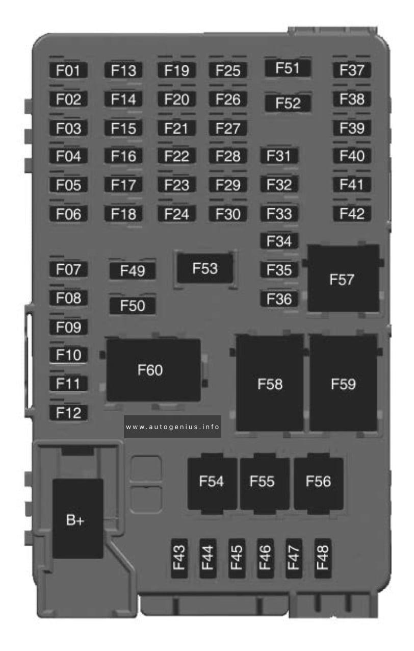
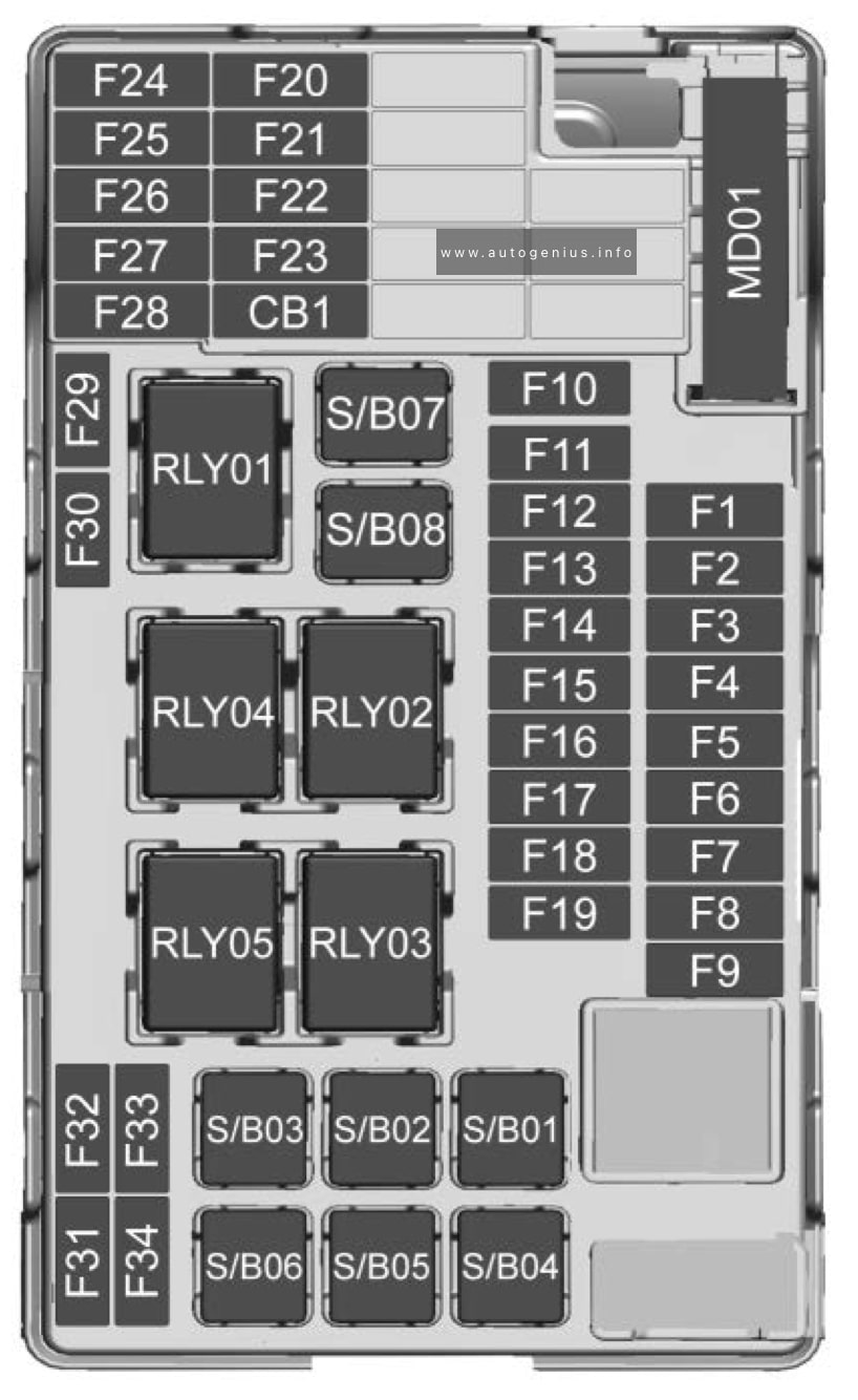
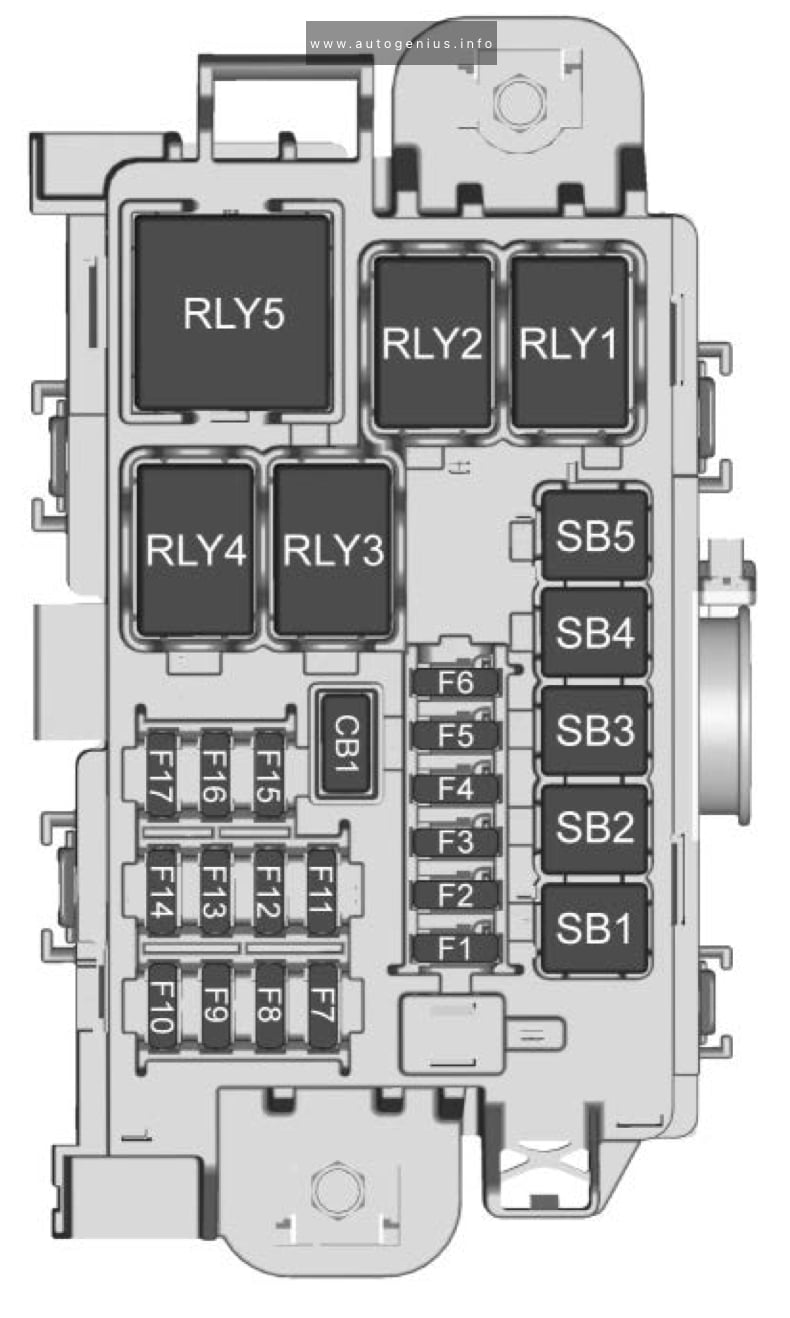
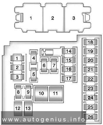
Fuse box diagram
Assignment of the fuses in the interior fuse box
| № | Description |
|---|---|
| F1 | 2016, 2018: Not Used. 2017: Right rear power window |
| F2 | Blower |
| F3 | Driver power seat |
| F4 | Front power outlet |
| F5 | 2016, 2018, 2019: Not Used. 2017: Right front power window |
| F6 | 2016, 2018, 2019: Front power windows 2017: Front left power window |
| F7 | ABS valves |
| F8 | Cyber gateway module (CGM) |
| F9 | Body control module 8 |
| F10 | 2016, 2018, 2019: Rear power windows. 2017: Left rear power window |
| F11 | Sunroof |
| F12 | Body control module 4 |
| F13 | Heated front seats |
| F14 | Exterior mirrors/Lane keep assist/ High-beam headlamp auto control |
| F15 | Body control module 1 |
| F16 | Body control module 7 |
| F17 | Body control module 6 |
| F18 | Body control module 3 |
| F19 | Data link connector |
| F20 | Airbag |
| F21 | A/C |
| F22 | Trunk release |
| F23 | Passive entry/ Passive start |
| F24 | 2016-2017: Right front child presence detection. 2018: Passenger sensing system. 2019: AOS (Automatic Occupant Sensing) system |
| F25 | Steering wheel switch illumination |
| F26 | Ignition switch |
| F27 | Body control module 2 |
| F28 | Amplifier |
| F29 | 2016-2017: Not Used. 2018-2019: USB charge |
| F30 | Shift lever illumination |
| F31 | Rear wiper |
| F32 | 2016-2018: Transmission control module (with Stop/ Start). 2019: Virtual key system |
| F33 | Mobile phone wireless charging/ DC AC converter |
| F34 | Parking assist/Side blind zone alert/ Infotainment/USB |
| F35 | OnStar |
| F36 | Display/Cluster |
| F37 | Radio |
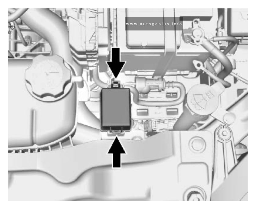
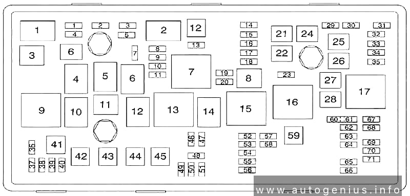
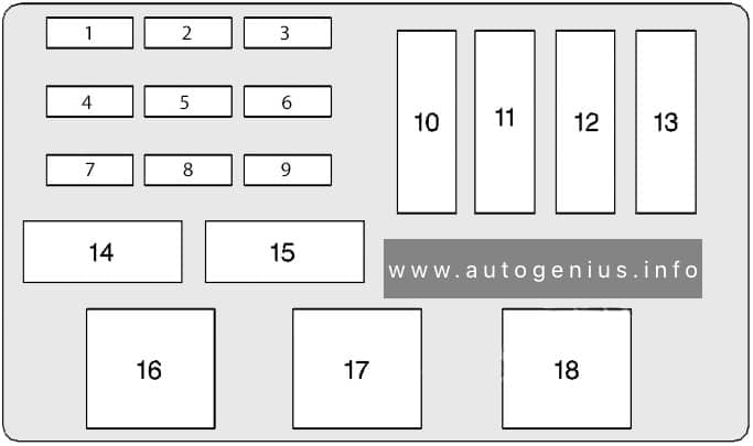
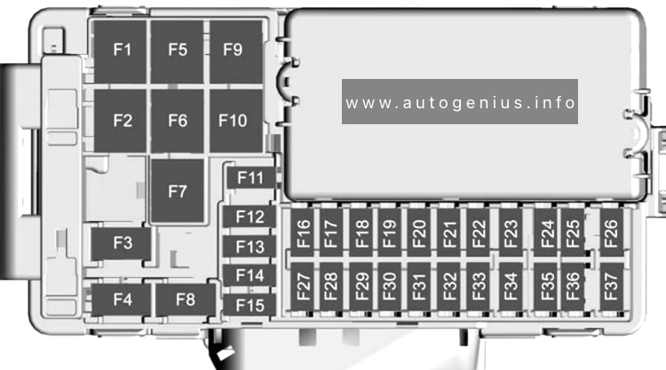
Engine Compartment Fuse Box
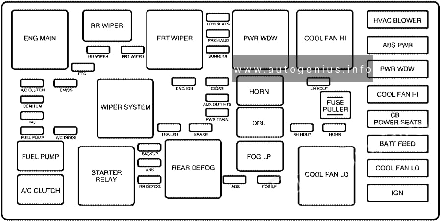
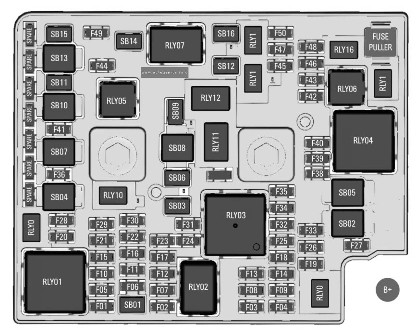
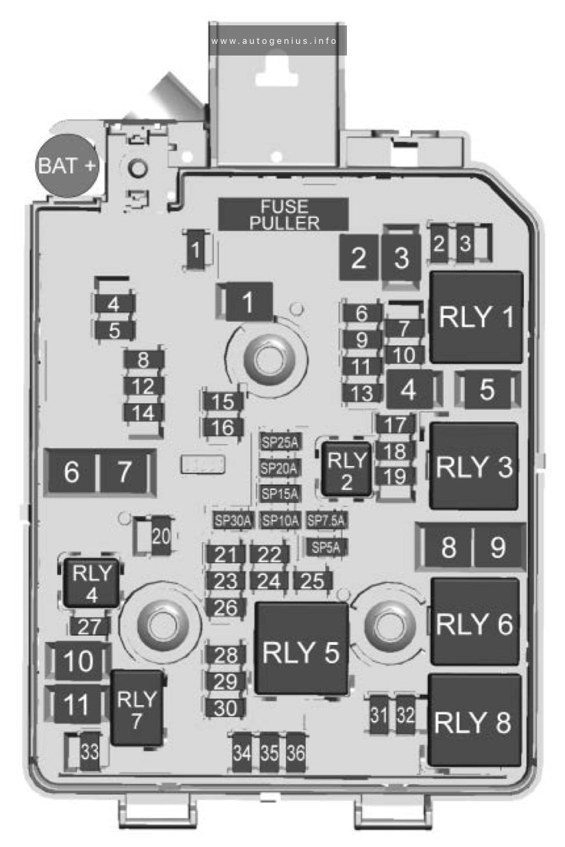
Fuse box diagram
Assignment of the fuses and relays in the engine compartment
| № | Description |
|---|---|
| F01 | Starter |
| F02 | Starter |
| F03 | O2 sensor |
| F04 | Engine control module |
| F05 | 2016-2018: Engine functions. 2019: Aero shutter/ Fuel flex |
| F06 | Transmission control module |
| F07 | Not Used |
| F08 | Engine control module |
| F09 | A/C |
| F10 | Canister vent |
| F11 | Heated seats |
| F12 | CGM module |
| F13 | 2016-2018: After boil pump/ Heated steering wheel. 2019: Aero shutter/Fuel flex |
| F14 | Diesel NOx/CVT8 transmission |
| F15 | O2 sensor |
| F16 | Fuel injection |
| F17 | Fuel injection |
| F18 | Diesel NOx |
| F19 | 2016-2018: Diesel NOx. 2019: Diesel NOx/Coolant motor |
| F20 | Not Used |
| F21 | 2016-2018: Electric parking brake. 2019: DC/AC converter |
| F22 | ABS system |
| F23 | Windshield washer/ Rear windows |
| F24 | Not Used |
| F25 | 2016-2018: Diesel fuel heating/ Secondary air induction. 2019: Diesel fuel heating |
| F26 | Transmission |
| F27 | Not Used |
| F28 | Not Used |
| F29 | Rear window defogger |
| F30 | Mirror defogger |
| F31 | Not Used |
| F32 | Display LED/DC DC converter/FPPM/ Electrical heater/A/C module |
| F33 | Anti-theft warning horn |
| F34 | Horn |
| F35 | Trunk power outlet |
| F36 | Right high-beam headlamp |
| F37 | Left high-beam headlamp |
| F38 | Not Used |
| F39 | Front fog lamps |
| F40 | AIR solenoid |
| F41 | Switchable water pump/Water in fuel sensor |
| F42 | Manual headlamp leveling |
| F43 | Fuel pump |
| F44 | Interior rearview mirror/Rear vision camera/Trailer |
| F45 | Fleated steering wheel |
| F46 | Cluster |
| F47 | Steering column lock |
| F48 | Rear wiper |
| F49 | Not Used |
| F50 | Not Used |
| F51 | Not Used |
| F52 | Engine/Transmission control module |
| F53 | Not Used |
| F54 | Windshield wiper |
| F55 | 2016-2018: Diesel NOx. 2019: Not Used |
| F56 | 2016-2018: Aeroshutter. 2019: Not Used |
| F57 | Not Used |
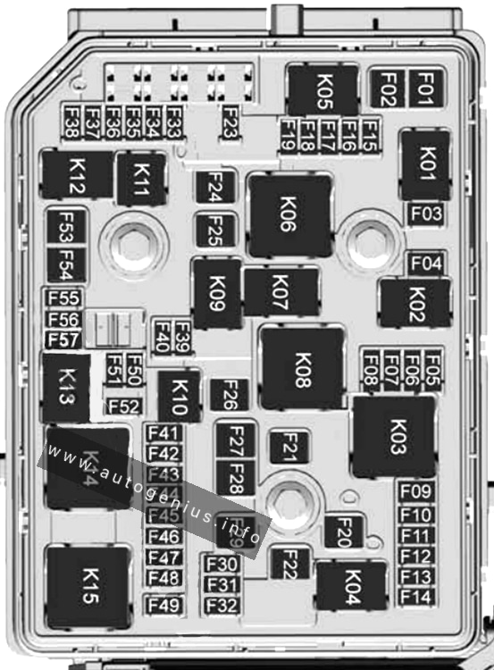
| Relays | |
| K01 | Starter |
| K02 | A/C control |
| K03 | Engine functions |
| K04 | 2016-2017: CVT8 transmission. 2018-2019: Not Used |
| K05 | Starter |
| K06 | Diesel fuel heating/ Secondary air induction |
| K07 | Right low-beam headlamp/Right daytime running lamp |
| K08 | Transmission |
| K09 | Diesel NOx |
| K10 | Fuel pump |
| K11 | — |
| K12 | High-beam headlamps |
| K13 | Left daytime running lamp/Left low-beam headlamp |
| K14 | Run/Crank |
| K15 | Mirror defogger/Rear window defogger/ Anti-theft warning sensor |
| K16 | Horn/Dual horn |
| K17 | Diesel NOx |
| K18 | Front fog lamps |
| K19 | After boil pump/ Heated steering wheel |
| K20 | Anti-theft warning horn |
| K21 | Rear window washer |
| K22 | Front window washer |
| K23 | Rear window wiper |
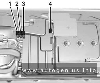
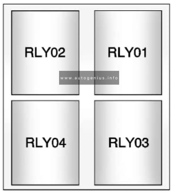
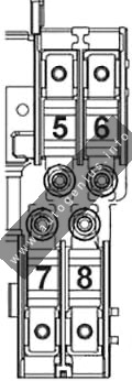
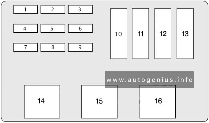
Assignment of the fuses and relays in the engine compartment (box no. 2)
| № | Description |
|---|---|
| 1 | 2018: Transmission control module (AT only). 2019: Engine control module |
| 2 | Fuel pump |
| 3 | 2018: Engine control module. 2019: Transmission control module |
| 4 | Power supply |
WARNING: Terminal and harness assignments for individual connectors will vary depending on vehicle equipment level, model, and market.